

Owners Manual
Page 14
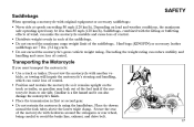
... the passenger to hold onto you or make movements that make the motorcycle hard to handle. Do not allow components to contact the road surface when leaning the motorcycle in handling, acceleration and braking caused by the additional weight of control. SAFETY Safe Riding Practices S Ground clearance is unaware of safe riding procedures may distract you or the seat strap...
... the passenger to hold onto you or make movements that make the motorcycle hard to handle. Do not allow components to contact the road surface when leaning the motorcycle in handling, acceleration and braking caused by the additional weight of control. SAFETY Safe Riding Practices S Ground clearance is unaware of safe riding procedures may distract you or the seat strap...
Owners Manual
Page 19
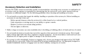
... motorcycle: S Use a truck or trailer. Secure the rear of the fuel tank if the motorcycle leans to avoid the brake line, exhaust, and drive belt. 17 S Position and restrain the motorcycle so it can also damage the motorcycle's finish. Exceeding the weight rating can cause loss of the saddlebags. Saddlebags, combined with original equipment or accessory saddlebags: S Never ride at speeds exceeding 80...
... motorcycle: S Use a truck or trailer. Secure the rear of the fuel tank if the motorcycle leans to avoid the brake line, exhaust, and drive belt. 17 S Position and restrain the motorcycle so it can also damage the motorcycle's finish. Exceeding the weight rating can cause loss of the saddlebags. Saddlebags, combined with original equipment or accessory saddlebags: S Never ride at speeds exceeding 80...
Owners Manual
Page 21
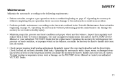
... luggage rack, choose one designed and approved by VICTORY specifically for proper installation and use. S If you from your ability to the electrical system. S Bulky or large accessories can reduce stability, causing loss of control. 19 An electrical failure could result and cause hazardous loss of engine power or lights or damage to operate controls. - Never install higher wattage light bulbs than...
... luggage rack, choose one designed and approved by VICTORY specifically for proper installation and use. S If you from your ability to the electrical system. S Bulky or large accessories can reduce stability, causing loss of control. 19 An electrical failure could result and cause hazardous loss of engine power or lights or damage to operate controls. - Never install higher wattage light bulbs than...
Owners Manual
Page 23
... repair steering or suspension system wear or damage, see the VICTORY Service Manual or your authorized VICTORY Dealer. 21 Regularly inspect the rear shock absorber and the front forks. Operating the motorcycle without completing the pre-operation check can make the motorcycle hard to handle and cause loss of control. S Check proper steering head bearing adjustment. S Maintain proper tire pressure and tread condition and...
... repair steering or suspension system wear or damage, see the VICTORY Service Manual or your authorized VICTORY Dealer. 21 Regularly inspect the rear shock absorber and the front forks. Operating the motorcycle without completing the pre-operation check can make the motorcycle hard to handle and cause loss of control. S Check proper steering head bearing adjustment. S Maintain proper tire pressure and tread condition and...

Owners Manual
Page 33
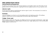
Front Fork Front Turn Signal Headlamp Speedometer Air Filter Spark Plug (2) Ignition Switch Left Side Cover Battery (under side cover) Taillight Rear Turn Signal Rear Axle Adjuster (1 each side) Rear Brake Caliper Passenger's Foot Rest Evaporative Canister - Components 1. 2. 3. 4. 5. 6. 7. 8. 9. 10. 11. 12. 13. 14. 15. 16. 17. 18. 19. 20. 21. 22. California Models Oil Filter Oil Drain Plug (on bottom of crankcase) Sidestand Operator's Foot Rest Gear Shift Lever Oil Cooler Front Brake Caliper 4 3 COMPONENT IDENTIFICATION 5 6 7 8 2 1 9 10 22 11 21 20 19 18 17 16 15 14 13 12 31
Front Fork Front Turn Signal Headlamp Speedometer Air Filter Spark Plug (2) Ignition Switch Left Side Cover Battery (under side cover) Taillight Rear Turn Signal Rear Axle Adjuster (1 each side) Rear Brake Caliper Passenger's Foot Rest Evaporative Canister - Components 1. 2. 3. 4. 5. 6. 7. 8. 9. 10. 11. 12. 13. 14. 15. 16. 17. 18. 19. 20. 21. 22. California Models Oil Filter Oil Drain Plug (on bottom of crankcase) Sidestand Operator's Foot Rest Gear Shift Lever Oil Cooler Front Brake Caliper 4 3 COMPONENT IDENTIFICATION 5 6 7 8 2 1 9 10 22 11 21 20 19 18 17 16 15 14 13 12 31

Owners Manual
Page 37
... 2. Ignition Switch The ignition switch energizes the ignition, the lighting system, and all electrical circuits are inactive and the ignition key can start the engine. Turn the ignition switch to the RUN position (see page 42) you can be removed. On 3. You must push the ignition key into the switch while selecting the Park position. 35 P (Park) Before starting the engine, read the instructions for starting the engine beginning on page 64. Ignition Key INSTRUMENTS, FEATURES AND CONTROLS The ignition key...
... 2. Ignition Switch The ignition switch energizes the ignition, the lighting system, and all electrical circuits are inactive and the ignition key can start the engine. Turn the ignition switch to the RUN position (see page 42) you can be removed. On 3. You must push the ignition key into the switch while selecting the Park position. 35 P (Park) Before starting the engine, read the instructions for starting the engine beginning on page 64. Ignition Key INSTRUMENTS, FEATURES AND CONTROLS The ignition key...

Owners Manual
Page 44
The engine should not start and run, press the lower portion of the turn the engine off under either normal or emergency conditions. 2 1 4 3 1. 2. 3. 4. Engine Stop/Run Switch Emergency Flasher Switch Starter Button Throttle Control Grip Emergency Flasher Switch (2) The emergency flasher switch activates and cancels the emergency flashers. To complete the circuits, allowing the engine to start or run switch (RUN position). Use the engine stop/run switch completes or interrupts the ignition, starter, and fuel pump circuits. When...
The engine should not start and run, press the lower portion of the turn the engine off under either normal or emergency conditions. 2 1 4 3 1. 2. 3. 4. Engine Stop/Run Switch Emergency Flasher Switch Starter Button Throttle Control Grip Emergency Flasher Switch (2) The emergency flasher switch activates and cancels the emergency flashers. To complete the circuits, allowing the engine to start or run switch (RUN position). Use the engine stop/run switch completes or interrupts the ignition, starter, and fuel pump circuits. When...

Owners Manual
Page 47
To close the key slot cover. For fueling procedure, see Fueling and Fill Height, page 63. 1 45 Turn key counterclockwise while maintaining pressure on the cap and insert key. Turn clockwise while pushing down on the cap. Remove key and close the fuel cap, turn key clockwise and press down lightly to release latch and open the cap. Lift the key slot cover (1) on the cap. Fuel Cap INSTRUMENTS, FEATURES AND CONTROLS The fuel cap must be opened and closed with the ignition key.
To close the key slot cover. For fueling procedure, see Fueling and Fill Height, page 63. 1 45 Turn key counterclockwise while maintaining pressure on the cap and insert key. Turn clockwise while pushing down on the cap. Remove key and close the fuel cap, turn key clockwise and press down lightly to release latch and open the cap. Lift the key slot cover (1) on the cap. Fuel Cap INSTRUMENTS, FEATURES AND CONTROLS The fuel cap must be opened and closed with the ignition key.
Owners Manual
Page 50
... oil pressure indicator should increase. 48 If the transmission is in the ON position, the taillight and the license plate light should remain illuminated. PRE-OPERATION CHECK Check Electrical Equipment To perform a pre-operation check on . Taillight / Brake Light With the ignition switch in neutral, the neutral indicator should illuminate. taillight brightness should illuminate until the engine is on the electrical equipment, set the ignition switch...
... oil pressure indicator should increase. 48 If the transmission is in the ON position, the taillight and the license plate light should remain illuminated. PRE-OPERATION CHECK Check Electrical Equipment To perform a pre-operation check on . Taillight / Brake Light With the ignition switch in neutral, the neutral indicator should illuminate. taillight brightness should illuminate until the engine is on the electrical equipment, set the ignition switch...

Owners Manual
Page 68
... right. HEEL / TOE SHIFT PEDAL: (Bottom Photo) Shift to a lower gear, depress the front pedal with your heel. The motorcycle is between first and second gear. With the ignition switch set to shift gears. To shift to a higher gear by lifting the front of the motorcycle. Forced shifting (shifting without the clutch disengaged) may damage the engine, transmission and drive train, causing loss of control of the pedal with...
... right. HEEL / TOE SHIFT PEDAL: (Bottom Photo) Shift to a lower gear, depress the front pedal with your heel. The motorcycle is between first and second gear. With the ignition switch set to shift gears. To shift to a higher gear by lifting the front of the motorcycle. Forced shifting (shifting without the clutch disengaged) may damage the engine, transmission and drive train, causing loss of control of the pedal with...

Owners Manual
Page 73
... stop the engine, set the engine stop either in motion and the engine stops on its own, guide the motorcycle to the OFF position, and remove the ignition key. In either case, you may damage the engine and the transmission or cause the rear wheel to a complete stop /run switch to the STOP position, turn the ignition switch to a safe location off the road and away...
... stop the engine, set the engine stop either in motion and the engine stops on its own, guide the motorcycle to the OFF position, and remove the ignition key. In either case, you may damage the engine and the transmission or cause the rear wheel to a complete stop /run switch to the STOP position, turn the ignition switch to a safe location off the road and away...

Owners Manual
Page 87
... sprocket nut retainer screws and the retainer. 4. Remove the drive sprocket cover. Apply the rear brake and tighten the drive sprocket nut. Notice On some models you cannot align the mounting holes, tighten the sprocket nut slightly and install the nut ...Service Manual or an authorized VICTORY dealer). Torque: 125 ft-lbs (170 Nm) 9. Install the nut retainer and the retainer screws. If you may have to remove portions of the exhaust system to access all of LOCTITE Thread Locker #262 or equivalent to the output shaft threads. 8. Check rear wheel alignment (page 89) and drive belt...
... sprocket nut retainer screws and the retainer. 4. Remove the drive sprocket cover. Apply the rear brake and tighten the drive sprocket nut. Notice On some models you cannot align the mounting holes, tighten the sprocket nut slightly and install the nut ...Service Manual or an authorized VICTORY dealer). Torque: 125 ft-lbs (170 Nm) 9. Install the nut retainer and the retainer screws. If you may have to remove portions of the exhaust system to access all of LOCTITE Thread Locker #262 or equivalent to the output shaft threads. 8. Check rear wheel alignment (page 89) and drive belt...

Owners Manual
Page 92
MAINTENANCE Rear Wheel Alignment (cont.) NOTE: Turn the axle adjusters about 1/16 of the swingarm and turn at a time and monitor wheel alignment as outlined after each adjustment. Recheck rear wheel alignment as you proceed. 5. Readjust if necessary, until the marks on both axle washers are in the same position in the back of a turn the axle adjuster bolt IN (clockwise) to draw the axle back...
MAINTENANCE Rear Wheel Alignment (cont.) NOTE: Turn the axle adjusters about 1/16 of the swingarm and turn at a time and monitor wheel alignment as outlined after each adjustment. Recheck rear wheel alignment as you proceed. 5. Readjust if necessary, until the marks on both axle washers are in the same position in the back of a turn the axle adjuster bolt IN (clockwise) to draw the axle back...

Owners Manual
Page 97
... Nm) 2. With the transmission in the operator's seat and slowly bounce the rear suspension a few times. If there is movement at the front of the motorcycle until the rear wheel is still present, inspect the swing arm pivot bushings (see the VICTORY Service Manual or an authorized VICTORY dealer). 6. Rear Suspension MAINTENANCE Inspect Swing Arm and Rear Axle 1. Remove the swing arm pivot covers and tighten the swingarm...
... Nm) 2. With the transmission in the operator's seat and slowly bounce the rear suspension a few times. If there is movement at the front of the motorcycle until the rear wheel is still present, inspect the swing arm pivot bushings (see the VICTORY Service Manual or an authorized VICTORY dealer). 6. Rear Suspension MAINTENANCE Inspect Swing Arm and Rear Axle 1. Remove the swing arm pivot covers and tighten the swingarm...

Owners Manual
Page 99
... Steering WARNING MAINTENANCE Care should be taken to -side. Grasp the front tire and attempt to move the front wheel front-to-back. Severe personal injury or death may occur if the motorcycle tips or falls. NOTE: If there is no front-to -back movement at the front axle, inspect the wheel bearings and front axle (see the VICTORY Service Manual...
... Steering WARNING MAINTENANCE Care should be taken to -side. Grasp the front tire and attempt to move the front wheel front-to-back. Severe personal injury or death may occur if the motorcycle tips or falls. NOTE: If there is no front-to -back movement at the front axle, inspect the wheel bearings and front axle (see the VICTORY Service Manual...

Owners Manual
Page 102
... problem persists contact your VICTORY dealer. B 100 Loosen the fast idle cable adjuster jam nut (B). 4. Start the engine and let it idle with transmission in . It should move smoothly from full right to the point of cable resistance. If adjustment is 1/8-1/4 inch (3-6 mm). 5. If engine RPM increases when bars are turned, re-check throttle cable and fast idle cable adjustments, cable condition...
... problem persists contact your VICTORY dealer. B 100 Loosen the fast idle cable adjuster jam nut (B). 4. Start the engine and let it idle with transmission in . It should move smoothly from full right to the point of cable resistance. If adjustment is 1/8-1/4 inch (3-6 mm). 5. If engine RPM increases when bars are turned, re-check throttle cable and fast idle cable adjustments, cable condition...

Owners Manual
Page 140
... area to replace the oil filter at this time, but you must replace the oil filter when you poured in the spark plug holes. 5. Settled carbon deposits can cause engine damage. 2. Start and run switch set to RUN, and the transmission in service, settle on internal engine components during storage. Pour one tablespoon of the filler insert. 2. STORAGE Fuel Stabilizer 1. WARNING Wear face protection when using pressurized air. 3. Change the engine oil (see page...
... area to replace the oil filter at this time, but you must replace the oil filter when you poured in the spark plug holes. 5. Settled carbon deposits can cause engine damage. 2. Start and run switch set to RUN, and the transmission in service, settle on internal engine components during storage. Pour one tablespoon of the filler insert. 2. STORAGE Fuel Stabilizer 1. WARNING Wear face protection when using pressurized air. 3. Change the engine oil (see page...
Owners Manual
Page 145
... your owner's manual. VICTORY recommends that includes as to conform at the time of initial retail purchases with applicable regulations of the United States Environmental Protection Agency or the California Air Resources Board for your failure to ensure the performance of all receipts covering maintenance on Emission Control System VICTORY Motorcycle Division, Polaris Sales Inc., (hereinafter VICTORY) warrants that each new 2004...
... your owner's manual. VICTORY recommends that includes as to conform at the time of initial retail purchases with applicable regulations of the United States Environmental Protection Agency or the California Air Resources Board for your failure to ensure the performance of all receipts covering maintenance on Emission Control System VICTORY Motorcycle Division, Polaris Sales Inc., (hereinafter VICTORY) warrants that each new 2004...

Owners Manual
Page 160
... 129 N Neutral Indicator ...38 Noise Emission Warranty ...141 Noise Regulation ...141 158 INDEX F I IDENTIFICATION NUMBERS ...156 Ignition Key ...35 Ignition Key Number ...34 Ignition Switch ...35 Indicator Lights ...38, 48 Initial Maintenance ...75 Instrument Cluster ...36 INSTRUMENTS, FEATURES AND CONTROLS ...35-46 INTRODUCTION ...5 O Odometer ...36 Oil ...81-83 Oil Change ...81-82 Oil Filter ...81-82 Oil Filter Change ...81-82 Oil Level ...50, 82-83 Oil Specifications ...151 OPERATION ...60-73 Out of Fuel, Procedures ...63 Fuel Stabilizer ...138 Fuel System...
... 129 N Neutral Indicator ...38 Noise Emission Warranty ...141 Noise Regulation ...141 158 INDEX F I IDENTIFICATION NUMBERS ...156 Ignition Key ...35 Ignition Key Number ...34 Ignition Switch ...35 Indicator Lights ...38, 48 Initial Maintenance ...75 Instrument Cluster ...36 INSTRUMENTS, FEATURES AND CONTROLS ...35-46 INTRODUCTION ...5 O Odometer ...36 Oil ...81-83 Oil Change ...81-82 Oil Filter ...81-82 Oil Filter Change ...81-82 Oil Level ...50, 82-83 Oil Specifications ...151 OPERATION ...60-73 Out of Fuel, Procedures ...63 Fuel Stabilizer ...138 Fuel System...

Owners Manual
Page 161
... ...120 Service Manual, Part Number ...151 Shift Points ...68 Shifting Gears ...66-68 Shock Absorber ...92-93 Side Covers ...46 Sidestand ...46, 59, 126-127 Sidestand Lubrication ...127 Sidestand Pad ...126 Spark Plugs ...118-119 SPECIFICATIONS ...151-155 Speedometer ...36 Starter Button ...43 Starting the Engine ...64-65 Steering ...57, 96-97 Stop/Run Switch ...42, 49 Stopping the Engine ...71 STORAGE ...137-140 Suspension, Front ...57, 96-97 Suspension, Rear...
... ...120 Service Manual, Part Number ...151 Shift Points ...68 Shifting Gears ...66-68 Shock Absorber ...92-93 Side Covers ...46 Sidestand ...46, 59, 126-127 Sidestand Lubrication ...127 Sidestand Pad ...126 Spark Plugs ...118-119 SPECIFICATIONS ...151-155 Speedometer ...36 Starter Button ...43 Starting the Engine ...64-65 Steering ...57, 96-97 Stop/Run Switch ...42, 49 Stopping the Engine ...71 STORAGE ...137-140 Suspension, Front ...57, 96-97 Suspension, Rear...