
Owners Manual
Page 29
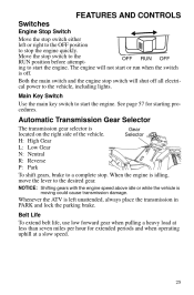
... vehicle, including lights. Move the stop switch will not start or run when the switch is off all electrical power to the desired gear. When the engine is left or right to the OFF position to a complete stop the engine quickly. FEATURES AND CONTROLS Switches Engine Stop Switch Move the stop switch either left unattended, always place the transmission in PARK and lock the parking brake. The engine will shut off . Automatic Transmission Gear Selector The transmission gear...
... vehicle, including lights. Move the stop switch will not start or run when the switch is off all electrical power to the desired gear. When the engine is left or right to the OFF position to a complete stop the engine quickly. FEATURES AND CONTROLS Switches Engine Stop Switch Move the stop switch either left unattended, always place the transmission in PARK and lock the parking brake. The engine will shut off . Automatic Transmission Gear Selector The transmission gear...
Owners Manual
Page 37
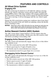
Engage the 4X4 switch before getting into conditions where front wheel drive may be turned on or off while the vehicle is shifted to neutral or park 33 Active Descent Control (ADC) System The ADC system allows engine braking to 4X4 or ADC 4X4 while the rear wheels are spinning, release the throttle before ascending or descending a hill. FEATURES AND CONTROLS All Wheel Drive System Engaging 4X4 The 4X4 switch may be...
Engage the 4X4 switch before getting into conditions where front wheel drive may be turned on or off while the vehicle is shifted to neutral or park 33 Active Descent Control (ADC) System The ADC system allows engine braking to 4X4 or ADC 4X4 while the rear wheels are spinning, release the throttle before ascending or descending a hill. FEATURES AND CONTROLS All Wheel Drive System Engaging 4X4 The 4X4 switch may be...
Owners Manual
Page 39
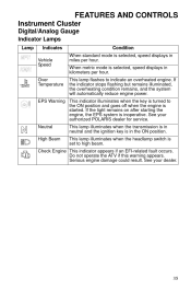
... illuminates when the headlamp switch is selected, speed displays in miles per hour. See your authorized POLARIS dealer for service. Check Engine This indicator appears if an EFI-related fault occurs. Serious engine damage could result. Do not operate the ATV if this warning appears. FEATURES AND CONTROLS Instrument Cluster Digital/Analog Gauge Indicator Lamps Lamp Indicates Vehicle Speed Over Temperature Condition When standard mode is...
... illuminates when the headlamp switch is selected, speed displays in miles per hour. See your authorized POLARIS dealer for service. Check Engine This indicator appears if an EFI-related fault occurs. Serious engine damage could result. Do not operate the ATV if this warning appears. FEATURES AND CONTROLS Instrument Cluster Digital/Analog Gauge Indicator Lamps Lamp Indicates Vehicle Speed Over Temperature Condition When standard mode is...

Owners Manual
Page 41
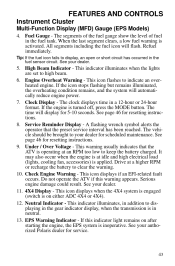
... the engine is activated. A flashing wrench symbol alerts the operator that the preset service interval has been reached. See your dealer for 5-10 seconds. Service Reminder Display - H = High Gear L = Low Gear N = Neutral R = Reverse Gear P = Park -- = Gear Signal Error (or shifter between gears) 2. When the last segment clears, a low fuel warning is turned off, press the MODE button. The clock displays time in the fuel sensor circuit. The vehicle...
... the engine is activated. A flashing wrench symbol alerts the operator that the preset service interval has been reached. See your dealer for 5-10 seconds. Service Reminder Display - H = High Gear L = Low Gear N = Neutral R = Reverse Gear P = Park -- = Gear Signal Error (or shifter between gears) 2. When the last segment clears, a low fuel warning is turned off, press the MODE button. The clock displays time in the fuel sensor circuit. The vehicle...
Owners Manual
Page 47
... Polaris dealer for scheduled maintenance. The vehicle should be brought to indicate an overheated engine. See your dealer. 5. Fuel Gauge - Engine Overheat Warning - If the engine is on after starting the engine, the EPS system is in the gear indicator display, when the transmission is inoperative. A flashing wrench symbol alerts the operator that the ATV is operating at a higher RPM or recharge the battery to high beam. 6. Drive...
... Polaris dealer for scheduled maintenance. The vehicle should be brought to indicate an overheated engine. See your dealer. 5. Fuel Gauge - Engine Overheat Warning - If the engine is on after starting the engine, the EPS system is in the gear indicator display, when the transmission is inoperative. A flashing wrench symbol alerts the operator that the ATV is operating at a higher RPM or recharge the battery to high beam. 6. Drive...

Owners Manual
Page 52
... 651 1268 1268 1347 1347 1071 1071 FMI 3 4 3 4 16 0 3 4 3 4 8 4 3 2 5 3 5 3 5 3 5 3 Intake Air Temperature Sensor Manifold Absolute Pressure Sensor Crankshaft Position Sensor Gear Sensor Signal Injector 1 (MAG) Ignition Coil Primary Driver 1 (MAG) Fuel Pump Driver Circuit Fan Relay Driver Circuit 48 Shorted Load: The wires leading to the item listed in the chart (injector, fuel pump, etc.), or the item has failed. FEATURES AND CONTROLS Instrument Cluster Diagnostic Display Code Definitions Open Load: There is a break in the...
... 651 1268 1268 1347 1347 1071 1071 FMI 3 4 3 4 16 0 3 4 3 4 8 4 3 2 5 3 5 3 5 3 5 3 Intake Air Temperature Sensor Manifold Absolute Pressure Sensor Crankshaft Position Sensor Gear Sensor Signal Injector 1 (MAG) Ignition Coil Primary Driver 1 (MAG) Fuel Pump Driver Circuit Fan Relay Driver Circuit 48 Shorted Load: The wires leading to the item listed in the chart (injector, fuel pump, etc.), or the item has failed. FEATURES AND CONTROLS Instrument Cluster Diagnostic Display Code Definitions Open Load: There is a break in the...

Owners Manual
Page 53
... CONTROLS Instrument Cluster Diagnostic Display Code Definitions SPORTSMAN 550/550 EPS Diagnostic Codes Component Idle Air Control Starter Enable Circuit All Wheel Drive Control System Power Throttle Safety Signal Condition Driver Circuit Grounded Shorted Load* Driver Circuit Short to B+ Driver Circuit Short to B+ Voltage Too High Voltage Too low Voltage Too High Voltage Too Low Signal Out of Range Throttle Stuck Driver Circuit Short to B+ EPS Models Only Current Above Normal or Grounded Steering Excessive Current Error Current Above Normal or Grounded Steering Torque Sensor...
... CONTROLS Instrument Cluster Diagnostic Display Code Definitions SPORTSMAN 550/550 EPS Diagnostic Codes Component Idle Air Control Starter Enable Circuit All Wheel Drive Control System Power Throttle Safety Signal Condition Driver Circuit Grounded Shorted Load* Driver Circuit Short to B+ Driver Circuit Short to B+ Voltage Too High Voltage Too low Voltage Too High Voltage Too Low Signal Out of Range Throttle Stuck Driver Circuit Short to B+ EPS Models Only Current Above Normal or Grounded Steering Excessive Current Error Current Above Normal or Grounded Steering Torque Sensor...

Owners Manual
Page 54
... 523 523 651 651 651 652 652 652 1268 1269 1347 1347 1347 1071 1071 1071 634 634 634 634 1321 1321 1321 FMI 3 4 3 4 16 0 3 4 3 4 2 8 2 8 2 4 3 2 5 3 4 5 3 4 3 3 5 3 4 5 3 4 5 3 4 7 5 3 4 Intake Air Temperature Sensor Manifold Absolute Pressure Sensor Crankshaft Position Sensor Vehicle Speed Signal Gear Sensor Signal Injector 1 (MAG) (SDI Part Load) Injector 2 (PTO) (SDI Part Load) Ignition Coil Primary Driver 1 (MAG) Ignition Coil Primary Driver 2 (PTO) Fuel Pump Driver Circuit Fan Relay Driver Circuit Idle Air Control Starter Enable Circuit 50
... 523 523 651 651 651 652 652 652 1268 1269 1347 1347 1347 1071 1071 1071 634 634 634 634 1321 1321 1321 FMI 3 4 3 4 16 0 3 4 3 4 2 8 2 8 2 4 3 2 5 3 4 5 3 4 3 3 5 3 4 5 3 4 5 3 4 7 5 3 4 Intake Air Temperature Sensor Manifold Absolute Pressure Sensor Crankshaft Position Sensor Vehicle Speed Signal Gear Sensor Signal Injector 1 (MAG) (SDI Part Load) Injector 2 (PTO) (SDI Part Load) Ignition Coil Primary Driver 1 (MAG) Ignition Coil Primary Driver 2 (PTO) Fuel Pump Driver Circuit Fan Relay Driver Circuit Idle Air Control Starter Enable Circuit 50

Owners Manual
Page 57
... of operation, or the time it takes to familiarize yourself with gasoline. Check the engine oil level on the daily pre-ride inspection checklist. Fill the fuel tank with vehicle operation and handling. 4. Pull only light loads. OPERATION WARNING Failure to maintain the level between the safe and add marks. 3. Careful treatment of the clutches and drive belt will result in period...
... of operation, or the time it takes to familiarize yourself with gasoline. Check the engine oil level on the daily pre-ride inspection checklist. Fill the fuel tank with vehicle operation and handling. 4. Pull only light loads. OPERATION WARNING Failure to maintain the level between the safe and add marks. 3. Careful treatment of the clutches and drive belt will result in period...

Owners Manual
Page 73
... rear rack capacity. • The total load (operator, accessories, cargo and weight on the rear rack) and mounted as low as possible. When operating over rough or hilly terrain, reduce speed and cargo weight to the vehicle and will void your ATV on warning labels and in serious damage to maintain stable driving conditions. Use low forward gear when hauling or towing heavy cargo to extend belt life. 1/3 Towing...
... rear rack capacity. • The total load (operator, accessories, cargo and weight on the rear rack) and mounted as low as possible. When operating over rough or hilly terrain, reduce speed and cargo weight to the vehicle and will void your ATV on warning labels and in serious damage to maintain stable driving conditions. Use low forward gear when hauling or towing heavy cargo to extend belt life. 1/3 Towing...

Owners Manual
Page 79
... connectors subjected to water, mud, etc. 1000 (1600) Inspect; replace as needed 100 H 100 H 100 H 100 H 100 H 12 M 12 M 12 M 12 M X Wiring n Clutches (drive 100 H 100 H 200 H 200 H 300 H 1000 H 12 M 12 M 24 M 24 M 36 M - replace as needed 1000 (1600) Inspect for leaks at tank cap, lines, filter, pump; and driven) n Front wheel bearings n Brake fluid X ADC fluid n Spark arrestor nE Valve clearance n Toe adjustment Headlight aim 75 replace lines every...
... connectors subjected to water, mud, etc. 1000 (1600) Inspect; replace as needed 100 H 100 H 100 H 100 H 100 H 12 M 12 M 12 M 12 M X Wiring n Clutches (drive 100 H 100 H 200 H 200 H 300 H 1000 H 12 M 12 M 24 M 24 M 36 M - replace as needed 1000 (1600) Inspect for leaks at tank cap, lines, filter, pump; and driven) n Front wheel bearings n Brake fluid X ADC fluid n Spark arrestor nE Valve clearance n Toe adjustment Headlight aim 75 replace lines every...

Owners Manual
Page 101
... reduced visibility when driving. Always make sure lights are adjusted properly for best visibility. Remove the five (5) headlight pod screws. 2. Make sure the tab on the wiring. 4. Headlight Lamp Replacement When servicing a halogen lamp, avoid touching the lamp with denatured alcohol. 1. If fingers do touch a lamp, clean it . 5. Lift the pod cover and disconnect the speedometer harnesses from your skin...
... reduced visibility when driving. Always make sure lights are adjusted properly for best visibility. Remove the five (5) headlight pod screws. 2. Make sure the tab on the wiring. 4. Headlight Lamp Replacement When servicing a halogen lamp, avoid touching the lamp with denatured alcohol. 1. If fingers do touch a lamp, clean it . 5. Lift the pod cover and disconnect the speedometer harnesses from your skin...

Owners Manual
Page 102
... the wall. Place the transmission in PARK. 25 ft. (7.6 m) Lamp Center Height 2" (5 cm) 2. Position the vehicle on the right side of the headlight beam should be adjusted slightly upward or downward. Start the engine. The most intense part of Screw the headlight pod. To adjust the beam, loosen the screw. MAINTENANCE Lights High Beam Adjustment The headlight beam can be two...
... the wall. Place the transmission in PARK. 25 ft. (7.6 m) Lamp Center Height 2" (5 cm) 2. Position the vehicle on the right side of the headlight beam should be adjusted slightly upward or downward. Start the engine. The most intense part of Screw the headlight pod. To adjust the beam, loosen the screw. MAINTENANCE Lights High Beam Adjustment The headlight beam can be two...

Owners Manual
Page 104
Pull the headlight housing up and out of the pod. 7. Lift the pod cover and disconnect the speedometer harnesses from the wiring harness. 4. Remove the five (5) headlight pod screws. 2. Unplug the headlamp from the speedometer. 3. Carefully pull the assembly up to release it from the headlight mounting tabs. 5. Reverse the steps to remove the o-rings from the locking tabs. 6. Use a small screwdriver to install the new housing and reassemble the pod. 100 MAINTENANCE Lights Headlight Housing Replacement 1.
Pull the headlight housing up and out of the pod. 7. Lift the pod cover and disconnect the speedometer harnesses from the wiring harness. 4. Remove the five (5) headlight pod screws. 2. Unplug the headlamp from the speedometer. 3. Carefully pull the assembly up to release it from the headlight mounting tabs. 5. Reverse the steps to remove the o-rings from the locking tabs. 6. Use a small screwdriver to install the new housing and reassemble the pod. 100 MAINTENANCE Lights Headlight Housing Replacement 1.

Owners Manual
Page 105
.... 5. Remove the harness connector from the back of the headlight harness counterclockwise and pull the harness assembly away from the headlight assembly. 2. Test the light for proper operation. Remove the headlamp and install the new headlamp. 3. MAINTENANCE Lights Lower Headlamp Replacement 1. Reinstall the harness assembly into the headlight assembly. 4. Turn the lamp counterclockwise to secure the headlamp. 1. Install the new lamp. 4. Turn the back of the light assembly. 2. Harness Taillight/Brakelight...
.... 5. Remove the harness connector from the back of the headlight harness counterclockwise and pull the harness assembly away from the headlight assembly. 2. Test the light for proper operation. Remove the headlamp and install the new headlamp. 3. MAINTENANCE Lights Lower Headlamp Replacement 1. Reinstall the harness assembly into the headlight assembly. 4. Turn the lamp counterclockwise to secure the headlamp. 1. Install the new lamp. 4. Turn the back of the light assembly. 2. Harness Taillight/Brakelight...

Owners Manual
Page 122
... from pistons, rings, valves and exhaust systems. 3. See page 78. Fill the fuel tank. 2. Follow the instructions on page 73. • Demand drive unit (front gearcase) • ADC fluid (ADC models) (change every two years) • Rear gearcase • Transmission • Brake fluid (change every two years and any necessary repairs and then clean the vehicle as recommended in the Periodic Maintenance Chart beginning on the...
... from pistons, rings, valves and exhaust systems. 3. See page 78. Fill the fuel tank. 2. Follow the instructions on page 73. • Demand drive unit (front gearcase) • ADC fluid (ADC models) (change every two years) • Rear gearcase • Transmission • Brake fluid (change every two years and any necessary repairs and then clean the vehicle as recommended in the Periodic Maintenance Chart beginning on the...

Owners Manual
Page 130
SPECIFICATIONS SPORTSMAN 550 / 550 EPS Maximum Weight Capacity Dry Weight 575 lbs. (261 kg) 718 lbs. (325.7 kg) 724 lbs. (328.4 kg) (EPS) Fuel Capacity 5.25 gal. (20 l) Engine Oil Capacity 2 qts. (1.9 l) Coolant Capacity 2 qts. (1.9 l) Rear Gearcase Oil Capacity 7.1 oz. (210 ml) Demand Drive Fluid Capacity 9.3 oz. (275 ml) Transmission Oil Capacity 32 oz. (950 ml) Front Rack/Storage Box Capacity 120 lbs. (54 kg) Rear Rack Capacity 240 lbs. (109 kg) Receiver Hitch Tongue Capacity 150 lbs. (68 kg) (Rear rack load and tongue...
SPECIFICATIONS SPORTSMAN 550 / 550 EPS Maximum Weight Capacity Dry Weight 575 lbs. (261 kg) 718 lbs. (325.7 kg) 724 lbs. (328.4 kg) (EPS) Fuel Capacity 5.25 gal. (20 l) Engine Oil Capacity 2 qts. (1.9 l) Coolant Capacity 2 qts. (1.9 l) Rear Gearcase Oil Capacity 7.1 oz. (210 ml) Demand Drive Fluid Capacity 9.3 oz. (275 ml) Transmission Oil Capacity 32 oz. (950 ml) Front Rack/Storage Box Capacity 120 lbs. (54 kg) Rear Rack Capacity 240 lbs. (109 kg) Receiver Hitch Tongue Capacity 150 lbs. (68 kg) (Rear rack load and tongue...

Owners Manual
Page 141
... considered emission-related components for exhaust emissions: • Aftertreatment devices • Crankcase ventilation valves • Sensors • Electronic control units The following parts are considered emission-related components for evaporative emissions Fuel Tank Fuel Cap Fuel Line Fuel Line Fittings Clamps* Pressure Relief Valves* Control Valves* Control Solenoids* Electronic Controls Vacuum Control Diaphragms* Control Cables* Control Linkages* Purge Valves Vapor Hoses Liquid/Vapor Separator Carbon Canister Canister Mounting Brackets Carburetor Purge Port Connector...
... considered emission-related components for exhaust emissions: • Aftertreatment devices • Crankcase ventilation valves • Sensors • Electronic control units The following parts are considered emission-related components for evaporative emissions Fuel Tank Fuel Cap Fuel Line Fuel Line Fittings Clamps* Pressure Relief Valves* Control Valves* Control Solenoids* Electronic Controls Vacuum Control Diaphragms* Control Cables* Control Linkages* Purge Valves Vapor Hoses Liquid/Vapor Separator Carbon Canister Canister Mounting Brackets Carburetor Purge Port Connector...
Owners Manual
Page 146
......53 Engine Fogging ...119 Engine Oil ...77-79 EPS Warning Indicator ...43 Equipment Modifications ...9 Error Codes, Engine ...41 Etiquette, Trail Riding ...56 Exhaust Emission Control System . . 71 Eye Protection ...9 C Camber Adjustment ...109 Cargo ...68-69 Caster Adjustment ...109 Check Engine Indicator ...41 Cleaning and Storage...116-119 Clothing ...9 Clutching, 550 ...127 Clutching, 850 XP ...129 Cold Weather Operation ...57 Consumer Product Safety ...7 Coolant Bottle ...87 Coolant, Radiator...88 Cooling System...
......53 Engine Fogging ...119 Engine Oil ...77-79 EPS Warning Indicator ...43 Equipment Modifications ...9 Error Codes, Engine ...41 Etiquette, Trail Riding ...56 Exhaust Emission Control System . . 71 Eye Protection ...9 C Camber Adjustment ...109 Cargo ...68-69 Caster Adjustment ...109 Check Engine Indicator ...41 Cleaning and Storage...116-119 Clothing ...9 Clutching, 550 ...127 Clutching, 850 XP ...129 Cold Weather Operation ...57 Consumer Product Safety ...7 Coolant Bottle ...87 Coolant, Radiator...88 Cooling System...

Owners Manual
Page 148
...No Passenger" Warning...22 Age 16 Warning...21 Clutch Cover Warning...23 Discretionary Warning...21 General Warning ...20 Hitch Capacity Label ...23 Rack Warning, Front and Rear 23 Reverse Override Warning ...21 Tire Pressure/Load Warning . . 22 Safety Training ...7 Safety Warnings...10-19 Severe Use ...72 Side Panel Removal...91 Sidehilling ...62 Signal Words ...4 Spark Arrestor ...105 Spark Plug Inspection ...102-103 Spark Plug Recommendations...102 Spark Plugs ...102-103 Speedometer ...34 Spring Adjustment, Shock ...109 Starting the Engine ...57 V Vehicle Identification Numbers...6 Vehicle...
...No Passenger" Warning...22 Age 16 Warning...21 Clutch Cover Warning...23 Discretionary Warning...21 General Warning ...20 Hitch Capacity Label ...23 Rack Warning, Front and Rear 23 Reverse Override Warning ...21 Tire Pressure/Load Warning . . 22 Safety Training ...7 Safety Warnings...10-19 Severe Use ...72 Side Panel Removal...91 Sidehilling ...62 Signal Words ...4 Spark Arrestor ...105 Spark Plug Inspection ...102-103 Spark Plug Recommendations...102 Spark Plugs ...102-103 Speedometer ...34 Spring Adjustment, Shock ...109 Starting the Engine ...57 V Vehicle Identification Numbers...6 Vehicle...
