
Owners Manual
Page 29
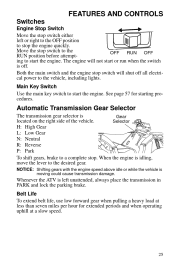
... the vehicle. Belt Life To extend belt life, use low forward gear when pulling a heavy load at less than seven miles per hour for starting procedures. FEATURES AND CONTROLS Switches Engine Stop Switch Move the stop switch either left unattended, always place the transmission in PARK and lock the parking brake. Move the stop . The engine will shut off . Automatic Transmission Gear Selector The transmission gear selector is idling, move the lever to start the engine. Whenever...
... the vehicle. Belt Life To extend belt life, use low forward gear when pulling a heavy load at less than seven miles per hour for starting procedures. FEATURES AND CONTROLS Switches Engine Stop Switch Move the stop switch either left unattended, always place the transmission in PARK and lock the parking brake. Move the stop . The engine will shut off . Automatic Transmission Gear Selector The transmission gear selector is idling, move the lever to start the engine. Whenever...
Owners Manual
Page 37
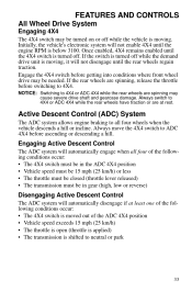
... Control (ADC) System The ADC system allows engine braking to all four of the following conditions occur: • The 4X4 switch is moved out of the ADC 4X4 position • Vehicle speed exceeds 15 mph (25 km/h) • The throttle is open (throttle is applied) • The transmission is shifted to 4X4. NOTICE: Switching to ADC 4X4 before getting into conditions where front wheel drive...
... Control (ADC) System The ADC system allows engine braking to all four of the following conditions occur: • The 4X4 switch is moved out of the ADC 4X4 position • Vehicle speed exceeds 15 mph (25 km/h) • The throttle is open (throttle is applied) • The transmission is shifted to 4X4. NOTICE: Switching to ADC 4X4 before getting into conditions where front wheel drive...
Owners Manual
Page 39
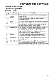
... this warning appears. FEATURES AND CONTROLS Instrument Cluster Digital/Analog Gauge Indicator Lamps Lamp Indicates Vehicle Speed Over Temperature Condition When standard mode is selected, speed displays in miles per hour. EPS Warning This indicator illuminates when the key is started. See your authorized POLARIS dealer for service. This lamp flashes to the ON position and goes off when the engine is turned to indicate an overheated engine. If the light...
... this warning appears. FEATURES AND CONTROLS Instrument Cluster Digital/Analog Gauge Indicator Lamps Lamp Indicates Vehicle Speed Over Temperature Condition When standard mode is selected, speed displays in miles per hour. EPS Warning This indicator illuminates when the key is started. See your authorized POLARIS dealer for service. This lamp flashes to the ON position and goes off when the engine is turned to indicate an overheated engine. If the light...

Owners Manual
Page 41
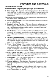
... fuel sensor circuit. Refuel immediately. This area displays odometer, trip meter, engine hour meter, engine speed and programmable service hour interval. 4. Fuel Gauge Display - Active Descent Control Display - If the engine is active. This icon displays when the 4X4 system is engaged (switch is activated. Service Reminder Display - See page 39 for resetting instructions. 6. Gear Display - See your dealer for 5-10 seconds. FEATURES AND CONTROLS Instrument Cluster...
... fuel sensor circuit. Refuel immediately. This area displays odometer, trip meter, engine hour meter, engine speed and programmable service hour interval. 4. Fuel Gauge Display - Active Descent Control Display - If the engine is active. This icon displays when the 4X4 system is engaged (switch is activated. Service Reminder Display - See page 39 for resetting instructions. 6. Gear Display - See your dealer for 5-10 seconds. FEATURES AND CONTROLS Instrument Cluster...
Owners Manual
Page 47
... gear indicator display, when the transmission is turned off, press the MODE button. Neutral Indicator - This indicator illuminates when the lights are set to indicate an overheated engine. Serious engine damage could result. If this warning appears. The vehicle should be brought to displaying in the fuel sensor circuit. This icon flashes to high beam. 6. Check Engine Warning - FEATURES AND CONTROLS Instrument Cluster Multi-Function Display (MFD) Gauge (EPS Models) 4. Fuel Gauge...
... gear indicator display, when the transmission is turned off, press the MODE button. Neutral Indicator - This indicator illuminates when the lights are set to indicate an overheated engine. Serious engine damage could result. If this warning appears. The vehicle should be brought to displaying in the fuel sensor circuit. This icon flashes to high beam. 6. Check Engine Warning - FEATURES AND CONTROLS Instrument Cluster Multi-Function Display (MFD) Gauge (EPS Models) 4. Fuel Gauge...

Owners Manual
Page 52
... 3 4 3 4 16 0 3 4 3 4 8 4 3 2 5 3 5 3 5 3 5 3 Intake Air Temperature Sensor Manifold Absolute Pressure Sensor Crankshaft Position Sensor Gear Sensor Signal Injector 1 (MAG) Ignition Coil Primary Driver 1 (MAG) Fuel Pump Driver Circuit Fan Relay Driver Circuit 48 Short-to-Battery: The wire leading from the item listed in the chart to the electronic control unit is shorted to ground between the electronic control unit and the item listed in the chart. SPORTSMAN 550/550EPS Diagnostic Codes Component Throttle Position Sensor Engine Temperature Sensor Condition Voltage Too...
... 3 4 3 4 16 0 3 4 3 4 8 4 3 2 5 3 5 3 5 3 5 3 Intake Air Temperature Sensor Manifold Absolute Pressure Sensor Crankshaft Position Sensor Gear Sensor Signal Injector 1 (MAG) Ignition Coil Primary Driver 1 (MAG) Fuel Pump Driver Circuit Fan Relay Driver Circuit 48 Short-to-Battery: The wire leading from the item listed in the chart to the electronic control unit is shorted to ground between the electronic control unit and the item listed in the chart. SPORTSMAN 550/550EPS Diagnostic Codes Component Throttle Position Sensor Engine Temperature Sensor Condition Voltage Too...

Owners Manual
Page 54
... 523 523 651 651 651 652 652 652 1268 1269 1347 1347 1347 1071 1071 1071 634 634 634 634 1321 1321 1321 FMI 3 4 3 4 16 0 3 4 3 4 2 8 2 8 2 4 3 2 5 3 4 5 3 4 3 3 5 3 4 5 3 4 5 3 4 7 5 3 4 Intake Air Temperature Sensor Manifold Absolute Pressure Sensor Crankshaft Position Sensor Vehicle Speed Signal Gear Sensor Signal Injector 1 (MAG) (SDI Part Load) Injector 2 (PTO) (SDI Part Load) Ignition Coil Primary Driver 1 (MAG) Ignition Coil Primary Driver 2 (PTO) Fuel Pump Driver Circuit Fan Relay Driver Circuit Idle Air Control Starter Enable Circuit 50
... 523 523 651 651 651 652 652 652 1268 1269 1347 1347 1347 1071 1071 1071 634 634 634 634 1321 1321 1321 FMI 3 4 3 4 16 0 3 4 3 4 2 8 2 8 2 4 3 2 5 3 4 5 3 4 3 3 5 3 4 5 3 4 5 3 4 7 5 3 4 Intake Air Temperature Sensor Manifold Absolute Pressure Sensor Crankshaft Position Sensor Vehicle Speed Signal Gear Sensor Signal Injector 1 (MAG) (SDI Part Load) Injector 2 (PTO) (SDI Part Load) Ignition Coil Primary Driver 1 (MAG) Ignition Coil Primary Driver 2 (PTO) Fuel Pump Driver Circuit Fan Relay Driver Circuit Idle Air Control Starter Enable Circuit 50

Owners Manual
Page 55
... Bus Steering Torque Sensor T2 Par- FEATURES AND CONTROLS Instrument Cluster Diagnostic Display Code Definitions SPORTSMAN 850 XP/850 XP EPS Diagnostic Codes Component Chassis Relay Condition Driver Circuit Open/Grounded Driver Circuit Short to B+ Driver Circuit Grounded Driver Circuit Open/Grounded Driver Circuit Short to B+ Driver Circuit Grounded Voltage Too High Voltage Too low Voltage Too High Voltage Too Low Signal Out of Range Throttle Stuck Driver Circuit Open/Grounded Driver Circuit Short to B+ Driver Circuit Grounded Speed Too High Speed Too...
... Bus Steering Torque Sensor T2 Par- FEATURES AND CONTROLS Instrument Cluster Diagnostic Display Code Definitions SPORTSMAN 850 XP/850 XP EPS Diagnostic Codes Component Chassis Relay Condition Driver Circuit Open/Grounded Driver Circuit Short to B+ Driver Circuit Grounded Driver Circuit Open/Grounded Driver Circuit Short to B+ Driver Circuit Grounded Voltage Too High Voltage Too low Voltage Too High Voltage Too Low Signal Out of Range Throttle Stuck Driver Circuit Open/Grounded Driver Circuit Short to B+ Driver Circuit Grounded Speed Too High Speed Too...

Owners Manual
Page 57
... the time it takes to use . Fill the fuel tank with vehicle operation and handling. 4. Add oil if necessary to maintain the level between the safe and add marks. 3. Drive slowly at 20 hours, one month or 500 miles (800 km), whichever comes first. Vary the throttle positions. Perform regular checks on fluid levels, controls and areas outlined on your new POLARIS ATV...
... the time it takes to use . Fill the fuel tank with vehicle operation and handling. 4. Add oil if necessary to maintain the level between the safe and add marks. 3. Drive slowly at 20 hours, one month or 500 miles (800 km), whichever comes first. Vary the throttle positions. Perform regular checks on fluid levels, controls and areas outlined on your new POLARIS ATV...

Owners Manual
Page 73
... maintain stable driving conditions. When operating over rough or hilly terrain, reduce speed and cargo weight to the vehicle and will void your POLARIS ATV. If towing a load, reduce rear rack cargo weight by the amount of tongue weight. • The combination of rear rack cargo weight and tongue weight must not exceed the rear rack capacity. • The total load (operator, accessories, cargo and weight on the rear rack) and mounted as...
... maintain stable driving conditions. When operating over rough or hilly terrain, reduce speed and cargo weight to the vehicle and will void your POLARIS ATV. If towing a load, reduce rear rack cargo weight by the amount of tongue weight. • The combination of rear rack cargo weight and tongue weight must not exceed the rear rack capacity. • The total load (operator, accessories, cargo and weight on the rear rack) and mounted as...

Owners Manual
Page 79
... M 12 M 12 M 12 M X Wiring n Clutches (drive 100 H 100 H 200 H 200 H 300 H 1000 H 12 M 12 M 24 M 24 M 36 M - adjust when parts are replaced Adjust as needed 1000 (1600) Inspect for leaks at tank cap, lines, filter, pump; apply dielectric grease to connectors subjected to water, mud, etc. 1000 (1600) Inspect; and driven) n Front wheel bearings n Brake fluid X ADC fluid n Spark arrestor nE Valve clearance n Toe adjustment Headlight aim 75 adjust...
... M 12 M 12 M 12 M X Wiring n Clutches (drive 100 H 100 H 200 H 200 H 300 H 1000 H 12 M 12 M 24 M 24 M 36 M - adjust when parts are replaced Adjust as needed 1000 (1600) Inspect for leaks at tank cap, lines, filter, pump; apply dielectric grease to connectors subjected to water, mud, etc. 1000 (1600) Inspect; and driven) n Front wheel bearings n Brake fluid X ADC fluid n Spark arrestor nE Valve clearance n Toe adjustment Headlight aim 75 adjust...

Owners Manual
Page 101
Lift the pod cover and disconnect the speedometer harnesses from your skin leaves a residue, causing a hot spot that will shorten the life of the lamp. Reassemble the pod. 97 Headlight and taillight lenses become dirty during normal operation. Oil from the speedometer. Remove the five (5) headlight pod screws. 2. Install the new lamp. MAINTENANCE Lights Poor lighting can cause burns to...
Lift the pod cover and disconnect the speedometer harnesses from your skin leaves a residue, causing a hot spot that will shorten the life of the lamp. Reassemble the pod. 97 Headlight and taillight lenses become dirty during normal operation. Oil from the speedometer. Remove the five (5) headlight pod screws. 2. Install the new lamp. MAINTENANCE Lights Poor lighting can cause burns to...

Owners Manual
Page 102
... center of the headlight and make the adjustment. 1. Start the engine. Observe the headlight aim on the seat when measuring. 5. Turn the headlight switch to the desired position, then tighten the screw. 98 The most intense part of Screw the headlight pod. To adjust the beam, loosen the screw. Include rider weight on the wall. Place the transmission in PARK. 25 ft. (7.6 m) Lamp Center...
... center of the headlight and make the adjustment. 1. Start the engine. Observe the headlight aim on the seat when measuring. 5. Turn the headlight switch to the desired position, then tighten the screw. 98 The most intense part of Screw the headlight pod. To adjust the beam, loosen the screw. Include rider weight on the wall. Place the transmission in PARK. 25 ft. (7.6 m) Lamp Center...

Owners Manual
Page 104
Use a small screwdriver to remove the o-rings from the locking tabs. 6. Pull the headlight housing up and out of the pod. 7. Remove the five (5) headlight pod screws. 2. Unplug the headlamp from the speedometer. 3. Carefully pull the assembly up to install the new housing and reassemble the pod. 100 Reverse the steps to release it from the headlight mounting tabs. 5. Lift the pod cover and disconnect the speedometer harnesses from the wiring harness. 4. MAINTENANCE Lights Headlight Housing Replacement 1.
Use a small screwdriver to remove the o-rings from the locking tabs. 6. Pull the headlight housing up and out of the pod. 7. Remove the five (5) headlight pod screws. 2. Unplug the headlamp from the speedometer. 3. Carefully pull the assembly up to install the new housing and reassemble the pod. 100 Reverse the steps to release it from the headlight mounting tabs. 5. Lift the pod cover and disconnect the speedometer harnesses from the wiring harness. 4. MAINTENANCE Lights Headlight Housing Replacement 1.

Owners Manual
Page 105
... light for proper operation. Remove the headlamp and install the new headlamp. 3. Remove the harness connector from the headlight assembly. 2. Turn the back of the headlight harness counterclockwise and pull the harness assembly away from the back of the light assembly. 2. Harness Taillight/Brakelight Lamp Replacement Taillight 101 MAINTENANCE Lights Lower Headlamp Replacement 1. Reinstall the harness connector. 5. Turn the lamp counterclockwise to secure the headlamp. 1. Reinstall the harness assembly into the headlight assembly...
... light for proper operation. Remove the headlamp and install the new headlamp. 3. Remove the harness connector from the headlight assembly. 2. Turn the back of the headlight harness counterclockwise and pull the harness assembly away from the back of the light assembly. 2. Harness Taillight/Brakelight Lamp Replacement Taillight 101 MAINTENANCE Lights Lower Headlamp Replacement 1. Reinstall the harness connector. 5. Turn the lamp counterclockwise to secure the headlamp. 1. Reinstall the harness assembly into the headlight assembly...

Owners Manual
Page 121
... the engine or exhaust system. Replacement safety labels are provided by POLARIS at the following items: • Wheel bearings • Electrical components • Radiator • Switches and controls • Transmission seals • Fuel system components • Cab and body panels • Labels and decals If an informational or graphic label becomes illegible or comes off, contact your vehicle. • Always use of your POLARIS dealer to purchase a replacement. Grease...
... the engine or exhaust system. Replacement safety labels are provided by POLARIS at the following items: • Wheel bearings • Electrical components • Radiator • Switches and controls • Transmission seals • Fuel system components • Cab and body panels • Labels and decals If an informational or graphic label becomes illegible or comes off, contact your vehicle. • Always use of your POLARIS dealer to purchase a replacement. Grease...

Owners Manual
Page 130
... Bore x Stroke 96.6 x 75 Alternator Output 490w @ 1350 RPM/Peak 630w Compression Ratio 9.6:1 Starting System Electric Ignition System Electronic Fuel Injection Idle RPM** 1750 +/- 50 Ignition Timing 13 +/- 3 BTDC @ 1350 RPM, Engine warm Spark Plug / Gap NGK BKR6E / .035 in. (0.9 mm) Lubrication System Wet Sump Driving System Type Automatic PVT (POLARIS Variable Transmission) Front Suspension Dual a-arm with 9.2" (23 cm) travel Rear Suspension Progressive rate with 10.2" (26 cm) travel...
... Bore x Stroke 96.6 x 75 Alternator Output 490w @ 1350 RPM/Peak 630w Compression Ratio 9.6:1 Starting System Electric Ignition System Electronic Fuel Injection Idle RPM** 1750 +/- 50 Ignition Timing 13 +/- 3 BTDC @ 1350 RPM, Engine warm Spark Plug / Gap NGK BKR6E / .035 in. (0.9 mm) Lubrication System Wet Sump Driving System Type Automatic PVT (POLARIS Variable Transmission) Front Suspension Dual a-arm with 9.2" (23 cm) travel Rear Suspension Progressive rate with 10.2" (26 cm) travel...

Owners Manual
Page 132
... Engine EHO850LE Displacement 850 cc Bore x Stroke 87 x 71.5 Alternator Output 475w @1200 RPM/Peak 630w Compression Ratio 11:1 Starting System Electric Ignition System Electronic Fuel Injection Idle RPM 1200 +/- 100 Ignition Timing 6 +/- 5 BTDC @ 1200 RPM, Engine warm Spark Plug Type / Gap Champion REA8MCX / .035 in. (0.9 mm) Lubrication System Wet Sump Driving System Type Automatic PVT (POLARIS Variable Transmission) Front Suspension Dual a-arm with 9.2" (23 cm) travel Rear Suspension Progressive rate with...
... Engine EHO850LE Displacement 850 cc Bore x Stroke 87 x 71.5 Alternator Output 475w @1200 RPM/Peak 630w Compression Ratio 11:1 Starting System Electric Ignition System Electronic Fuel Injection Idle RPM 1200 +/- 100 Ignition Timing 6 +/- 5 BTDC @ 1200 RPM, Engine warm Spark Plug Type / Gap Champion REA8MCX / .035 in. (0.9 mm) Lubrication System Wet Sump Driving System Type Automatic PVT (POLARIS Variable Transmission) Front Suspension Dual a-arm with 9.2" (23 cm) travel Rear Suspension Progressive rate with...

Owners Manual
Page 141
... considered emission-related components for exhaust emissions: • Aftertreatment devices • Crankcase ventilation valves • Sensors • Electronic control units The following parts are considered emission-related components for evaporative emissions Fuel Tank Fuel Cap Fuel Line Fuel Line Fittings Clamps* Pressure Relief Valves* Control Valves* Control Solenoids* Electronic Controls Vacuum Control Diaphragms* Control Cables* Control Linkages* Purge Valves Vapor Hoses Liquid/Vapor Separator Carbon Canister Canister Mounting Brackets Carburetor Purge Port Connector...
... considered emission-related components for exhaust emissions: • Aftertreatment devices • Crankcase ventilation valves • Sensors • Electronic control units The following parts are considered emission-related components for evaporative emissions Fuel Tank Fuel Cap Fuel Line Fuel Line Fittings Clamps* Pressure Relief Valves* Control Valves* Control Solenoids* Electronic Controls Vacuum Control Diaphragms* Control Cables* Control Linkages* Purge Valves Vapor Hoses Liquid/Vapor Separator Carbon Canister Canister Mounting Brackets Carburetor Purge Port Connector...

Owners Manual
Page 148
...No Passenger" Warning...22 Age 16 Warning...21 Clutch Cover Warning...23 Discretionary Warning...21 General Warning ...20 Hitch Capacity Label ...23 Rack Warning, Front and Rear 23 Reverse Override Warning ...21 Tire Pressure/Load Warning . . 22 Safety Training ...7 Safety Warnings...10-19 Severe Use ...72 Side Panel Removal...91 Sidehilling ...62 Signal Words ...4 Spark Arrestor ...105 Spark Plug Inspection ...102-103 Spark Plug Recommendations...102 Spark Plugs ...102-103 Speedometer ...34 Spring Adjustment, Shock ...109 Starting the Engine ...57 V Vehicle Identification Numbers...6 Vehicle...
...No Passenger" Warning...22 Age 16 Warning...21 Clutch Cover Warning...23 Discretionary Warning...21 General Warning ...20 Hitch Capacity Label ...23 Rack Warning, Front and Rear 23 Reverse Override Warning ...21 Tire Pressure/Load Warning . . 22 Safety Training ...7 Safety Warnings...10-19 Severe Use ...72 Side Panel Removal...91 Sidehilling ...62 Signal Words ...4 Spark Arrestor ...105 Spark Plug Inspection ...102-103 Spark Plug Recommendations...102 Spark Plugs ...102-103 Speedometer ...34 Spring Adjustment, Shock ...109 Starting the Engine ...57 V Vehicle Identification Numbers...6 Vehicle...