Installation Guide
Page 2
...Chapter 2 Smart Interface Cards (Router 5000 2-1 2.1 ROUTER 1-PORT 10/100 SIC 2-1 2.1.1 Interface Attributes 2-1 2.1.2 Interface Cable ...2-2 2.1.3 Connecting the Interface Cable 2-2 2.2 ROUTER 1-PORT SERIAL SIC 2-3 2.2.1 Introduction...2-3 2.2.2 Appearance ...2-4 2.2.3 Interface Attributes 2-5 2.2.4 Interface LEDs...2-6 2.2.5 Interface Cable ...2-6 2.2.6 Connecting Interface Cable 2-8 2.3 ROUTER 2-PORT ISDN-S/T SIC and ROUTER 2-PORT ISDN-U SIC 2-9 2.3.1 Introduction...2-9 2.3.2 Appearance ...2-9 2.3.3 Interface Attributes 2-10 2.3.4 Interface LEDs...2-10 2.3.5 Interface Cable ...2-11...
...Chapter 2 Smart Interface Cards (Router 5000 2-1 2.1 ROUTER 1-PORT 10/100 SIC 2-1 2.1.1 Interface Attributes 2-1 2.1.2 Interface Cable ...2-2 2.1.3 Connecting the Interface Cable 2-2 2.2 ROUTER 1-PORT SERIAL SIC 2-3 2.2.1 Introduction...2-3 2.2.2 Appearance ...2-4 2.2.3 Interface Attributes 2-5 2.2.4 Interface LEDs...2-6 2.2.5 Interface Cable ...2-6 2.2.6 Connecting Interface Cable 2-8 2.3 ROUTER 2-PORT ISDN-S/T SIC and ROUTER 2-PORT ISDN-U SIC 2-9 2.3.1 Introduction...2-9 2.3.2 Appearance ...2-9 2.3.3 Interface Attributes 2-10 2.3.4 Interface LEDs...2-10 2.3.5 Interface Cable ...2-11...
Installation Guide
Page 4
... 3.6.2 Interface Attributes 3-22 3.6.3 Interface LEDs...3-23 3.6.4 Interface Cable ...3-23 3.6.5 Connecting the Interface Cable 3-24 3.7 ROUTER 2 AND 4-PORT ENHANCED SERIAL MIM 3-25 3.7.1 Introduction...3-25 3.7.2 Interface Attributes 3-26 3.7.3 Interface LEDs...3-27 3.7.4 Interface Cable ...3-28 3.7.5 Connecting the Interface Cable 3-31 3.8 Router 2 and 4-Port CE1/PRI MIM Modules 3-32 3.8.1 Introduction...3-32 3.8.2 Interface Attributes 3-32 3.8.3 Interface LEDs...3-33 3.8.4 Interface Cable ...3-34 3.8.5 Internal DIP Switches 3-37 3.8.6 Connecting the Interface Cable 3-38 3.9 Router...
... 3.6.2 Interface Attributes 3-22 3.6.3 Interface LEDs...3-23 3.6.4 Interface Cable ...3-23 3.6.5 Connecting the Interface Cable 3-24 3.7 ROUTER 2 AND 4-PORT ENHANCED SERIAL MIM 3-25 3.7.1 Introduction...3-25 3.7.2 Interface Attributes 3-26 3.7.3 Interface LEDs...3-27 3.7.4 Interface Cable ...3-28 3.7.5 Connecting the Interface Cable 3-31 3.8 Router 2 and 4-Port CE1/PRI MIM Modules 3-32 3.8.1 Introduction...3-32 3.8.2 Interface Attributes 3-32 3.8.3 Interface LEDs...3-33 3.8.4 Interface Cable ...3-34 3.8.5 Internal DIP Switches 3-37 3.8.6 Connecting the Interface Cable 3-38 3.9 Router...
Installation Guide
Page 6
... 10/100/1000 MIM 3-64 3.18.1 Introduction...3-64 3.18.2 Interface Attributes 3-64 3.18.3 Interface Cable ...3-65 3.18.4 Connecting the Interface Cable 3-65 Chapter 4 Flexible Interface Cards (Router 6000 3-65 4.1.1 Router 2-Port 10/100 FIC 3-65 4.1.2 Introduction...3-65 4.1.3 Interface Attributes 3-65 4.1.4 Panel and Interface LEDs 3-65 4.1.5 Interface Cable ...3-65 4.1.6 Connecting the Interface Cable 3-65 4.1.7 Router 1-Port 100FX MM FIC/100FX SM FIC 3-65 4.1.8 Introduction...
... 10/100/1000 MIM 3-64 3.18.1 Introduction...3-64 3.18.2 Interface Attributes 3-64 3.18.3 Interface Cable ...3-65 3.18.4 Connecting the Interface Cable 3-65 Chapter 4 Flexible Interface Cards (Router 6000 3-65 4.1.1 Router 2-Port 10/100 FIC 3-65 4.1.2 Introduction...3-65 4.1.3 Interface Attributes 3-65 4.1.4 Panel and Interface LEDs 3-65 4.1.5 Interface Cable ...3-65 4.1.6 Connecting the Interface Cable 3-65 4.1.7 Router 1-Port 100FX MM FIC/100FX SM FIC 3-65 4.1.8 Introduction...
Installation Guide
Page 12
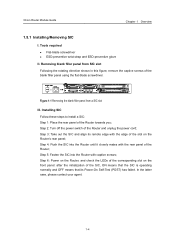
... off the power switch of the Router towards you; Step 3: Take out the SIC and align its Power-On Self-Test (POST) has failed. Step 5: Fasten the SIC into the Router until it closely mates with the rear panel of the corresponding slot on the Router's rear panel;...Flat-blade screwdriver z ESD-preventive wrist strap and ESD-preventive glove II. Step 6: Power on the Router, and check the LEDs of the Router; In the latter case, please contact your agent. 1-4 3Com Router Module Guide Chapter 1 Overview 1.5.1 Installing/Removing SIC I. Removing blank filler panel from a SIC slot ...
... off the power switch of the Router towards you; Step 3: Take out the SIC and align its Power-On Self-Test (POST) has failed. Step 5: Fasten the SIC into the Router until it closely mates with the rear panel of the corresponding slot on the Router's rear panel;...Flat-blade screwdriver z ESD-preventive wrist strap and ESD-preventive glove II. Step 6: Power on the Router, and check the LEDs of the Router; In the latter case, please contact your agent. 1-4 3Com Router Module Guide Chapter 1 Overview 1.5.1 Installing/Removing SIC I. Removing blank filler panel from a SIC slot ...
Installation Guide
Page 13
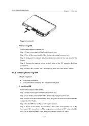
... a MIM: Step 1: Place the rear panel of the Router and unplug the power cord; Step 3: Unplug all the network interface cables connected to remove a SIC: Step 1: Place the rear panel of the Router chassis. 1.5.2 Installing/Removing MIM I. Step 2: Turn off the power switch of the Router towards you ; 3Com Router Module Guide Chapter 1 Overview Figure 1-2 Installing SIC...
... a MIM: Step 1: Place the rear panel of the Router and unplug the power cord; Step 3: Unplug all the network interface cables connected to remove a SIC: Step 1: Place the rear panel of the Router chassis. 1.5.2 Installing/Removing MIM I. Step 2: Turn off the power switch of the Router towards you ; 3Com Router Module Guide Chapter 1 Overview Figure 1-2 Installing SIC...

Installation Guide
Page 14
Step 4: Loosen the captive screws at both sides of the Router; Step 3: Unplug all interface cables from the bottom of the router. 1.6 Troubleshooting 3Com 5000 Routers LEDs, indicate the state of the module as follows: After the installation of a SIC/MIM, turn on the power and view the corresponding ... unplug the power cord; Removing MIM Follow these steps to remove a MIM: Step 1: Place the rear panel of the Router towards you ; Step 2: Turn off the power switch of the SIC/MIM has failed. 1-6 Step 5: Pull the MIM towards you until it is completely separated from the rear panel ...
Step 4: Loosen the captive screws at both sides of the Router; Step 3: Unplug all interface cables from the bottom of the router. 1.6 Troubleshooting 3Com 5000 Routers LEDs, indicate the state of the module as follows: After the installation of a SIC/MIM, turn on the power and view the corresponding ... unplug the power cord; Removing MIM Follow these steps to remove a MIM: Step 1: Place the rear panel of the Router towards you ; Step 2: Turn off the power switch of the SIC/MIM has failed. 1-6 Step 5: Pull the MIM towards you until it is completely separated from the rear panel ...
Installation Guide
Page 17
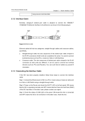
3Com Router Module Guide being received or/and transmitted. You can be used to connect terminal devices (such as PCs, routers) to connect two terminal devices (such as shown in the following figure: Figure 2-2 Ethernet cable Ethernet cables fall into two...2 Smart Interface Cards 2.1.2 Interface Cable Normally, category-5 twisted pair cable is operating normally and OFF means that the SIC is adopted to connect the 10BASE-T /100BASE-TX Ethernet interface to a Hub or LAN Switch using a crossover cable and to the Ethernet, as PCs and Routers). Step 2: Power on the Router and check...
3Com Router Module Guide being received or/and transmitted. You can be used to connect terminal devices (such as PCs, routers) to connect two terminal devices (such as shown in the following figure: Figure 2-2 Ethernet cable Ethernet cables fall into two...2 Smart Interface Cards 2.1.2 Interface Cable Normally, category-5 twisted pair cable is operating normally and OFF means that the SIC is adopted to connect the 10BASE-T /100BASE-TX Ethernet interface to a Hub or LAN Switch using a crossover cable and to the Ethernet, as PCs and Routers). Step 2: Power on the Router and check...
Installation Guide
Page 19
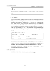
The DCE device provides the synchronous clock and specifies the communicating rate. Generally, the Router is used as DDN, frame relay, or X.25 switch. 2.2.2 Appearance ROUTER 1-PORT SERIAL SIC is illustrated in the following table may also help you to identify the ..., CSU/DSU Asynchronous serial interface is used and the interface operates in the DCE mode. DTE and DCE The synchronous serial interface supports both DTE (Data Terminal Equipment) and DCE (Data Circuit-terminating Equipment) operating modes. 3Com Router Module Guide Chapter 2 Smart Interface Cards Caution: The baud rate ...
The DCE device provides the synchronous clock and specifies the communicating rate. Generally, the Router is used as DDN, frame relay, or X.25 switch. 2.2.2 Appearance ROUTER 1-PORT SERIAL SIC is illustrated in the following table may also help you to identify the ..., CSU/DSU Asynchronous serial interface is used and the interface operates in the DCE mode. DTE and DCE The synchronous serial interface supports both DTE (Data Terminal Equipment) and DCE (Data Circuit-terminating Equipment) operating modes. 3Com Router Module Guide Chapter 2 Smart Interface Cards Caution: The baud rate ...
Installation Guide
Page 29
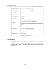
... following figure: 2-14 By default, all the 8 positions of impedance through an 8BIT DIP switch. 3Com Router Module Guide Chapter 2 Smart Interface Cards Table 2-9 Interface attributes of ROUTER 1-PORT FRACTIONAL E1 SIC Attribute Description Connector type DB15 Number of connectors 1 Interface standard G.703, G.704 Interface rate 2.048Mbps Cable type 75-ohm non-balanced coaxial cable (DB15 to BNC) 120...
... following figure: 2-14 By default, all the 8 positions of impedance through an 8BIT DIP switch. 3Com Router Module Guide Chapter 2 Smart Interface Cards Table 2-9 Interface attributes of ROUTER 1-PORT FRACTIONAL E1 SIC Attribute Description Connector type DB15 Number of connectors 1 Interface standard G.703, G.704 Interface rate 2.048Mbps Cable type 75-ohm non-balanced coaxial cable (DB15 to BNC) 120...
Installation Guide
Page 30
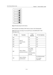
... OFF: RxShield ungrounding 2-15 3Com Router Module Guide on 1 2 3 4 5 6 7 8 Chapter 2 Smart Interface Cards Figure 2-14 Default setting of the DIP switches 8BIT description and settings of DIP switch are given in the following table: Table 2-10 Description and settings of the internal DIP switch of SIC-ERRI/ROUTER 1-PORT FRACTIONAL E1 SIC DIP switch Description 75 -ohm impedance 120...
... OFF: RxShield ungrounding 2-15 3Com Router Module Guide on 1 2 3 4 5 6 7 8 Chapter 2 Smart Interface Cards Figure 2-14 Default setting of the DIP switches 8BIT description and settings of DIP switch are given in the following table: Table 2-10 Description and settings of the internal DIP switch of SIC-ERRI/ROUTER 1-PORT FRACTIONAL E1 SIC DIP switch Description 75 -ohm impedance 120...
Installation Guide
Page 31
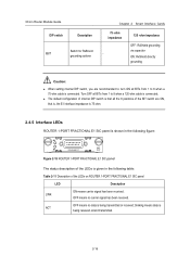
... or received; OFF means no carrier signal has been received. 3Com Router Module Guide DIP switch Description Switch for RxShield 8BIT grounding options Chapter 2 Smart Interface Cards 75 -ohm impedance - 120 -ohm impedance OFF: RxShield grounding via capacitor ON: RxShield directly grounding Caution: z When setting internal DIP switch, you are recommended to: turn ON all the 8 positions...
... or received; OFF means no carrier signal has been received. 3Com Router Module Guide DIP switch Description Switch for RxShield 8BIT grounding options Chapter 2 Smart Interface Cards 75 -ohm impedance - 120 -ohm impedance OFF: RxShield grounding via capacitor ON: RxShield directly grounding Caution: z When setting internal DIP switch, you are recommended to: turn ON all the 8 positions...
Installation Guide
Page 33
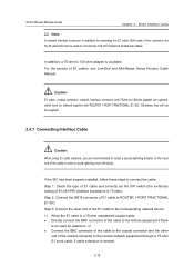
... coaxial connector, network interface connector and 75ohm-to-120ohm adapter are recommended to connect the cable: Step 1: Check the type of E1 cable and correctly set the DIP switch (the ex-factory setting of E1 cables, see Low-End and Mid-Range Series Routers Cable Manual. If ...arrester on the input end of the connector are RJ-45 jacks that can be ordered together with ROUTER 1-PORT FRACTIONAL E1 SIC. 3Com Router Module Guide Chapter 2 Smart Interface Cards Note: A network interface connector is available for extension, or z Connect the BNC connector of the cable to the coaxial ...
... coaxial connector, network interface connector and 75ohm-to-120ohm adapter are recommended to connect the cable: Step 1: Check the type of E1 cable and correctly set the DIP switch (the ex-factory setting of E1 cables, see Low-End and Mid-Range Series Routers Cable Manual. If ...arrester on the input end of the connector are RJ-45 jacks that can be ordered together with ROUTER 1-PORT FRACTIONAL E1 SIC. 3Com Router Module Guide Chapter 2 Smart Interface Cards Note: A network interface connector is available for extension, or z Connect the BNC connector of the cable to the coaxial ...
Installation Guide
Page 49
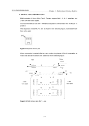
...E&M modules of RJ-45 receptacles at router side and at the switch side are shown in practice. wire voice signal R1 R1 4 Figure 3-10 E&M interface cable (Bell V 4-wire) 3-5 It is recommended to use Bell V 4-wire voice signal to communicate with the Router in the following figure, numbered 1 to...wire voice signal R0 R0 3 T1 T1 5 4- The sequence of E&M RJ-45 pins is made in Bell V 4-wire mode, the pinouts of 3Com 5000 Family Routers support Bell I, II, III, V switches, and 2-wire & 4-wire voice signals. 3Com Router Module Guide Chapter 3 Multifunctional Interface Modules II.
...E&M modules of RJ-45 receptacles at router side and at the switch side are shown in practice. wire voice signal R1 R1 4 Figure 3-10 E&M interface cable (Bell V 4-wire) 3-5 It is recommended to use Bell V 4-wire voice signal to communicate with the Router in the following figure, numbered 1 to...wire voice signal R0 R0 3 T1 T1 5 4- The sequence of E&M RJ-45 pins is made in Bell V 4-wire mode, the pinouts of 3Com 5000 Family Routers support Bell I, II, III, V switches, and 2-wire & 4-wire voice signals. 3Com Router Module Guide Chapter 3 Multifunctional Interface Modules II.
Installation Guide
Page 50
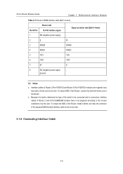
... according to the on-spot conditions or by the router side. 3.1.6 Connecting Interface Cable 3-6 z Because it is hard to determine the type of the switch to the Router. 3Com Router Module Guide Chapter 3 Multifunctional Interface Modules Table 3-3 Pinouts of E&M interface cable (Bell V 4-wire) RJ-45 Pin Router side RJ-45 interface signal Signal at one end. To ensure EMC of...
... according to the on-spot conditions or by the router side. 3.1.6 Connecting Interface Cable 3-6 z Because it is hard to determine the type of the switch to the Router. 3Com Router Module Guide Chapter 3 Multifunctional Interface Modules Table 3-3 Pinouts of E&M interface cable (Bell V 4-wire) RJ-45 Pin Router side RJ-45 interface signal Signal at one end. To ensure EMC of...
Installation Guide
Page 51
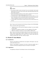
3Com Router Module Guide Chapter 3 Multifunctional Interface Modules Caution: z Some measures are recommended to install a special lightning arrester at the input end of telephone exchange, if you have installed an FXS module; z As provisioned by Bell V, cables for work. z To ensure the EMC of the whole Router, you should be connected to damage interface...structured in the form of the Router; Router E1 Voice Module is the correct port. In practice, the PGND wire of the switch can be formed via the earth ground between the Router and the connected switch. It provides a CE1/PRI ...
3Com Router Module Guide Chapter 3 Multifunctional Interface Modules Caution: z Some measures are recommended to install a special lightning arrester at the input end of telephone exchange, if you have installed an FXS module; z As provisioned by Bell V, cables for work. z To ensure the EMC of the whole Router, you should be connected to damage interface...structured in the form of the Router; Router E1 Voice Module is the correct port. In practice, the PGND wire of the switch can be formed via the earth ground between the Router and the connected switch. It provides a CE1/PRI ...
Installation Guide
Page 64
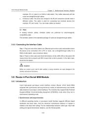
... or LAN switch, use a straight-through cables. I. And the maximum transmission distance of the cable to an Ethernet port on the panel: ON means that a link is present and OFF means that no link is used for connecting two terminal devices (for electromagnetic compatibility sake. 3Com Router Module Guide Chapter 3 Multifunctional Interface Modules example...
... or LAN switch, use a straight-through cables. I. And the maximum transmission distance of the cable to an Ethernet port on the panel: ON means that a link is present and OFF means that no link is used for connecting two terminal devices (for electromagnetic compatibility sake. 3Com Router Module Guide Chapter 3 Multifunctional Interface Modules example...
Installation Guide
Page 66
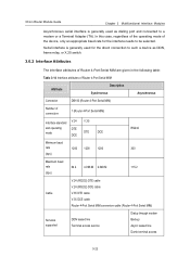
...3Com Router Module Guide Chapter 3 Multifunctional Interface Modules Asynchronous serial interface is generally used as dialing port and connected to such a device as DDN, frame relay, or X.25 switch. 3.6.2 Interface Attributes The interface attributes of Router 4-Port Serial MIM are given in the following table: Table 3-14 Interface attributes of Router 4-Port Serial MIM Attribute Description Synchronous Asynchronous Connector DB100 (Router..., regardless of the operating mode of connectors 1 (Router 4-Port Serial MIM) Interface standard V.24 V.35 and operating mode DTE DTE DCE...
...3Com Router Module Guide Chapter 3 Multifunctional Interface Modules Asynchronous serial interface is generally used as dialing port and connected to such a device as DDN, frame relay, or X.25 switch. 3.6.2 Interface Attributes The interface attributes of Router 4-Port Serial MIM are given in the following table: Table 3-14 Interface attributes of Router 4-Port Serial MIM Attribute Description Synchronous Asynchronous Connector DB100 (Router..., regardless of the operating mode of connectors 1 (Router 4-Port Serial MIM) Interface standard V.24 V.35 and operating mode DTE DTE DCE...
Installation Guide
Page 81
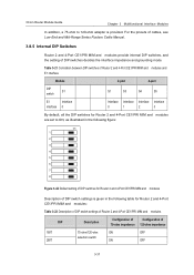
... the pinouts of cables, see Low-End and Mid-Range Series Routers Cable Manual. 3.8.5 Internal DIP Switches Router 2 and 4-Port CE1/PRI MIM and modules provide internal DIP switches, and the setting of DIP switches decides the interface impedance and grounding mode. 3Com Router Module Guide Chapter 3 Multifunctional Interface Modules In addition, a 75-ohm to ON, as illustrated in...
... the pinouts of cables, see Low-End and Mid-Range Series Routers Cable Manual. 3.8.5 Internal DIP Switches Router 2 and 4-Port CE1/PRI MIM and modules provide internal DIP switches, and the setting of DIP switches decides the interface impedance and grounding mode. 3Com Router Module Guide Chapter 3 Multifunctional Interface Modules In addition, a 75-ohm to ON, as illustrated in...
Installation Guide
Page 82
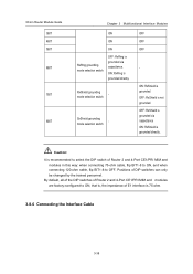
... is grounded directly. ON: RxRing is not grounded. 3Com Router Module Guide 3BIT 4BIT 5BIT 6BIT 7BIT 8BIT Chapter 3 Multifunctional Interface Modules ON ON ON RxRing grounding mode selection switch OFF: RxRing is grounded via capacitance ON: RxShield is recommended to select the DIP switch of Router 2 and 4-Port CE1/PRI MIM and modules in this...
... is grounded directly. ON: RxRing is not grounded. 3Com Router Module Guide 3BIT 4BIT 5BIT 6BIT 7BIT 8BIT Chapter 3 Multifunctional Interface Modules ON ON ON RxRing grounding mode selection switch OFF: RxRing is grounded via capacitance ON: RxShield is recommended to select the DIP switch of Router 2 and 4-Port CE1/PRI MIM and modules in this...
Installation Guide
Page 83
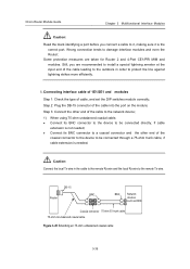
... 75-ohm trunk cable, if cable extension is the correct port. Step 2: Plug the DB-15 connector of cable, and set the DIP switches module correctly; Caution: Connect the local Tx wire in order to protect the line against lightning strikes more efficiently. Some protection measures are recommended... the cable leading to the outdoors in the cable to the remote Rx wire and the local Rx wire to damage interface modules and even the Router; I. 3Com Router Module Guide Chapter 3 Multifunctional Interface Modules Caution: Read the mark identifying a port before you are taken for...
... 75-ohm trunk cable, if cable extension is the correct port. Step 2: Plug the DB-15 connector of cable, and set the DIP switches module correctly; Caution: Connect the local Tx wire in order to protect the line against lightning strikes more efficiently. Some protection measures are recommended... the cable leading to the outdoors in the cable to the remote Rx wire and the local Rx wire to damage interface modules and even the Router; I. 3Com Router Module Guide Chapter 3 Multifunctional Interface Modules Caution: Read the mark identifying a port before you are taken for...