
Getting Started Guide
Page 1
3Com® Switch 4050 and 4060 Getting Started Guide 3C17708, 3C17709 http://www.3com.com/ Part No. DUA1770-9AAA03 Published September 2002
3Com® Switch 4050 and 4060 Getting Started Guide 3C17708, 3C17709 http://www.3com.com/ Part No. DUA1770-9AAA03 Published September 2002
Getting Started Guide
Page 3
... 19 Replaceable Fan Trays 19 Default Settings 20 2 INSTALLING THE SWITCH Package Contents 22 Choosing a Suitable Site 22 Rack-mounting 23 Placing Units On Top of Hardware Features 13 3Com Switch 4050 and 4060 - Front View Detail 14 1000BASE-SX Ports 15 10BASE-T/100BASE-TX... Ports 15 Console Port 15 LEDs 16 3Com Switch 4050 and 4060 - CONTENTS ABOUT THIS GUIDE Conventions 8 Related Documentation 9 Accessing Online Documentation 9 Product Registration 10 Documentation Comments 10 1 INTRODUCING THE 3COM SWITCH 4050 AND 4060 About the 3Com Switch 4050 and 4060 12 Summary of Each Other 24 Creating ...
... 19 Replaceable Fan Trays 19 Default Settings 20 2 INSTALLING THE SWITCH Package Contents 22 Choosing a Suitable Site 22 Rack-mounting 23 Placing Units On Top of Hardware Features 13 3Com Switch 4050 and 4060 - Front View Detail 14 1000BASE-SX Ports 15 10BASE-T/100BASE-TX... Ports 15 Console Port 15 LEDs 16 3Com Switch 4050 and 4060 - CONTENTS ABOUT THIS GUIDE Conventions 8 Related Documentation 9 Accessing Online Documentation 9 Product Registration 10 Documentation Comments 10 1 INTRODUCING THE 3COM SWITCH 4050 AND 4060 About the 3Com Switch 4050 and 4060 12 Summary of Each Other 24 Creating ...

Getting Started Guide
Page 4
Rules For Interconnecting Units 25 The Power-up Sequence 26 Powering-up the 3Com Switch 4050 and 4060 26 Checking for Correct Operation of LEDs 26 Choosing the Correct 10/100/1000 Cables 27 Choosing the correct Fiber cables 28 GBIC Operation 28 ... Connecting to a Front Panel Port 35 Connecting to the Console Port 38 Viewing Automatically Configured IP Information 41 Using 3Com Network Supervisor 41 Connecting to the Console Port 42 Methods of Managing a Switch 44 Command Line Interface Management 44 Web Interface Management 45 SNMP Management 45 Setting Up Command Line Interface Management...
Rules For Interconnecting Units 25 The Power-up Sequence 26 Powering-up the 3Com Switch 4050 and 4060 26 Checking for Correct Operation of LEDs 26 Choosing the Correct 10/100/1000 Cables 27 Choosing the correct Fiber cables 28 GBIC Operation 28 ... Connecting to a Front Panel Port 35 Connecting to the Console Port 38 Viewing Automatically Configured IP Information 41 Using 3Com Network Supervisor 41 Connecting to the Console Port 42 Methods of Managing a Switch 44 Command Line Interface Management 44 Web Interface Management 45 SNMP Management 45 Setting Up Command Line Interface Management...

Getting Started Guide
Page 7
Please refer to the Switch 4050 and 4060. If the information in the release notes that accompanies your product differ from the information in this guide, follow the instructions in its default state. ABOUT THIS GUIDE This guide provides all the information you detailed information on the 3Com World Wide Web site: http://www... in Adobe Acrobat Reader Portable Document Format (PDF) or HTML on how to use the web interface and command line interface to install and use a 3Com® Switch 4050 and 4060 in the release notes.
Please refer to the Switch 4050 and 4060. If the information in the release notes that accompanies your product differ from the information in this guide, follow the instructions in its default state. ABOUT THIS GUIDE This guide provides all the information you detailed information on the 3Com World Wide Web site: http://www... in Adobe Acrobat Reader Portable Document Format (PDF) or HTML on how to use the web interface and command line interface to install and use a 3Com® Switch 4050 and 4060 in the release notes.

Getting Started Guide
Page 9
...Switch. It is supplied on the features supported by each Switch documentation set includes the following online documentation: ■ Switch Implementation Guide (PDF format). ■ Switch Management Interface Reference Guide (HTML format). ■ Other documentation relating to the Switch 4050 and 4060...problems. ■ Switch Implementation Guide This guide contains information on the CD-ROM that accompanies the Switch. Accessing Online ...of the web interface and command line interface commands for the Switch. ■ Release Notes These notes provide information about the ...
...Switch. It is supplied on the features supported by each Switch documentation set includes the following online documentation: ■ Switch Implementation Guide (PDF format). ■ Switch Management Interface Reference Guide (HTML format). ■ Other documentation relating to the Switch 4050 and 4060...problems. ■ Switch Implementation Guide This guide contains information on the CD-ROM that accompanies the Switch. Accessing Online ...of the web interface and command line interface commands for the Switch. ■ Release Notes These notes provide information about the ...

Getting Started Guide
Page 10
...contents page. Product Registration You can register your Switch on the 3Com Web site to receive up-to-date information on the title page) ■ Page number (if appropriate) Example: Part Number DUA1770-9AAA0x 3Com Switch 4050 and 4060 Getting Started Guide Page 21 If your product...: http://support.3com.com/registration/frontpg.pl Documentation Comments Your suggestions are very important to a suitable directory. ■...
...contents page. Product Registration You can register your Switch on the 3Com Web site to receive up-to-date information on the title page) ■ Page number (if appropriate) Example: Part Number DUA1770-9AAA0x 3Com Switch 4050 and 4060 Getting Started Guide Page 21 If your product...: http://support.3com.com/registration/frontpg.pl Documentation Comments Your suggestions are very important to a suitable directory. ■...

Getting Started Guide
Page 11
Front View Detail ■ 3Com Switch 4050 and 4060 - 1 INTRODUCING THE 3COM SWITCH 4050 AND 4060 This chapter contains introductory information about the hardware and the following topics: ■ About the 3Com Switch 4050 and 4060 ■ 3Com Switch 4050 and 4060 - Rear View Detail ■ Default Settings It covers summary information about the 3Com® Switch 4050 and 4060 and how it can be used in your network.
Front View Detail ■ 3Com Switch 4050 and 4060 - 1 INTRODUCING THE 3COM SWITCH 4050 AND 4060 This chapter contains introductory information about the hardware and the following topics: ■ About the 3Com Switch 4050 and 4060 ■ 3Com Switch 4050 and 4060 - Rear View Detail ■ Default Settings It covers summary information about the 3Com® Switch 4050 and 4060 and how it can be used in your network.
Getting Started Guide
Page 12
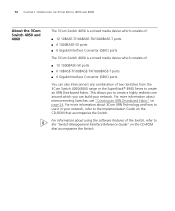
...; 12 10BASE-T/100BASE-TX/1000BASE-T ports ■ 6 1000BASE-SX ports ■ 6 Gigabit Interface Convertor (GBIC) ports The 3Com Switch 4060 is a mixed media device which you can also interconnect any combination of two Switches from the 3Com Switch 4050/4060 range or the SuperStack® 4900 Series to create an XRN Distributed Fabric. For more information about...
...; 12 10BASE-T/100BASE-TX/1000BASE-T ports ■ 6 1000BASE-SX ports ■ 6 Gigabit Interface Convertor (GBIC) ports The 3Com Switch 4060 is a mixed media device which you can also interconnect any combination of two Switches from the 3Com Switch 4050/4060 range or the SuperStack® 4900 Series to create an XRN Distributed Fabric. For more information about...
Getting Started Guide
Page 13
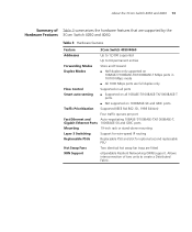
Table 3 Hardware features Feature 3Com Switch 4050/4060 Addresses Up to 12,000 supported Up to create a Distributed...Ethernet Ports 1000BASE-SX and GBIC ports Mounting 19-inch rack or stand-alone mounting Layer 3 Switching Support for wire-speed IP routing Replaceable PSUs Replaceable PSU and slot for optional second replaceable PSU ... of Table 3 summarizes the hardware features that are supported by the Hardware Features 3Com Switch 4050 and 4060. About the 3Com Switch 4050 and 4060 13 Summary of two units to 64 permanent entries Forwarding Modes Store and Forward Duplex...
Table 3 Hardware features Feature 3Com Switch 4050/4060 Addresses Up to 12,000 supported Up to create a Distributed...Ethernet Ports 1000BASE-SX and GBIC ports Mounting 19-inch rack or stand-alone mounting Layer 3 Switching Support for wire-speed IP routing Replaceable PSUs Replaceable PSU and slot for optional second replaceable PSU ... of Table 3 summarizes the hardware features that are supported by the Hardware Features 3Com Switch 4050 and 4060. About the 3Com Switch 4050 and 4060 13 Summary of two units to 64 permanent entries Forwarding Modes Store and Forward Duplex...

Getting Started Guide
Page 14
... P S GBIC 4 GBIC 5 P S 1000SX P 19 20 21 22 23 24 S 19 20 21 22 23 24 P S 3Com Switch 4060 GBIC 6 GBIC LEDs 1000BASE-SX Ports 10BASE-T/100BASE-TX/1000BASE-T Ports 3C17709 1000BASE-SX Ports Front Fan Tray (behind door) Figure 2 3Com Switch 4060 - Either shielded or unshielded data cables with shielded or unshielded jacks can be used as...
... P S GBIC 4 GBIC 5 P S 1000SX P 19 20 21 22 23 24 S 19 20 21 22 23 24 P S 3Com Switch 4060 GBIC 6 GBIC LEDs 1000BASE-SX Ports 10BASE-T/100BASE-TX/1000BASE-T Ports 3C17709 1000BASE-SX Ports Front Fan Tray (behind door) Figure 2 3Com Switch 4060 - Either shielded or unshielded data cables with shielded or unshielded jacks can be used as...

Getting Started Guide
Page 15
.... This offers you to connect a terminal and perform remote or local out-of using GBIC transceivers to provide connectivity between the Switch and remote 1000 Mbps workgroups or to 10 Mbps half duplex, 100 Mbps half duplex, 10 Mbps full duplex or 100 Mbps...setting can be disabled. These ports can be manually configured. Console Port The console port allows you the flexibility of -band management. 3Com Switch 4050 and 4060 - Alternatively, auto-negotiation can be manually configured. 10BASE-T/ 100BASE-TX/ 1000BASE-T Ports The 10BASE-T/100BASE-TX/1000BASE-T ports have MT...
.... This offers you to connect a terminal and perform remote or local out-of using GBIC transceivers to provide connectivity between the Switch and remote 1000 Mbps workgroups or to 10 Mbps half duplex, 100 Mbps half duplex, 10 Mbps full duplex or 100 Mbps...setting can be disabled. These ports can be manually configured. Console Port The console port allows you the flexibility of -band management. 3Com Switch 4050 and 4060 - Alternatively, auto-negotiation can be manually configured. 10BASE-T/ 100BASE-TX/ 1000BASE-T Ports The 10BASE-T/100BASE-TX/1000BASE-T ports have MT...

Getting Started Guide
Page 16
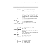
... for Correct Operation of LEDs" on page 26. The Module is enabled. 16 CHAPTER 1: INTRODUCING THE 3COM SWITCH 4050 AND 4060 LEDs Table 4 lists LEDs visible on the front of the Switch, and how to read their status according to create a Distibuted Fabric. No packets are being transmitted/received... No link is installed and supported. The Module is present. A port on the port. Determines the identity of the Switch when interconnected to another Switch to color. The Switch is disabled. A low speed (10/100 Mbps) link is present, but the port is not installed. The Link Status...
... for Correct Operation of LEDs" on page 26. The Module is enabled. 16 CHAPTER 1: INTRODUCING THE 3COM SWITCH 4050 AND 4060 LEDs Table 4 lists LEDs visible on the front of the Switch, and how to read their status according to create a Distibuted Fabric. No packets are being transmitted/received... No link is installed and supported. The Module is present. A port on the port. Determines the identity of the Switch when interconnected to another Switch to color. The Switch is disabled. A low speed (10/100 Mbps) link is present, but the port is not installed. The Link Status...
Getting Started Guide
Page 17
... failed Red flashing Fan Tray has been removed Off Fan Tray fitted and enabled. Yellow The Switch has failed its Power On Self Test and continues to a fault. Off The Switch software does not support Layer 3. 3Com Switch 4050 and 4060 - Front View Detail 17 LED Color Indicates Unit Status LED (cont.) Green flashing The...
... failed Red flashing Fan Tray has been removed Off Fan Tray fitted and enabled. Yellow The Switch has failed its Power On Self Test and continues to a fault. Off The Switch software does not support Layer 3. 3Com Switch 4050 and 4060 - Front View Detail 17 LED Color Indicates Unit Status LED (cont.) Green flashing The...
Getting Started Guide
Page 18
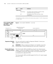
..., ensure the blanking plate is fitted by tightening all screws with a suitable tool. Replaceable Power Supplies (PSUs) The 3Com Switch 4050 and 4060 has a bay for two internal power supplies. Contact your Slot supplier for further information. Contact your supplier for further .... 18 CHAPTER 1: INTRODUCING THE 3COM SWITCH 4050 AND 4060 LED Color Temperature Red flashing Off Indicates The Switch and/or the PSUs are marked '1' for PSU 1 (bottom) and '2' for PSU 2 (top). 3Com Switch 4050 and 4060 - The 3Com Switch 4050 and 4060 support the 3Com AC power supply unit (3C17718)....
..., ensure the blanking plate is fitted by tightening all screws with a suitable tool. Replaceable Power Supplies (PSUs) The 3Com Switch 4050 and 4060 has a bay for two internal power supplies. Contact your Slot supplier for further information. Contact your supplier for further .... 18 CHAPTER 1: INTRODUCING THE 3COM SWITCH 4050 AND 4060 LED Color Temperature Red flashing Off Indicates The Switch and/or the PSUs are marked '1' for PSU 1 (bottom) and '2' for PSU 2 (top). 3Com Switch 4050 and 4060 - The 3Com Switch 4050 and 4060 support the 3Com AC power supply unit (3C17718)....

Getting Started Guide
Page 19
...such circumstances, the unit may be reduced. WARNING: A fan tray can be left without impacting operations. Replaceable Fan Trays The 3Com Switch 4050 and 4060 are advised to the product may overheat and automatically shutdown. If the unit continues to operate with two identical fan trays which ... short time after a single fan failure its airflow and temperature will be powered once it may continue to operate after removal. 3Com Switch 4050 and 4060 - The system must only be affected. Rear View Detail 19 WARNING: The system must be left with either of the two...
...such circumstances, the unit may be reduced. WARNING: A fan tray can be left without impacting operations. Replaceable Fan Trays The 3Com Switch 4050 and 4060 are advised to the product may overheat and automatically shutdown. If the unit continues to operate with two identical fan trays which ... short time after a single fan failure its airflow and temperature will be powered once it may continue to operate after removal. 3Com Switch 4050 and 4060 - The system must only be affected. Rear View Detail 19 WARNING: The system must be left with either of the two...
Getting Started Guide
Page 20
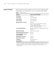
...Filtering Rapid Spanning Tree Protocol Link Aggregation Control Protocol (LACP) Spanning Tree Protocol Smart Auto-sensing IP Address Subnet Mask 3Com Switch 4050/4060 Enabled Auto-negotiated Auto-negotiated Auto-negotiated Enabled High threshold: 3000 broadcast frames per second - If you initialize one of the...unit is already in the range 169.254.1.0 to 169.254.254.255. 20 CHAPTER 1: INTRODUCING THE 3COM SWITCH 4050 AND 4060 Default Settings Table 5 shows the default settings for the 3Com Switch 4050 and 4060. If this default IP address is operating in standalone mode, and/or no other...
...Filtering Rapid Spanning Tree Protocol Link Aggregation Control Protocol (LACP) Spanning Tree Protocol Smart Auto-sensing IP Address Subnet Mask 3Com Switch 4050/4060 Enabled Auto-negotiated Auto-negotiated Auto-negotiated Enabled High threshold: 3000 broadcast frames per second - If you initialize one of the...unit is already in the range 169.254.1.0 to 169.254.254.255. 20 CHAPTER 1: INTRODUCING THE 3COM SWITCH 4050 AND 4060 Default Settings Table 5 shows the default settings for the 3Com Switch 4050 and 4060. If this default IP address is operating in standalone mode, and/or no other...
Getting Started Guide
Page 21
...Suitable Site ■ Rack-mounting ■ Placing Units On Top of this guide. Bevor Sie Komponenten aus dem 3Com Switch 4050 und 4060 entfernen oder dem 3Com Switch 4050 und 4060 hinzufuegen oder Instandhaltungsarbeiten verrichten, lesen Sie die Sicherheitsanweisungen, die in Anhang A in Appendix A of Each Other &#...9632; The Power-up the 3Com® Switch 4050 and 4060. Before installing or removing any components from the 3Com Switch 4050 and 4060 or carrying out any maintenance procedures, you need to install and set up Sequence &#...
...Suitable Site ■ Rack-mounting ■ Placing Units On Top of this guide. Bevor Sie Komponenten aus dem 3Com Switch 4050 und 4060 entfernen oder dem 3Com Switch 4050 und 4060 hinzufuegen oder Instandhaltungsarbeiten verrichten, lesen Sie die Sicherheitsanweisungen, die in Anhang A in Appendix A of Each Other &#...9632; The Power-up the 3Com® Switch 4050 and 4060. Before installing or removing any components from the 3Com Switch 4050 and 4060 or carrying out any maintenance procedures, you need to install and set up Sequence &#...

Getting Started Guide
Page 22
... the vents in the side of the Switch. 3Com recommends that you provide a minimum of the Switch. ■ Air flow is installed in .) clearance. ■ Air temperature around the Switch does not exceed 40 °C (104 °F). 22 CHAPTER 2: INSTALLING THE SWITCH Package Contents ■ 3Com Switch 4050 (3C17708) or Switch 4060 (3C17709) ■ CD-ROM ■ This Guide ■...
... the vents in the side of the Switch. 3Com recommends that you provide a minimum of the Switch. ■ Air flow is installed in .) clearance. ■ Air temperature around the Switch does not exceed 40 °C (104 °F). 22 CHAPTER 2: INSTALLING THE SWITCH Package Contents ■ 3Com Switch 4050 (3C17708) or Switch 4060 (3C17709) ■ CD-ROM ■ This Guide ■...
Getting Started Guide
Page 23
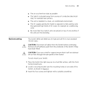
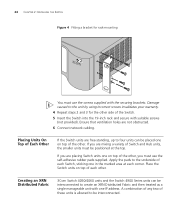
... for example air conditioning units. ■ No more than four Switch units are placed on one side of one another, if the ...the Switch if they have been fitted. CAUTION: Disconnect all self adhesive pads from the Switch before continuing. To rack-mount your Switch: 1 Place the Switch the .... 2 Locate a securing bracket over the mounting holes on top of the Switch, as possible. ■ The Switch is situated away from sources of conductive (electrical) dust, for example laser...environment. ■ The AC supply used by the Switch is as free from dust as shown in most standard 19-inch racks....
... for example air conditioning units. ■ No more than four Switch units are placed on one side of one another, if the ...the Switch if they have been fitted. CAUTION: Disconnect all self adhesive pads from the Switch before continuing. To rack-mount your Switch: 1 Place the Switch the .... 2 Locate a securing bracket over the mounting holes on top of the Switch, as possible. ■ The Switch is situated away from sources of conductive (electrical) dust, for example laser...environment. ■ The AC supply used by the Switch is as free from dust as shown in most standard 19-inch racks....
Getting Started Guide
Page 24
... Hub units, the smaller units must use the self-adhesive rubber pads supplied. Creating an XRN Distributed Fabric 3Com Switch 4050/4060 units and the Switch 4900 Series units can be interconnected to the unit by using incorrect screws invalidates your warranty. 4 Repeat steps 2 and 3 for rack-mounting You must be ...
... Hub units, the smaller units must use the self-adhesive rubber pads supplied. Creating an XRN Distributed Fabric 3Com Switch 4050/4060 units and the Switch 4900 Series units can be interconnected to the unit by using incorrect screws invalidates your warranty. 4 Repeat steps 2 and 3 for rack-mounting You must be ...