Reference Guide
Page 2
... Santa Clara, California 95052-8145 Copyright © 1998, 3Com Corporation. Technical data is a service mark of 3Com Corporation. 3ComFacts is provided with , this User Guide. 3Com, the 3Com logo, PathBuilder, and SuperStack are registered trademarks of 3Com Corporation. You agree not to remove or deface any portion...provided in DFAR 252.227-7015 (Nov 1995) or FAR 52.227-14 (June 1987), whichever is provided with which they are commercial in 3Com's standard commercial license for a particular purpose. 3Com may be provided to you in conjunction with limited rights only ...
... Santa Clara, California 95052-8145 Copyright © 1998, 3Com Corporation. Technical data is a service mark of 3Com Corporation. 3ComFacts is provided with , this User Guide. 3Com, the 3Com logo, PathBuilder, and SuperStack are registered trademarks of 3Com Corporation. You agree not to remove or deface any portion...provided in DFAR 252.227-7015 (Nov 1995) or FAR 52.227-14 (June 1987), whichever is provided with which they are commercial in 3Com's standard commercial license for a particular purpose. 3Com may be provided to you in conjunction with limited rights only ...

Reference Guide
Page 4
...the T1/E1 UNI Interface 42 Connecting to the Serial Port 42 Connecting to the Ethernet Port 51 Connecting to the OC3/STM-1 Port 52 Connecting to the CBR Module 53 Connecting to the Voice Compression Module 55 Connecting to the DS3/E3 Module 56 Step 5: Connect the ... Super User Functions 71 Taking over a Read-Write Session 71 Erasing the System Database 71 Configuring In-band Management 72 4 CONFIGURING PATHBUILDER S330/S310 MODULES, PORTS, AND A PPLICATIONS Specifying General System Information 76 Viewing RS-232 Port Configuration Information 77 Viewing the Firmware Version 77 ...
...the T1/E1 UNI Interface 42 Connecting to the Serial Port 42 Connecting to the Ethernet Port 51 Connecting to the OC3/STM-1 Port 52 Connecting to the CBR Module 53 Connecting to the Voice Compression Module 55 Connecting to the DS3/E3 Module 56 Step 5: Connect the ... Super User Functions 71 Taking over a Read-Write Session 71 Erasing the System Database 71 Configuring In-band Management 72 4 CONFIGURING PATHBUILDER S330/S310 MODULES, PORTS, AND A PPLICATIONS Specifying General System Information 76 Viewing RS-232 Port Configuration Information 77 Viewing the Firmware Version 77 ...

Reference Guide
Page 25
...+ 26 6 IN SCR- 25 13 IN SCT+ IN SCT- IN Shorting GR 1 47,48,49 Shorting GR 2 51, 52 tristate when in DTE mode) DTR OUT LL (not used ; Specifications 13 Table 4 PathBuilder S330 System Specifications Connector type at end of X.21 cable X.21 DTE cable pinouts (60-pin connector...
...+ 26 6 IN SCR- 25 13 IN SCT+ IN SCT- IN Shorting GR 1 47,48,49 Shorting GR 2 51, 52 tristate when in DTE mode) DTR OUT LL (not used ; Specifications 13 Table 4 PathBuilder S330 System Specifications Connector type at end of X.21 cable X.21 DTE cable pinouts (60-pin connector...

Reference Guide
Page 26
OUT Shorting GR 1 47,48 Shorting GR 2 51, 52 14 CHAPTER 1: SYSTEM DESCRIPTION Table 4 PathBuilder S330 System Specifications X.21 DCE cable pinouts (60-pin connector) to DB-15 female (continued) Signal Name Pin # on 60-pin Pin # on ...
OUT Shorting GR 1 47,48 Shorting GR 2 51, 52 14 CHAPTER 1: SYSTEM DESCRIPTION Table 4 PathBuilder S330 System Specifications X.21 DCE cable pinouts (60-pin connector) to DB-15 female (continued) Signal Name Pin # on 60-pin Pin # on ...

Reference Guide
Page 34
22 CHAPTER 1: SYSTEM DESCRIPTION Table 5 PathBuilder S310 System Specifications Connector type at end of EIA530 cable Connector pinouts Connector type at end of X.21 cable X.21 DTE cable pinouts (60-... SD+ 11 2 OUT SD- 12 9 OUT RD+ 28 4 IN RD- 27 11 IN SCTE+ OUT SCTE- IN Shorting GR 1 47,48,49 Shorting GR 2 51, 52 OUT SCR+ 26 6 IN SCR- 25 13 IN SCT+ IN SCT- tristate when in DTE mode) DTR OUT LL (not used ;
22 CHAPTER 1: SYSTEM DESCRIPTION Table 5 PathBuilder S310 System Specifications Connector type at end of EIA530 cable Connector pinouts Connector type at end of X.21 cable X.21 DTE cable pinouts (60-... SD+ 11 2 OUT SD- 12 9 OUT RD+ 28 4 IN RD- 27 11 IN SCTE+ OUT SCTE- IN Shorting GR 1 47,48,49 Shorting GR 2 51, 52 OUT SCR+ 26 6 IN SCR- 25 13 IN SCT+ IN SCT- tristate when in DTE mode) DTR OUT LL (not used ;

Reference Guide
Page 35
... IN LL (not used ; IN SCR+ 24 6 OUT SCR- 23 13 OUT (tristate SCR + and - OUT Shorting GR 1 47,48 Shorting GR 2 51, 52 Specifications 23 Table 5 PathBuilder S310 System Specifications X.21 DCE cable pinouts (60-pin connector) to DB-15 female (continued) Signal Name Pin # on 60-pin Pin # on...
... IN LL (not used ; IN SCR+ 24 6 OUT SCR- 23 13 OUT (tristate SCR + and - OUT Shorting GR 1 47,48 Shorting GR 2 51, 52 Specifications 23 Table 5 PathBuilder S310 System Specifications X.21 DCE cable pinouts (60-pin connector) to DB-15 female (continued) Signal Name Pin # on 60-pin Pin # on...

Reference Guide
Page 55
... Connector Connector 46 A 45 B 42 C 35 D 34 E 33 F 43 H 44 K 18 P 17 S 28 R 27 T 20 U 19 W 26 V 25 X 24 Y 23 AA 48, 49 50, 51, 52 53, 54, 55, 56 Direction (for V.35 DTE Cable (60-pin connector) to V.35 Male Signal Name Frame GND Circuit GND RTS CTS DSR DCD... Out Out Out In In Out Out In In In In Installation Procedures 43 The following tables describe the serial port connector pinouts. Note that PathBuilder S330/S310 cables are compatible with CISCO cables, except for the DCE EIA530 which CISCO does not manufacture.
... Connector Connector 46 A 45 B 42 C 35 D 34 E 33 F 43 H 44 K 18 P 17 S 28 R 27 T 20 U 19 W 26 V 25 X 24 Y 23 AA 48, 49 50, 51, 52 53, 54, 55, 56 Direction (for V.35 DTE Cable (60-pin connector) to V.35 Male Signal Name Frame GND Circuit GND RTS CTS DSR DCD... Out Out Out In In Out Out In In In In Installation Procedures 43 The following tables describe the serial port connector pinouts. Note that PathBuilder S330/S310 cables are compatible with CISCO cables, except for the DCE EIA530 which CISCO does not manufacture.

Reference Guide
Page 57
... Out 28 6 In 27 24 In 13 17 Out 14 35 Out 26 8 In 25 26 In 24 5 In 23 23 In 48, 49 51, 52,
... Out 28 6 In 27 24 In 13 17 Out 14 35 Out 26 8 In 25 26 In 24 5 In 23 23 In 48, 49 51, 52,

Reference Guide
Page 59
Installation Procedures 47 Table 15 Connector Pinouts for EIA530 DTE cable (60-pin Connector) to DB-25 Male Signal Name Frame GND Circuit GND RTS CTS DSR DCD (not used, see DCE cable) DTR LL (not used) SD+ SDRD+ RDSCTE+ SCTESCR+ SCRSCT+ SCTShorting GR 1 Shorting GR 2 Pin # on 60-pin Connector 46 45 9, 10 1, 2 3, 4 5, 6 Pin # on DB-25 Connector 1 7 4, 19 5, 13 6, 22 8, 10 Direction (for Serial Port) Out In In In 7, 8 20, 23 Out 44 18 Out 11 2 Out 12 14 Out 28 3 In 27 16 In 13 24 Out 14 11 Out 26 17 In 25 9 In 24 15 In 23 12 In 47, 48, 49 51, 52,
Installation Procedures 47 Table 15 Connector Pinouts for EIA530 DTE cable (60-pin Connector) to DB-25 Male Signal Name Frame GND Circuit GND RTS CTS DSR DCD (not used, see DCE cable) DTR LL (not used) SD+ SDRD+ RDSCTE+ SCTESCR+ SCRSCT+ SCTShorting GR 1 Shorting GR 2 Pin # on 60-pin Connector 46 45 9, 10 1, 2 3, 4 5, 6 Pin # on DB-25 Connector 1 7 4, 19 5, 13 6, 22 8, 10 Direction (for Serial Port) Out In In In 7, 8 20, 23 Out 44 18 Out 11 2 Out 12 14 Out 28 3 In 27 16 In 13 24 Out 14 11 Out 26 17 In 25 9 In 24 15 In 23 12 In 47, 48, 49 51, 52,

Reference Guide
Page 61
Installation Procedures 49 Table 17 Connector Pinouts for X.21 DTE cable (60-pin Connector) to DB-15 Male Signal Name Frame GND Circuit GND RTS CTS DSR DCD (not used, see DCE cable) DTR LL (not used) SD+ SDRD+ RDSCTE+ SCTESCR+ SCRSCT+ SCTShorting GR 1 Shorting GR 2 Pin # on 60-pin Connector 46 15 9, 10 1, 2 Pin # on DB-25 Connector 1 8 3, 10 5, 12 Direction (for Serial Port) Out In In In Out Out 11 2 Out 12 9 Out 28 4 In 27 11 In Out Out 26 6 In 25 13 In In In 47, 48 51, 52,
Installation Procedures 49 Table 17 Connector Pinouts for X.21 DTE cable (60-pin Connector) to DB-15 Male Signal Name Frame GND Circuit GND RTS CTS DSR DCD (not used, see DCE cable) DTR LL (not used) SD+ SDRD+ RDSCTE+ SCTESCR+ SCRSCT+ SCTShorting GR 1 Shorting GR 2 Pin # on 60-pin Connector 46 15 9, 10 1, 2 Pin # on DB-25 Connector 1 8 3, 10 5, 12 Direction (for Serial Port) Out In In In Out Out 11 2 Out 12 9 Out 28 4 In 27 11 In Out Out 26 6 In 25 13 In In In 47, 48 51, 52,

Reference Guide
Page 64
Figure 22 OC3/STM-1 UNI (Multi-Mode Fiber Optic Cable) Figure 23 OC3/STM-1 UNI (Single-Mode Fiber Optic Cable) Public ATM Service 52 CHAPTER 2: INSTALLATION S330 only Connecting to the OC3/STM-1 Port The OC3/STM-1 UNI port is equipped with an internal SC-type connector supporting the use of multi-mode or single-mode fiber optic cable, as shown in Figure 22 and Figure 23.
Figure 22 OC3/STM-1 UNI (Multi-Mode Fiber Optic Cable) Figure 23 OC3/STM-1 UNI (Single-Mode Fiber Optic Cable) Public ATM Service 52 CHAPTER 2: INSTALLATION S330 only Connecting to the OC3/STM-1 Port The OC3/STM-1 UNI port is equipped with an internal SC-type connector supporting the use of multi-mode or single-mode fiber optic cable, as shown in Figure 22 and Figure 23.

Reference Guide
Page 95
...sustained cell rate. How you configure the MCPU shapers depends on the type of Service) Configuring MCPU Shapers The PathBuilder S330/S310 supports three MCPU shapers parameters: n Peak Cell Rate (PCR)-The maximum rate that a bursty, on this chapter for the Shaper Number... parameter that can send; Figure 52 MCPU Configuration Menu Configuring the Management CPU 83 Viewing MCPU Configuration Information To view con...
...sustained cell rate. How you configure the MCPU shapers depends on the type of Service) Configuring MCPU Shapers The PathBuilder S330/S310 supports three MCPU shapers parameters: n Peak Cell Rate (PCR)-The maximum rate that a bursty, on this chapter for the Shaper Number... parameter that can send; Figure 52 MCPU Configuration Menu Configuring the Management CPU 83 Viewing MCPU Configuration Information To view con...

Reference Guide
Page 96
... the MCPU Card menu, shown in Figure 52, select [2] Shaper Configuration to change. The system automatically calculates the bits based on the value you want to display the MCPU Shaper screen, shown in the bits/second (bps) column. 84 CHAPTER 4: CONFIGURING PATHBUILDER S330/S310 MODULES, PORTS, AND APPLICATIONS CAUTION: When assigning...
... the MCPU Card menu, shown in Figure 52, select [2] Shaper Configuration to change. The system automatically calculates the bits based on the value you want to display the MCPU Shaper screen, shown in the bits/second (bps) column. 84 CHAPTER 4: CONFIGURING PATHBUILDER S330/S310 MODULES, PORTS, AND APPLICATIONS CAUTION: When assigning...
Reference Guide
Page 218
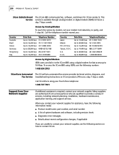
...following number: 1 408 654 2703 3ComFacts Automated The 3ComFacts automated fax service provides technical articles, diagrams, and Fax Service troubleshooting instructions on how to contact 3Com. of system hardware and software, including revision levels n Diagnostic error messages n Details about recent configuration changes, if applicable If you : ... Up to 14,400 bps Up to 14,400 bps Up to 28,800 bps Up to 28,800 bps Telephone Number 81 3 3345 7266 52 5 520 7835 86 10 684 92351 886 2 377 5840 44 1442 438278 1 408 980 8204 Access by modem, set your Touch-Tone telephone:...
...following number: 1 408 654 2703 3ComFacts Automated The 3ComFacts automated fax service provides technical articles, diagrams, and Fax Service troubleshooting instructions on how to contact 3Com. of system hardware and software, including revision levels n Diagnostic error messages n Details about recent configuration changes, if applicable If you : ... Up to 14,400 bps Up to 14,400 bps Up to 28,800 bps Up to 28,800 bps Telephone Number 81 3 3345 7266 52 5 520 7835 86 10 684 92351 886 2 377 5840 44 1442 438278 1 408 980 8204 Access by modem, set your Touch-Tone telephone:...

Reference Guide
Page 256
... rate 91 Default Gateway Configuration menu 68 default gateway, configuring 68 Designated Bridge ID 196 dest phone # 163 Destination Address Filter menu 118 destination address filtering 118 DFA... mode 219 framing 91, 124, 132 FR-SSCS DLCI 153 full system configuration PathBuilder 310 32 PathBuilder 330 31 G gain limit 91 General System Information menu 76, 77 getting started 59 group...40 management terminal 57, 58, 59 OC3/STM-1 port 52 OC3/STM-1 port (multi-mode fiber) 52 OC3/STM-1 port (single-mode fiber) 52 port 41 serial port 42 T1/E1 UNI interface 42 ...
... rate 91 Default Gateway Configuration menu 68 default gateway, configuring 68 Designated Bridge ID 196 dest phone # 163 Destination Address Filter menu 118 destination address filtering 118 DFA... mode 219 framing 91, 124, 132 FR-SSCS DLCI 153 full system configuration PathBuilder 310 32 PathBuilder 330 31 G gain limit 91 General System Information menu 76, 77 getting started 59 group...40 management terminal 57, 58, 59 OC3/STM-1 port 52 OC3/STM-1 port (multi-mode fiber) 52 OC3/STM-1 port (single-mode fiber) 52 port 41 serial port 42 T1/E1 UNI interface 42 ...

Reference Guide
Page 257
...E1 UNI interface 180 LOS 56 M M Factor See Multiplex (M) Factor MAC address 119 MAC MTU Exceeded 195 Main menu 60 options 61 Manage Bridge menu 113 Manage IP Network Configuration menu 65 Manage Video Dial menu 160 Management 57, 209 management CPU 151, 209 alarms 81 con...list 27 passwords changing default 63, 70 default 60 setting 69 PathBuilder 27 Pathbuilder 330 features 5 of IMA group(s) 103 O OC3/STM-1 port 213 configuring 104 connecting 52 connecting (multi-mode fiber) 52 connecting (single-mode fiber) 52 data flow 213 LEDs 53 loopbacks 181 principles of ...
...E1 UNI interface 180 LOS 56 M M Factor See Multiplex (M) Factor MAC address 119 MAC MTU Exceeded 195 Main menu 60 options 61 Manage Bridge menu 113 Manage IP Network Configuration menu 65 Manage Video Dial menu 160 Management 57, 209 management CPU 151, 209 alarms 81 con...list 27 passwords changing default 63, 70 default 60 setting 69 PathBuilder 27 Pathbuilder 330 features 5 of IMA group(s) 103 O OC3/STM-1 port 213 configuring 104 connecting 52 connecting (multi-mode fiber) 52 connecting (single-mode fiber) 52 data flow 213 LEDs 53 loopbacks 181 principles of ...