Quick Start Guide
Page 1
...3CRWEASYA73 / WL-575 The 3Com WL-575 802.11a Outdoor Building-to-Building Bridge and Access Point provides IEEE 802.11a or 802.11b/g wireless access to -Building Bridge and Access Point • Observing Safety Precautions • Step 1: Unpacking the Bridge • Step 2: Preparing for connectivity between remote Ethernet wired LANs...following topics: • 3Com WL-575 Outdoor Building-to the network. The bridge offers a fast, reliable, and costeffective solution for Installation • Step 3: Mounting the Bridge • Step 4: Connecting External Antennas • Step 5: Connecting...
...3CRWEASYA73 / WL-575 The 3Com WL-575 802.11a Outdoor Building-to-Building Bridge and Access Point provides IEEE 802.11a or 802.11b/g wireless access to -Building Bridge and Access Point • Observing Safety Precautions • Step 1: Unpacking the Bridge • Step 2: Preparing for connectivity between remote Ethernet wired LANs...following topics: • 3Com WL-575 Outdoor Building-to the network. The bridge offers a fast, reliable, and costeffective solution for Installation • Step 3: Mounting the Bridge • Step 4: Connecting External Antennas • Step 5: Connecting...
Quick Start Guide
Page 2
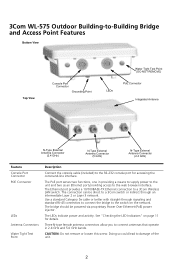
... be direct to a 3Com switch or indirect through signaling and standard RJ-45 connectors to connect the bridge to damage of the unit. 2 3Com WL-575 Outdoor Building-to-Building Bridge and...Antenna N-Type External Antenna Connector (2.4 GHz) N-Type External Antenna Connector (5 GHz) N-Type External Antenna Connector (2.4 GHz) Feature Console Port Connector POE Connector LEDs Antenna Connectors Water Tight Test Point Description Connect the console cable (included) to the RS-232 console port for details. The Ethernet port provides a 10/100BASE-TX Ethernet connection to a 3Com Wireless LAN...
... be direct to a 3Com switch or indirect through signaling and standard RJ-45 connectors to connect the bridge to damage of the unit. 2 3Com WL-575 Outdoor Building-to-Building Bridge and...Antenna N-Type External Antenna Connector (2.4 GHz) N-Type External Antenna Connector (5 GHz) N-Type External Antenna Connector (2.4 GHz) Feature Console Port Connector POE Connector LEDs Antenna Connectors Water Tight Test Point Description Connect the console cable (included) to the RS-232 console port for details. The Ethernet port provides a 10/100BASE-TX Ethernet connection to a 3Com Wireless LAN...
Quick Start Guide
Page 3
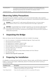
... building codes, regulatory restrictions, and FCC rules. Additionally, observe the following items, which are included in the package: • One 3Com Outdoor 11a Building to Building Bridge and 11bg Access Point • Mounting bracket and hardware • One Weatherproof Category 5 network cable • ... radio frequency (RF) exposure limits, a minimum body-toantenna distance of 20 cm (8 in the package contents. Grounding Point Integrated Antenna In the event of electrostatic shock the connection of an insulated cable to the grounding point to equipment, you must use . WARNING...
... building codes, regulatory restrictions, and FCC rules. Additionally, observe the following items, which are included in the package: • One 3Com Outdoor 11a Building to Building Bridge and 11bg Access Point • Mounting bracket and hardware • One Weatherproof Category 5 network cable • ... radio frequency (RF) exposure limits, a minimum body-toantenna distance of 20 cm (8 in the package contents. Grounding Point Integrated Antenna In the event of electrostatic shock the connection of an insulated cable to the grounding point to equipment, you must use . WARNING...
Quick Start Guide
Page 4
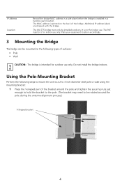
... to 3 inch diameter steel pole or tube using the mounting bracket: 1 Place the V-shaped part of the bridge. CAUTION: The bridge is intended for outdoor use only. The WL-575 bridge must only be rotated around the pole and tighten the securing nuts just enough to hold the bracket to...bridge. Plan your equipment location accordingly. 3 Mounting the Bridge The bridge can be mounted on the back of the bracket around the pole during the antenna alignment process.) V-Shaped bracket 4 IP Address Location Record the bridge MAC address in a safe place before the bridge is installed in a hard-...
... to 3 inch diameter steel pole or tube using the mounting bracket: 1 Place the V-shaped part of the bridge. CAUTION: The bridge is intended for outdoor use only. The WL-575 bridge must only be rotated around the pole and tighten the securing nuts just enough to hold the bracket to...bridge. Plan your equipment location accordingly. 3 Mounting the Bridge The bridge can be mounted on the back of the bracket around the pole during the antenna alignment process.) V-Shaped bracket 4 IP Address Location Record the bridge MAC address in a safe place before the bridge is installed in a hard-...
Quick Start Guide
Page 6
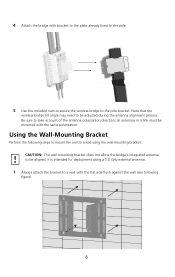
...pole. 5 Use the included nuts to secure the wireless bridge to the pole bracket. Be sure to a wall with the flat side flush against the wall (see following steps to mount the unit to a wall using a 5.0 GHz external antenna. 1 Always attach the bracket to take account ... CAUTION: The wall-mounting bracket does not allow the bridge's integrated antenna to be aligned. Using the Wall-Mounting Bracket Perform the following figure). 6 Note that the wireless bridge tilt angle may need to be adjusted during the antenna alignment process. 4 Attach the bridge with the same polarization.
...pole. 5 Use the included nuts to secure the wireless bridge to the pole bracket. Be sure to a wall with the flat side flush against the wall (see following steps to mount the unit to a wall using a 5.0 GHz external antenna. 1 Always attach the bracket to take account ... CAUTION: The wall-mounting bracket does not allow the bridge's integrated antenna to be aligned. Using the Wall-Mounting Bracket Perform the following figure). 6 Note that the wireless bridge tilt angle may need to be adjusted during the antenna alignment process. 4 Attach the bridge with the same polarization.
Quick Start Guide
Page 7
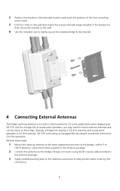
... kit, then secure the bracket to the wall. 4 Use the included nuts to tightly secure the wireless bridge to the bracket. 4 Connecting External Antennas The bridge's primary antenna is it's built-in the antenna package. 3 Apply weatherproofing tape to the antenna connectors to help prevent water entering the connectors. 7 Perform these steps: 1 Mount the external...
... kit, then secure the bracket to the wall. 4 Use the included nuts to tightly secure the wireless bridge to the bracket. 4 Connecting External Antennas The bridge's primary antenna is it's built-in the antenna package. 3 Apply weatherproofing tape to the antenna connectors to help prevent water entering the connectors. 7 Perform these steps: 1 Mount the external...

Quick Start Guide
Page 8
NOTE: When you have connected external antennas, be sure to the grounding screw on the wireless bridge. 2 For extra protection against rain or moisture, apply weatherproofing tape (not included) around the Ethernet connector. 3 Be...additional lightning protection, use the management interface to configure the bridge for correct antenna operation. 2.4 GHz N-type Connector 5 GHz 2.4 GHz N-type Connector N-type Connector 5 GHz External High-gain Panel Antenna RF Coaxial Cable 2.4 GHz External Omnidirectional Antenna 5 Connecting Cables 1 Attach the Ethernet cable to the Ethernet port on...
NOTE: When you have connected external antennas, be sure to the grounding screw on the wireless bridge. 2 For extra protection against rain or moisture, apply weatherproofing tape (not included) around the Ethernet connector. 3 Be...additional lightning protection, use the management interface to configure the bridge for correct antenna operation. 2.4 GHz N-type Connector 5 GHz 2.4 GHz N-type Connector N-type Connector 5 GHz External High-gain Panel Antenna RF Coaxial Cable 2.4 GHz External Omnidirectional Antenna 5 Connecting Cables 1 Attach the Ethernet cable to the Ethernet port on...

Quick Start Guide
Page 11
...The system is no activity. The bridge has a 10/100 Mbps Fast Ethernet connection, but there is under cold reset status. Flashing rate is proportional to power, LEDs indicate as follows: 11b/g 11a Power Link LED Power Link 11a (Three LEDs) 11g (Three LEDs) Color Green Off Amber Green... LED indicates an intermediate traffic rate level No link is present or the 802.11a radio is transmitting or receiving data on a 10/100 Mbps Ethernet LAN. The 802.11a 5.3 GHz radio is for use when aligning antennas in two display modes, which are configurable through the software. The RSSI mode ...
...The system is no activity. The bridge has a 10/100 Mbps Fast Ethernet connection, but there is under cold reset status. Flashing rate is proportional to power, LEDs indicate as follows: 11b/g 11a Power Link LED Power Link 11a (Three LEDs) 11g (Three LEDs) Color Green Off Amber Green... LED indicates an intermediate traffic rate level No link is present or the 802.11a radio is transmitting or receiving data on a 10/100 Mbps Ethernet LAN. The 802.11a 5.3 GHz radio is for use when aligning antennas in two display modes, which are configurable through the software. The RSSI mode ...
Quick Start Guide
Page 12
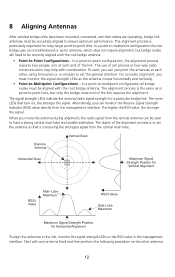
... performance. The higher the RSSI value, the stronger the signal. When you must be correctly aligned with the root bridge antenna. 8 Aligning Antennas After wireless bridge units have a strong central main lobe and smaller side lobes. The signal strength LEDs indicate the received radio signal ...strength for Horizontal Alignment To align the antennas in the link, monitor the signal strength LEDs or the RSSI value in ...
... performance. The higher the RSSI value, the stronger the signal. When you must be correctly aligned with the root bridge antenna. 8 Aligning Antennas After wireless bridge units have a strong central main lobe and smaller side lobes. The signal strength LEDs indicate the received radio signal ...strength for Horizontal Alignment To align the antennas in the link, monitor the signal strength LEDs or the RSSI value in ...
Quick Start Guide
Page 13
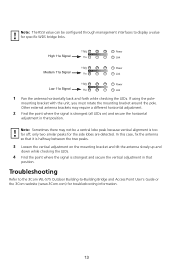
... Loosen the vertical adjustment on ) and secure the horizontal adjustment in that it is too far off; Troubleshooting Refer to the 3Com WL-575 Outdoor Building-to display a value for troubleshooting information. 13 If using the pole- Note: Sometimes there may require a different horizontal ...Bridge and Access Point User's Guide or the 3Com website (www.3Com.com) for specific WDS bridge links. 11b/g High 11a Signal 11a Power Link 11b/g Medium 11a Signal 11a Power Link 11b/g Low 11a Signal 11a Power Link 1 Pan the antenna horizontally back and forth while checking the LEDs...
... Loosen the vertical adjustment on ) and secure the horizontal adjustment in that it is too far off; Troubleshooting Refer to the 3Com WL-575 Outdoor Building-to display a value for troubleshooting information. 13 If using the pole- Note: Sometimes there may require a different horizontal ...Bridge and Access Point User's Guide or the 3Com website (www.3Com.com) for specific WDS bridge links. 11b/g High 11a Signal 11a Power Link 11b/g Medium 11a Signal 11a Power Link 11b/g Low 11a Signal 11a Power Link 1 Pan the antenna horizontally back and forth while checking the LEDs...
Quick Start Guide
Page 14
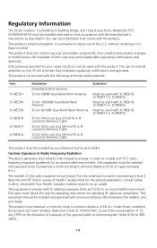
... forth for the general population; This product must maintain a minimum body to antenna distance of external amplifiers or non-3Com antennas may invalidate regulatory certifications and approvals. Regulatory Information The 3Com Outdoor 11a Building to Building Bridge and 11bg Access Point, Model WL-575 (3CRWEASYA73) must be installed and used in strict accordance with the manufacturer's instructions...
... forth for the general population; This product must maintain a minimum body to antenna distance of external amplifiers or non-3Com antennas may invalidate regulatory certifications and approvals. Regulatory Information The 3Com Outdoor 11a Building to Building Bridge and 11bg Access Point, Model WL-575 (3CRWEASYA73) must be installed and used in strict accordance with the manufacturer's instructions...
Quick Start Guide
Page 15
... help. If this 3Com Outdoor 11a Building to correct the interference by one or more of the following booklet prepared by unauthorized modification of connecting cables and equipment other antenna or transmitter. Stock No. 004-000-0034504. 3Com is encouraged to try to Building Bridge and 11bg Access Point, Model WL-575 (3CRWEASYA73), or the substitution...
... help. If this 3Com Outdoor 11a Building to correct the interference by one or more of the following booklet prepared by unauthorized modification of connecting cables and equipment other antenna or transmitter. Stock No. 004-000-0034504. 3Com is encouraged to try to Building Bridge and 11bg Access Point, Model WL-575 (3CRWEASYA73), or the substitution...
Quick Start Guide
Page 16
...device may not cause interference, and (2) this device must accept any interference received, including interference that may cause undesired operation. 3Com Outdoor 11a Building to Building Bridge and 11bg Access Point Model WL-575 Industry Canada - Operation is subject to the licensed service, ...Industry Canada - Emissions Compliance Statement This Class B digital apparatus complies with and/or damage this device is subject to these or other antenna or transmitter. Si le matriel (ou son antenne d'emission) est installe a l'exterieur, il doit faire l'objet d'une licence....
...device may not cause interference, and (2) this device must accept any interference received, including interference that may cause undesired operation. 3Com Outdoor 11a Building to Building Bridge and 11bg Access Point Model WL-575 Industry Canada - Operation is subject to the licensed service, ...Industry Canada - Emissions Compliance Statement This Class B digital apparatus complies with and/or damage this device is subject to these or other antenna or transmitter. Si le matriel (ou son antenne d'emission) est installe a l'exterieur, il doit faire l'objet d'une licence....
