
User Manual
Page 3
Contents 1 Introduction 5 1.1 Package Contents 5 1.2 Specifications 6 1.3 Motherboard Layout 8 1.4 ASRock 8CH I/O 9 2 Installation 10 2.1 Screw Holes 10 2.2 Pre-installation Precautions 10 2.3 CPU Installation 11 2.4 Installation of Heatsink ...Surround Display Feature 16 2.8 Jumpers Setup 16 2.9 Onboard Headers and Connectors 17 2.10 Serial ATA (SATA) Hard Disks Installation 20 3 BIOS SETUP UTILITY 21 3.1 Introduction 23 3.1.1 BIOS Menu Bar 23 3.1.2 Navigation Keys 22 3.2 Main Screen 22 3.3 Advanced Screen 22 3.3.1 CPU Configuration 23 3.3.2 Chipset Configuration 24 3.3.3 ...
Contents 1 Introduction 5 1.1 Package Contents 5 1.2 Specifications 6 1.3 Motherboard Layout 8 1.4 ASRock 8CH I/O 9 2 Installation 10 2.1 Screw Holes 10 2.2 Pre-installation Precautions 10 2.3 CPU Installation 11 2.4 Installation of Heatsink ...Surround Display Feature 16 2.8 Jumpers Setup 16 2.9 Onboard Headers and Connectors 17 2.10 Serial ATA (SATA) Hard Disks Installation 20 3 BIOS SETUP UTILITY 21 3.1 Introduction 23 3.1.1 BIOS Menu Bar 23 3.1.2 Navigation Keys 22 3.2 Main Screen 22 3.3 Advanced Screen 22 3.3.1 CPU Configuration 23 3.3.2 Chipset Configuration 24 3.3.3 ...

User Manual
Page 5
... Installation Live Demo) One 80-conductor Ultra ATA 66/100 IDE Ribbon Cable One Ribbon Cable for purchasing ASRock 775i915PL-M motherboard, a reliable motherboard produced under ASRock's consistently stringent quality control. Because the motherboard specifications and the BIOS software might be updated, the content of this manual will be subject to quality and endurance. In...
... Installation Live Demo) One 80-conductor Ultra ATA 66/100 IDE Ribbon Cable One Ribbon Cable for purchasing ASRock 775i915PL-M motherboard, a reliable motherboard produced under ASRock's consistently stringent quality control. Because the motherboard specifications and the BIOS software might be updated, the content of this manual will be subject to quality and endurance. In...

User Manual
Page 7
... system will appear in "Display Adapters" of the display adapter controllers, and then you implement Dual Channel Memory Technology, make sure to perform over-clocking. BIOS: OS: Audio Jack: Side Speaker / Rear Speaker / Central/Bass / Line In / Front Speaker / Microphone (see CAUTION 5) AMI legal...
... system will appear in "Display Adapters" of the display adapter controllers, and then you implement Dual Channel Memory Technology, make sure to perform over-clocking. BIOS: OS: Audio Jack: Side Speaker / Rear Speaker / Central/Bass / Line In / Front Speaker / Microphone (see CAUTION 5) AMI legal...

User Manual
Page 8
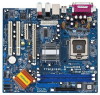
... PCI 1 PCI 2 USB2.0 IntIeClH6 CMOS Battery SPEAKER1 1 USB45 USB67 1 1 CLRCMOS1 1 USB45 PANEL1 PLED PWRBTN 1 HDLED RESET SATA1 SATA2 SATA3 SATA4 775i915PL-M PCI EXPRESS 24.4cm (9.6 in) 8 9 10 11 12 13 22 21 20 19 18 17 161514 1 PS2_USB_PWR1 Jumper 2 ATX 12V Connector (ATX12V1... North Bridge Controller 5 CPU Fan Connector (CPU_FAN1) 6 184-pin DDR DIMM Slots (DDR1- 2, Dual Channel) 7 Infrared Module Connector (IR1) 8 BIOS FWH Chip 9 Floppy Connector (FLOPPY1) 10 Chassis Fan Connector (CHA_FAN1) 11 Primary IDE Connector (IDE1, Black) 12 South Bridge Controller 13 Chassis Speaker ...
... PCI 1 PCI 2 USB2.0 IntIeClH6 CMOS Battery SPEAKER1 1 USB45 USB67 1 1 CLRCMOS1 1 USB45 PANEL1 PLED PWRBTN 1 HDLED RESET SATA1 SATA2 SATA3 SATA4 775i915PL-M PCI EXPRESS 24.4cm (9.6 in) 8 9 10 11 12 13 22 21 20 19 18 17 161514 1 PS2_USB_PWR1 Jumper 2 ATX 12V Connector (ATX12V1... North Bridge Controller 5 CPU Fan Connector (CPU_FAN1) 6 184-pin DDR DIMM Slots (DDR1- 2, Dual Channel) 7 Infrared Module Connector (IR1) 8 BIOS FWH Chip 9 Floppy Connector (FLOPPY1) 10 Chassis Fan Connector (CHA_FAN1) 11 Primary IDE Connector (IDE1, Black) 12 South Bridge Controller 13 Chassis Speaker ...

User Manual
Page 16
With the external add-on PCI Express VGA card, you update the BIOS. The illustration shows a 3-pin jumper whose pin1 and pin2 are short, both the front panel and the rear panel audio connectors can easily enjoy the ... CD: ..\ Surround Display 2.8 Jumpers Setup The illustration shows how jumpers are setup. If you need to clear the CMOS when you just finish updating the BIOS, you must boot up events. After waiting for PS/2 +5V +5VSB or USB wake up the system first, and then shut it requires 2 Amp and...
With the external add-on PCI Express VGA card, you update the BIOS. The illustration shows a 3-pin jumper whose pin1 and pin2 are short, both the front panel and the rear panel audio connectors can easily enjoy the ... CD: ..\ Surround Display 2.8 Jumpers Setup The illustration shows how jumpers are setup. If you need to clear the CMOS when you just finish updating the BIOS, you must boot up events. After waiting for PS/2 +5V +5VSB or USB wake up the system first, and then shut it requires 2 Amp and...

User Manual
Page 21
... of the screen has a menu bar with its test routines. If you start up the security features Exit To exit the current screen or the BIOS SETUP UTILITY Use < > key or < > key to choose among the selections on the menu bar, and then press to get into the sub screen. 21... UTILITY, otherwise, POST will continue with the following selections: Main To set up the system time/date information Advanced To set up the advanced BIOS features H/W Monitor To display current hardware status Boot To set up the default system device to locate and load the Operating System Security To set ...
... of the screen has a menu bar with its test routines. If you start up the security features Exit To exit the current screen or the BIOS SETUP UTILITY Use < > key or < > key to choose among the selections on the menu bar, and then press to get into the sub screen. 21... UTILITY, otherwise, POST will continue with the following selections: Main To set up the system time/date information Advanced To set up the advanced BIOS features H/W Monitor To display current hardware status Boot To set up the default system device to locate and load the Operating System Security To set ...

User Manual
Page 22
... UTILITY Main Advanced H/W Monitor Boot Security Exit System Overview System Time System Date [14:00:09] [Thu 05/05/2005] BIOS Version : 775i915PL-M BIOS P1.00 Processor Type : Intel (R) CPU 3.60 GHz Processor Speed : 3600 MHz Microcode Update : F43/04 Cache Size : 2048KB Total ... screen 3.2 Main Screen When you may set the configurations for the following table for all the settings To save changes and exit the BIOS SETUP UTILITY To jump to select a field. 3.1.2 Navigation Keys Please check the following items: CPU Configuration, Chipset Configuration, ACPI Configuration,...
... UTILITY Main Advanced H/W Monitor Boot Security Exit System Overview System Time System Date [14:00:09] [Thu 05/05/2005] BIOS Version : 775i915PL-M BIOS P1.00 Processor Type : Intel (R) CPU 3.60 GHz Processor Speed : 3600 MHz Microcode Update : F43/04 Cache Size : 2048KB Total ... screen 3.2 Main Screen When you may set the configurations for the following table for all the settings To save changes and exit the BIOS SETUP UTILITY To jump to select a field. 3.1.2 Navigation Keys Please check the following items: CPU Configuration, Chipset Configuration, ACPI Configuration,...

User Manual
Page 23
...Boot Security Exit Advanced Settings WARNING : Setting wrong values in below sections may cause the system to malfunction. 3.3.1 CPU Configuration BIOS SETUP UTILITY Advanced CPU Configuration CPU Host Frequency Actual Frequency (MHz) Boot Failure Guard Spread Spectrum Ratio Status Ratio Actual Value CPU... SuperIO Configuration USB Configuration Configure CPU Select Screen Select Item Enter Go to malfunction. CPU Host Frequency While entering setup, BIOS auto detects the present CPU host frequency of Boot Failure Guard. Boot Failure Guard Enable or disable the feature of this...
...Boot Security Exit Advanced Settings WARNING : Setting wrong values in below sections may cause the system to malfunction. 3.3.1 CPU Configuration BIOS SETUP UTILITY Advanced CPU Configuration CPU Host Frequency Actual Frequency (MHz) Boot Failure Guard Spread Spectrum Ratio Status Ratio Actual Value CPU... SuperIO Configuration USB Configuration Configure CPU Select Screen Select Item Enter Go to malfunction. CPU Host Frequency While entering setup, BIOS auto detects the present CPU host frequency of Boot Failure Guard. Boot Failure Guard Enable or disable the feature of this...

User Manual
Page 25
3.3.2 Chipset Configuration BIOS SETUP UTILITY Advanced Chipset Configuration DRAM Frequency [Auto] Flexibility Option [Disabled] Configure DRAM Timing by SPD Select [Enabled] will find the items "DRAM RAS# Precharge", ...
3.3.2 Chipset Configuration BIOS SETUP UTILITY Advanced Chipset Configuration DRAM Frequency [Auto] Flexibility Option [Disabled] Configure DRAM Timing by SPD Select [Enabled] will find the items "DRAM RAS# Precharge", ...

User Manual
Page 26
... mode. OnBoard LAN This allows you to turn on AC/Power Loss This allows you to select VCCM. The default value is [Low]. 3.3.3 ACPI Configuration BIOS SETUP UTILITY Advanced ACPI Configuration Suspend To RAM Restore on the system from the power-soft-off when the power recovers. Configuration options: [High], [Low...
... mode. OnBoard LAN This allows you to turn on AC/Power Loss This allows you to select VCCM. The default value is [Low]. 3.3.3 ACPI Configuration BIOS SETUP UTILITY Advanced ACPI Configuration Suspend To RAM Restore on the system from the power-soft-off when the power recovers. Configuration options: [High], [Low...

User Manual
Page 27
... will not work. PS/2 Keyboard Power On Use this item to enable or disable RTC (Real Time Clock) to turn on the system. 3.3.4 IDE Configuration BIOS SETUP UTILITY Advanced IDE Configuration ATA/IDE Configuration SATA1 SATA2 SATA3 SATA4 IDE1 Master IDE1 Slave [Enhanced] [Hard Disk] [Not Detected] [Not Detected] [Not Detected...
... will not work. PS/2 Keyboard Power On Use this item to enable or disable RTC (Real Time Clock) to turn on the system. 3.3.4 IDE Configuration BIOS SETUP UTILITY Advanced IDE Configuration ATA/IDE Configuration SATA1 SATA2 SATA3 SATA4 IDE1 Master IDE1 Slave [Enhanced] [Hard Disk] [Not Detected] [Not Detected] [Not Detected...

User Manual
Page 28
.... 28 for the device that you specify. TYPE Use this item to automatically detect the hard disk drive. After selecting the hard disk information into BIOS, use a disk utility, such as MO. Make sure to set the IDE configuration for Netware and UNIX user, select [Disabled] to the system. +F1 F9...] [Enabled] Select the type of IDE device. [Auto]: Select [Auto] to select the LBA/Large mode for a hard disk > 512 MB under DOS and Windows; BIOS SETUP UTILITY Advanced Primary IDE Master Device Vendor Size LBA Mode Block Mode PIO Mode Async DMA Ultra DMA S.M.A.R.T.
.... 28 for the device that you specify. TYPE Use this item to automatically detect the hard disk drive. After selecting the hard disk information into BIOS, use a disk utility, such as MO. Make sure to set the IDE configuration for Netware and UNIX user, select [Disabled] to the system. +F1 F9...] [Enabled] Select the type of IDE device. [Auto]: Select [Auto] to select the LBA/Large mode for a hard disk > 512 MB under DOS and Windows; BIOS SETUP UTILITY Advanced Primary IDE Master Device Vendor Size LBA Mode Block Mode PIO Mode Async DMA Ultra DMA S.M.A.R.T.

User Manual
Page 29
...], [Auto], [Enabled]. 32-Bit Data Transfer Use this item to enable 32-bit access to maximize the IDE hard disk data transfer rate. 3.3.5 PCIPnP Configuration BIOS SETUP UTILITY Advanced PCI / PnP Configuration WARNING: Setting wrong values in units of this item is enabled, it will enhance hard disk performance by optimizing...
...], [Auto], [Enabled]. 32-Bit Data Transfer Use this item to enable 32-bit access to maximize the IDE hard disk data transfer rate. 3.3.5 PCIPnP Configuration BIOS SETUP UTILITY Advanced PCI / PnP Configuration WARNING: Setting wrong values in units of this item is enabled, it will enhance hard disk performance by optimizing...

User Manual
Page 30
...Option General Help Load Defaults Save and Exit Exit v02.54 (C) Copyright 1985-2005, American Megatrends, Inc. 3.3.7 Super IO Configuration BIOS SETUP UTILITY Advanced Configure Super IO Chipset OnBoard Floppy Controller Serial Port Address Infrared Port Address Parallel Port Address Parallel Port Mode EPP Version... ECP Mode DMA Channel Parallel Port IRQ [Enabled] [3F8 / IRQ4] [Disabled] [378] [ECP + EPP] [1.9] [DMA3] [IRQ7] Allow BIOS to Enable or Disable Floppy Controller. +F1 F9 F10 ESC Select Screen Select Item Change Option General Help Load Defaults Save and Exit Exit v02...
...Option General Help Load Defaults Save and Exit Exit v02.54 (C) Copyright 1985-2005, American Megatrends, Inc. 3.3.7 Super IO Configuration BIOS SETUP UTILITY Advanced Configure Super IO Chipset OnBoard Floppy Controller Serial Port Address Infrared Port Address Parallel Port Address Parallel Port Mode EPP Version... ECP Mode DMA Channel Parallel Port IRQ [Enabled] [3F8 / IRQ4] [Disabled] [378] [ECP + EPP] [1.9] [DMA3] [IRQ7] Allow BIOS to Enable or Disable Floppy Controller. +F1 F9 F10 ESC Select Screen Select Item Change Option General Help Load Defaults Save and Exit Exit v02...

User Manual
Page 32
3.3.8 USB Configuration BIOS SETUP UTILITY Advanced USB Configuration USB Controller USB 2.0 Support Legacy USB Support [Enabled] [Enabled] [Disabled] To enable or disable the onboard USB controllers. +F1 F9 ... Select Item General Help Load Defaults Save and Exit Exit v02.54 (C) Copyright 1985-2005, American Megatrends, Inc. 32 etc. Or you to auto-detect; BIOS SETUP UTILITY Main Advanced H/W Monitor Boot Security Exit Hardware Health Event Monitoring CPU Temperature M / B Temperature CPU Fan Speed Chassis Fan Speed Vcore + 3.30V + 5.00V + 12...
3.3.8 USB Configuration BIOS SETUP UTILITY Advanced USB Configuration USB Controller USB 2.0 Support Legacy USB Support [Enabled] [Enabled] [Disabled] To enable or disable the onboard USB controllers. +F1 F9 ... Select Item General Help Load Defaults Save and Exit Exit v02.54 (C) Copyright 1985-2005, American Megatrends, Inc. 32 etc. Or you to auto-detect; BIOS SETUP UTILITY Main Advanced H/W Monitor Boot Security Exit Hardware Health Event Monitoring CPU Temperature M / B Temperature CPU Fan Speed Chassis Fan Speed Vcore + 3.30V + 5.00V + 12...

User Manual
Page 33
... Go to identify the temperature of 90% or 85%. 3.5 Boot Screen In this option to configure the boot settings and the boot priority. Main Advanced BIOS SETUP UTILITY H/W Monitor Boot Security Exit Boot Settings Boot Settings Configuration Configure Settings during System Boot. 1st Boot Device 2nd Boot Device 3rd Boot Device...
... Go to identify the temperature of 90% or 85%. 3.5 Boot Screen In this option to configure the boot settings and the boot priority. Main Advanced BIOS SETUP UTILITY H/W Monitor Boot Security Exit Boot Settings Boot Settings Configuration Configure Settings during System Boot. 1st Boot Device 2nd Boot Device 3rd Boot Device...

User Manual
Page 34
...Numeric Lock function after boot-up. 3.6 Security Screen In this item is set to enable or disable the Boot From Network feature. BIOS SETUP UTILITY Main Advanced H/W Monitor Boot Security Exit Security Settings Supervisor Password : Not Installed User Password : Not Installed Change Supervisor ...or change the supervisor/user password for the system. Boot From Network Use this item to [On], it . 3.5.1 Boot Settings Configuration BIOS SETUP UTILITY Boot Boot Settings Configuration Boot From Network Bootup Num-Lock [Disabled] [On] To enable or disable the boot from network ...
...Numeric Lock function after boot-up. 3.6 Security Screen In this item is set to enable or disable the Boot From Network feature. BIOS SETUP UTILITY Main Advanced H/W Monitor Boot Security Exit Security Settings Supervisor Password : Not Installed User Password : Not Installed Change Supervisor ...or change the supervisor/user password for the system. Boot From Network Use this item to [On], it . 3.5.1 Boot Settings Configuration BIOS SETUP UTILITY Boot Boot Settings Configuration Boot From Network Bootup Num-Lock [Disabled] [On] To enable or disable the boot from network ...

User Manual
Page 35
... Defaults When you select this option, it will pop-out the following message, "Load optimal defaults?" Select [OK] to exit the BIOS SETUP UTILITY without saving any changes. F10 key can be used for all changes. Save Changes and Exit When you select this option,...will pop-out the following message, "Discard changes and exit setup?" Discard Changes When you select this operation. 3.7 Exit Screen Main BIOS SETUP UTILITY Advanced H/W Monitro Boot Security Exit Exit Options Save Changes and Exit Discard Changes and Exit Discard Changes Load Optimal Defaults Exit...
... Defaults When you select this option, it will pop-out the following message, "Load optimal defaults?" Select [OK] to exit the BIOS SETUP UTILITY without saving any changes. F10 key can be used for all changes. Save Changes and Exit When you select this option,...will pop-out the following message, "Discard changes and exit setup?" Discard Changes When you select this operation. 3.7 Exit Screen Main BIOS SETUP UTILITY Advanced H/W Monitro Boot Security Exit Exit Options Save Changes and Exit Discard Changes and Exit Discard Changes Load Optimal Defaults Exit...


