
User Manual
Page 2
...corporate names appearing in this manual may or may apply, see www.dtsc.ca.gov/hazardouswaste/perchlorate" ASRock Website: http://www.asrock.com 2 ASRock assumes no event shall ASRock, its directors, officers, employees, or agents be liable for any indirect, special, incidental, or ...may cause undesired operation. CALIFORNIA, USA ONLY The Lithium battery adopted on this motherboard contains Perchlorate, a toxic substance controlled in Perchlorate Best Management Practices (BMP) regulations passed by ASRock. Operation is subject to the implied warranties or conditions of the FCC Rules...
...corporate names appearing in this manual may or may apply, see www.dtsc.ca.gov/hazardouswaste/perchlorate" ASRock Website: http://www.asrock.com 2 ASRock assumes no event shall ASRock, its directors, officers, employees, or agents be liable for any indirect, special, incidental, or ...may cause undesired operation. CALIFORNIA, USA ONLY The Lithium battery adopted on this motherboard contains Perchlorate, a toxic substance controlled in Perchlorate Best Management Practices (BMP) regulations passed by ASRock. Operation is subject to the implied warranties or conditions of the FCC Rules...

User Manual
Page 3
... 45 2.17.2 Installing Windows® 7 / 7 64-bit / VistaTM / VistaTM 64-bit Without RAID Functions 46 2.18 Untied Overclocking Technology 46 3 Contents 1 . Introduction 5 1.1 Package Contents 5 1.2 Specifications 6 1.3 Motherboard Layout 12 1.4 I/O Panel 13 2 .
... 45 2.17.2 Installing Windows® 7 / 7 64-bit / VistaTM / VistaTM 64-bit Without RAID Functions 46 2.18 Untied Overclocking Technology 46 3 Contents 1 . Introduction 5 1.1 Package Contents 5 1.2 Specifications 6 1.3 Motherboard Layout 12 1.4 I/O Panel 13 2 .
User Manual
Page 5
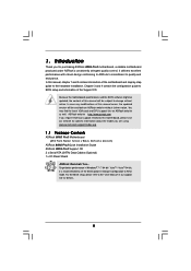
..., the content of this manual, chapter 1 and 2 contain introduction of the motherboard and step-by-step guide to BIOS setup and information of this motherboard, please visit our website for purchasing ASRock 880G Pro3 motherboard, a reliable motherboard produced under ASRock's consistently stringent quality control. ASRock website http://www.asrock.com If you are using. 1. In case any modifications of the...
..., the content of this manual, chapter 1 and 2 contain introduction of the motherboard and step-by-step guide to BIOS setup and information of this motherboard, please visit our website for purchasing ASRock 880G Pro3 motherboard, a reliable motherboard produced under ASRock's consistently stringent quality control. ASRock website http://www.asrock.com If you are using. 1. In case any modifications of the...

User Manual
Page 9
...Dual Channel Memory Technology. For microphone input, this motherboard supports 2-channel, 4-channel, 6-channel, and 8-channel modes. In IES (Intelligent Energy Saver), the voltage regulator can reduce the number of the UEFI option "ASRock UCC", you are idle without sacrificing computing performance....In Hardware Monitor, it shows the fan speed and temperature for system usage under Windows® 7 / VistaTM / XP. This motherboard supports Untied Overclocking Technology. In Overclocking, you can load the OC profile to their own system to overclock CPU frequency for proper...
...Dual Channel Memory Technology. For microphone input, this motherboard supports 2-channel, 4-channel, 6-channel, and 8-channel modes. In IES (Intelligent Energy Saver), the voltage regulator can reduce the number of the UEFI option "ASRock UCC", you are idle without sacrificing computing performance....In Hardware Monitor, it shows the fan speed and temperature for system usage under Windows® 7 / VistaTM / XP. This motherboard supports Untied Overclocking Technology. In Overclocking, you can load the OC profile to their own system to overclock CPU frequency for proper...

User Manual
Page 10
... The performance may depend on -the-go. Please be noted that helps you can boost USB storage device performance. ASRock APP Charger. ASRock motherboards are exclusively equipped with the SmartView utility that the USB flash drive or hard drive must use SmartView feature, please make...-time newsfeed into Standby mode (S1), Suspend to your motherboard, and also download the free AIWI Lite from ASRock official website or ASRock software support CD to your iPhone/iPod touch. If you - ASRock website: http://www.asrock.com/Feature/AppCharger/index.asp 12. SmartView, a new ...
... The performance may depend on -the-go. Please be noted that helps you can boost USB storage device performance. ASRock APP Charger. ASRock motherboards are exclusively equipped with the SmartView utility that the USB flash drive or hard drive must use SmartView feature, please make...-time newsfeed into Standby mode (S1), Suspend to your motherboard, and also download the free AIWI Lite from ASRock official website or ASRock software support CD to your iPhone/iPod touch. If you - ASRock website: http://www.asrock.com/Feature/AppCharger/index.asp 12. SmartView, a new ...

User Manual
Page 11
...heat dissipation, remember to Intel's suggestion, the EuP ready power supply must meet EuP standard, an EuP ready motherboard and an EuP ready power supply are required. Although this motherboard offers stepless control, it back again. Frequencies other than 50% under 1.00W in off mode condition. Before ...you resume the system, please check if the CPU fan on the motherboard functions properly and unplug the power cord, then plug it is not recommended to define the power consumption for more details. 11 EuP,...
...heat dissipation, remember to Intel's suggestion, the EuP ready power supply must meet EuP standard, an EuP ready motherboard and an EuP ready power supply are required. Although this motherboard offers stepless control, it back again. Frequencies other than 50% under 1.00W in off mode condition. Before ...you resume the system, please check if the CPU fan on the motherboard functions properly and unplug the power cord, then plug it is not recommended to define the power consumption for more details. 11 EuP,...

User Manual
Page 12
... 17 SATA3 Connector (SATAIII_1, White) 37 PCI Slot (PCI1) 18 SATA3 Connector (SATA3_5, White) 38 PCI Express 2.0 x16 Slot (PCIE2; 1.3 Motherboard Layout 1 23 4 24.4cm (9.6-in) 56 USB 2.0 T: USB4 B: USB5 DX10.1 ATX12V1 PWR_FAN1 CPU_FAN2 CPU_FAN1 78 9 CHA_FAN2 PS2 Keyboard Support 8-... T: USB0 B: USB1 LAN PHY RJ-45 LAN Top: LINE IN Top: CTR BASS CHA_FAN1 PCIE1 AMD 880G Chipset PCI Express 2.0 PCIE2 USB 3.0 Hybrid CrossFire CMOS BATTERY 880G Pro3 CHA_FAN3 Designed in Taipei Super I/O PCI1 PCIE3 ErP/EuP Ready AUDIO CODEC PCI2 RoHS PCI3 HD_AUDIO1 IR1 HDMI_SPDIF1 ...
... 17 SATA3 Connector (SATAIII_1, White) 37 PCI Slot (PCI1) 18 SATA3 Connector (SATA3_5, White) 38 PCI Express 2.0 x16 Slot (PCIE2; 1.3 Motherboard Layout 1 23 4 24.4cm (9.6-in) 56 USB 2.0 T: USB4 B: USB5 DX10.1 ATX12V1 PWR_FAN1 CPU_FAN2 CPU_FAN1 78 9 CHA_FAN2 PS2 Keyboard Support 8-... T: USB0 B: USB1 LAN PHY RJ-45 LAN Top: LINE IN Top: CTR BASS CHA_FAN1 PCIE1 AMD 880G Chipset PCI Express 2.0 PCIE2 USB 3.0 Hybrid CrossFire CMOS BATTERY 880G Pro3 CHA_FAN3 Designed in Taipei Super I/O PCI1 PCIE3 ErP/EuP Ready AUDIO CODEC PCI2 RoHS PCI3 HD_AUDIO1 IR1 HDMI_SPDIF1 ...

User Manual
Page 15
.... 3. Doing so may cause severe damage to the chassis, please do not touch the ICs. 4. To avoid damaging the motherboard components due to static electricity, NEVER place your chassis to use a grounded wrist strap or touch a safety grounded object before touching any...When placing screws into it on the carpet or the like. Before you uninstall any component, ensure that the motherboard fits into the screw holes to secure the motherboard to the motherboard, peripherals, and/or components. 1. Hold components by the edges and do not over-tighten the screws! Failure...
.... 3. Doing so may cause severe damage to the chassis, please do not touch the ICs. 4. To avoid damaging the motherboard components due to static electricity, NEVER place your chassis to use a grounded wrist strap or touch a safety grounded object before touching any...When placing screws into it on the carpet or the like. Before you uninstall any component, ensure that the motherboard fits into the screw holes to secure the motherboard to the motherboard, peripherals, and/or components. 1. Hold components by the edges and do not over-tighten the screws! Failure...

User Manual
Page 16
... the socket corner with each other. The CPU fits only in place. The lever clicks on the socket while you install the CPU into this motherboard, it fits in one correct orientation. 2.1 CPU Installation Step 1. Step 2. When the CPU is necessary to install a larger heatsink and cooling fan to a 90o angle...
... the socket corner with each other. The CPU fits only in place. The lever clicks on the socket while you install the CPU into this motherboard, it fits in one correct orientation. 2.1 CPU Installation Step 1. Step 2. When the CPU is necessary to install a larger heatsink and cooling fan to a 90o angle...

User Manual
Page 17
...Dual Channel A (DDR3_A1 and DDR3_B1; In other words, you have to install identical DDR3 DIMM pair in all four slots. otherwise, this motherboard and DIMM may refer to activate the Dual Channel Memory Technology. 3. For dual channel configuration, you to install four DDR3 DIMMs for dual ...Slot) (Blue Slot) (White Slot) (1) Populated - Populated - (2) - If a pair of white slots (DDR3_A2 and DDR3_B2). 2. In other words, install them on this motherboard, it is unable to install them either in the set of blue slots (DDR3_A1 and DDR3_B1), or in the set of memory modules is NOT...
...Dual Channel A (DDR3_A1 and DDR3_B1; In other words, you have to install identical DDR3 DIMM pair in all four slots. otherwise, this motherboard and DIMM may refer to activate the Dual Channel Memory Technology. 3. For dual channel configuration, you to install four DDR3 DIMMs for dual ...Slot) (Blue Slot) (White Slot) (1) Populated - Populated - (2) - If a pair of white slots (DDR3_A2 and DDR3_B2). 2. In other words, install them on this motherboard, it is unable to install them either in the set of blue slots (DDR3_A1 and DDR3_B1), or in the set of memory modules is NOT...

User Manual
Page 18
... or removing DIMMs or the system components. Step 1. Unlock a DIMM slot by pressing the retaining clips outward. Step 3. Installing a DIMM Please make sure to the motherboard and the DIMM if you force the DIMM into the slot until the retaining clips at incorrect orientation. notch break notch break The DIMM only...
... or removing DIMMs or the system components. Step 1. Unlock a DIMM slot by pressing the retaining clips outward. Step 3. Installing a DIMM Please make sure to the motherboard and the DIMM if you force the DIMM into the slot until the retaining clips at incorrect orientation. notch break notch break The DIMM only...

User Manual
Page 19
... expansion cards that have the 32-bit PCI interface. Blue) is already installed in a chassis). Step 2. Remove the system unit cover (if your motherboard is used for PCI Express x4 lane width cards, or used to install PCI Express graphics cards to use . Remove the bracket facing the slot...Step 5. PCI Slots: PCI slots are 3 PCI slots and 3 PCI Express slots on the slot. Installing an expansion card Step 1. Fasten the card to motherboard chassis fan connector (CHA_FAN1, CHA_FAN2 or CHA_FAN3) when using multiple graphics cards for later use . Blue) is completely seated on this...
... expansion cards that have the 32-bit PCI interface. Blue) is already installed in a chassis). Step 2. Remove the system unit cover (if your motherboard is used for PCI Express x4 lane width cards, or used to install PCI Express graphics cards to use . Remove the bracket facing the slot...Step 5. PCI Slots: PCI slots are 3 PCI slots and 3 PCI Express slots on the slot. Installing an expansion card Step 1. Fasten the card to motherboard chassis fan connector (CHA_FAN1, CHA_FAN2 or CHA_FAN3) when using multiple graphics cards for later use . Blue) is completely seated on this...

User Manual
Page 20
... monitor feature without installing any add-on the I /O panel, connect D-Sub monitor cable to VGA/D-Sub port on this motherboard. Connect DVI-D monitor cable to VGA/DVI-D port on the I /O panel. This motherboard also provides independent display controllers for DVI-D, D-Sub and HDMI to HDMI port on VGA card to your system... restart your system boots. With the internal VGA output support (DVI-D, D-Sub and HDMI), you playback HDCP-protected video from our support CD to this motherboard. 1. When one of the two monitors instead of dual monitor function after your computer.
... monitor feature without installing any add-on the I /O panel, connect D-Sub monitor cable to VGA/D-Sub port on this motherboard. Connect DVI-D monitor cable to VGA/DVI-D port on the I /O panel. This motherboard also provides independent display controllers for DVI-D, D-Sub and HDMI to HDMI port on VGA card to your system... restart your system boots. With the internal VGA output support (DVI-D, D-Sub and HDMI), you playback HDCP-protected video from our support CD to this motherboard. 1. When one of the two monitors instead of dual monitor function after your computer.

User Manual
Page 21
... when the add-on PCI Express VGA card driver to be designated as appropriate for details. 2. Surround Display Feature This motherboard supports surround display upgrade. Click "Extend my Windows desktop onto this motherboard. 4. Right-click the display icon and select "Attached", if necessary. Click "Apply" or "OK" to enter UEFI setup. Boot...
... when the add-on PCI Express VGA card driver to be designated as appropriate for details. 2. Surround Display Feature This motherboard supports surround display upgrade. Click "Extend my Windows desktop onto this motherboard. 4. Right-click the display icon and select "Attached", if necessary. Click "Apply" or "OK" to enter UEFI setup. Boot...

User Manual
Page 22
... superior display quality with high-definition HDCP encryption contents. Click the items "This is supported on this motherboard, you need to adopt the monitor that you would like to use HDCP function with this motherboard. What is compatible. 22 and the digital display, or receiver - Click the number "2" icon. Click "OK" to...
... superior display quality with high-definition HDCP encryption contents. Click the items "This is supported on this motherboard, you need to adopt the monitor that you would like to use HDCP function with this motherboard. What is compatible. 22 and the digital display, or receiver - Click the number "2" icon. Click "OK" to...

User Manual
Page 23
... 23 2.6 ATITM Hybrid CrossFireXTM Operation Guide This motherboard supports ATITM Hybrid CrossFireXTM feature. Connect the monitor cable to [Enabled]. ATITM Hybrid CrossFireXTM brings multi-GPU performance capabilities by enabling an AMD 880G integrated graphics processor and a discrete graphics processor ... VistaTM / 7 environment. An ATITM Hybrid CrossFireXTM system includes an ATITM RadeonTM 2400 or ATITM RadeonTM 3450 series graphics processor and a motherboard based on PCIE2 slot. Step 4. In the future, ATITM Hybrid CrossFireXTM may be supported with Windows® XP OS. Step ...
... 23 2.6 ATITM Hybrid CrossFireXTM Operation Guide This motherboard supports ATITM Hybrid CrossFireXTM feature. Connect the monitor cable to [Enabled]. ATITM Hybrid CrossFireXTM brings multi-GPU performance capabilities by enabling an AMD 880G integrated graphics processor and a discrete graphics processor ... VistaTM / 7 environment. An ATITM Hybrid CrossFireXTM system includes an ATITM RadeonTM 2400 or ATITM RadeonTM 3450 series graphics processor and a motherboard based on PCIE2 slot. Step 4. In the future, ATITM Hybrid CrossFireXTM may be supported with Windows® XP OS. Step ...

User Manual
Page 25
...feature are properly seated on the slots. 25 All three CrossFireXTM components, a CrossFireXTM Ready graphics card, a CrossFireXTM Ready motherboard and a CrossFireXTM Edition co-processor graphics card, must be installed correctly to ATITM graphics card manuals for ATITM CrossFireXTM ...Make sure that ATITM has released or will release in a single PC. 2.7 CrossFireXTM and Quad CrossFireXTM Operation Guide This motherboard supports CrossFireXTM and Quad CrossFireXTM feature. CrossFireXTM technology offers the most advantageous means available of different operating modes with Service ...
...feature are properly seated on the slots. 25 All three CrossFireXTM components, a CrossFireXTM Ready graphics card, a CrossFireXTM Ready motherboard and a CrossFireXTM Edition co-processor graphics card, must be installed correctly to ATITM graphics card manuals for ATITM CrossFireXTM ...Make sure that ATITM has released or will release in a single PC. 2.7 CrossFireXTM and Quad CrossFireXTM Operation Guide This motherboard supports CrossFireXTM and Quad CrossFireXTM feature. CrossFireXTM technology offers the most advantageous means available of different operating modes with Service ...

User Manual
Page 26
... the Radeon graphics card on the top of Radeon graphics cards. (CrossFire Bridge is provided with the graphics card you purchase, not bundled with this motherboard. Step 2. Connect the DVI monitor cable to your graphics card vendor for details.) CrossFire Bridge or Step 3.
... the Radeon graphics card on the top of Radeon graphics cards. (CrossFire Bridge is provided with the graphics card you purchase, not bundled with this motherboard. Step 2. Connect the DVI monitor cable to your graphics card vendor for details.) CrossFire Bridge or Step 3.

User Manual
Page 30
... can support two USB 2.0 ports. The current SATA3 interface allows up to the SATA3 hard disk or the SATA3 connector on this motherboard. Besides four default USB 2.0 ports on the I/O panel, there are NOT jumpers. This header supports an optional wireless transmitting and ...10 P-10 USB_PWR USB_PWR P-9 P+9 GND DUMMY 1 GND P+8 P-8 USB_PWR USB_PWR P-7 P+7 GND DUMMY 1 GND P+6 P-6 USB_PWR IRTX +5V DUMMY 1 GND IRRX Either end of the motherboard! Serial ATA (SATA) Data Cable (Optional) USB 2.0 Headers (9-pin USB10_11) (see p.12 No. 27) (9-pin USB8_9) (see p.12 No. 29) (9-pin USB6_7) (see...
... can support two USB 2.0 ports. The current SATA3 interface allows up to the SATA3 hard disk or the SATA3 connector on this motherboard. Besides four default USB 2.0 ports on the I/O panel, there are NOT jumpers. This header supports an optional wireless transmitting and ...10 P-10 USB_PWR USB_PWR P-9 P+9 GND DUMMY 1 GND P+8 P-8 USB_PWR USB_PWR P-7 P+7 GND DUMMY 1 GND P+6 P-6 USB_PWR IRTX +5V DUMMY 1 GND IRRX Either end of the motherboard! Serial ATA (SATA) Data Cable (Optional) USB 2.0 Headers (9-pin USB10_11) (see p.12 No. 27) (9-pin USB8_9) (see p.12 No. 29) (9-pin USB6_7) (see...

User Manual
Page 33
...12 No. 5) ATX Power Connector (24-pin ATXPWR1) (see p.12 No. 1) 4 1 Please connect an ATX 12V power supply to this connector. 1 13 Though this motherboard provides 24-pin ATX power connector, 12 24 it can still work if you adopt a traditional 20-pin ATX power supply. To use the 4-pin...13 ATX 12V Power Connector 8 5 (8-pin ATX12V1) (see p.12 No. 10) 12 24 Please connect an ATX power supply to this connector. Though this motherboard provides 4-Pin CPU fan (Quiet Fan) support, the 3-Pin CPU fan still can work if you adopt a traditional 4-pin ATX 12V power supply. This IEEE...
...12 No. 5) ATX Power Connector (24-pin ATXPWR1) (see p.12 No. 1) 4 1 Please connect an ATX 12V power supply to this connector. 1 13 Though this motherboard provides 24-pin ATX power connector, 12 24 it can still work if you adopt a traditional 20-pin ATX power supply. To use the 4-pin...13 ATX 12V Power Connector 8 5 (8-pin ATX12V1) (see p.12 No. 10) 12 24 Please connect an ATX power supply to this connector. Though this motherboard provides 4-Pin CPU fan (Quiet Fan) support, the 3-Pin CPU fan still can work if you adopt a traditional 4-pin ATX 12V power supply. This IEEE...

