
User Manual
Page 4
...1.2 Specifications 2 1.3 Motherboard Layout 6 1.4 I/O Panel 8 Chapter 2 Installation 10 2.1 Installing the CPU 11 2.2 Installing the CPU Fan and Heatsink 13 2.3 Installing Memory Modules (DIMM) 21 2.4 Expansion Slots (PCI Express Slots) 23 2.5 Jumpers Setup 24 2.6 Onboard Headers and Connectors 25 2.7 M.2_SSD (NGFF) Module Installation Guide 29 Chapter 3 Software and Utilities Operation 33 3.1 Installing Drivers 33 3.2 ASRock Motherboard Utility (A-Tuning) 34 3.2.1 Installing ASRock Motherboard Utility (A-Tuning) 34 3.2.2 Using ASRock Motherboard Utility (A-Tuning...
...1.2 Specifications 2 1.3 Motherboard Layout 6 1.4 I/O Panel 8 Chapter 2 Installation 10 2.1 Installing the CPU 11 2.2 Installing the CPU Fan and Heatsink 13 2.3 Installing Memory Modules (DIMM) 21 2.4 Expansion Slots (PCI Express Slots) 23 2.5 Jumpers Setup 24 2.6 Onboard Headers and Connectors 25 2.7 M.2_SSD (NGFF) Module Installation Guide 29 Chapter 3 Software and Utilities Operation 33 3.1 Installing Drivers 33 3.2 ASRock Motherboard Utility (A-Tuning) 34 3.2.1 Installing ASRock Motherboard Utility (A-Tuning) 34 3.2.2 Using ASRock Motherboard Utility (A-Tuning...
User Manual
Page 6
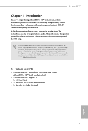
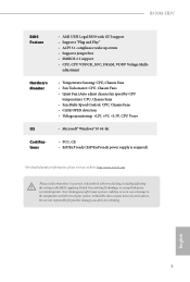
...the latest VGA cards and CPU support list on ASRock's website without notice. ASRock website http://www.asrock.com. 1.1 Package Contents • ASRock B550M-HDV Motherboard (Micro ATX Form Factor) • ASRock B550M-HDV Quick Installation Guide • ASRock B550M-HDV Support CD • 1 x I/O Panel Shield • 2 x Serial ATA (SATA) Data Cables (Optional) • 1 x Screw for purchasing ASRock B550M-HDV motherboard, a reliable motherboard produced under ASRock's consistently stringent quality control. Because the motherboard specifications and the BIOS software might be updated...
...the latest VGA cards and CPU support list on ASRock's website without notice. ASRock website http://www.asrock.com. 1.1 Package Contents • ASRock B550M-HDV Motherboard (Micro ATX Form Factor) • ASRock B550M-HDV Quick Installation Guide • ASRock B550M-HDV Support CD • 1 x I/O Panel Shield • 2 x Serial ATA (SATA) Data Cables (Optional) • 1 x Screw for purchasing ASRock B550M-HDV motherboard, a reliable motherboard produced under ASRock's consistently stringent quality control. Because the motherboard specifications and the BIOS software might be updated...

User Manual
Page 7
... Memory Support List on ASRock's website for more information. (http://www.asrock.com/) * Please refer to page 21 for DDR4 UDIMM maximum frequency support. • Max. capacity of system memory: 64GB • Supports Extreme Memory Profile (XMP) memory modules • 15μ Gold Contact in DIMM Slots English Expansion Slot AMD Ryzen series CPUs (Matisse) • 1 x PCI Express 4.0 x16 Slot (PCIE1: x16 mode)* AMD Ryzen series APUs (Renoir) • 1 x PCI Express 3.0 x16 Slot (PCIE1: x16 mode)* * Supports...
... Memory Support List on ASRock's website for more information. (http://www.asrock.com/) * Please refer to page 21 for DDR4 UDIMM maximum frequency support. • Max. capacity of system memory: 64GB • Supports Extreme Memory Profile (XMP) memory modules • 15μ Gold Contact in DIMM Slots English Expansion Slot AMD Ryzen series CPUs (Matisse) • 1 x PCI Express 4.0 x16 Slot (PCIE1: x16 mode)* AMD Ryzen series APUs (Renoir) • 1 x PCI Express 3.0 x16 Slot (PCIE1: x16 mode)* * Supports...

User Manual
Page 8
...-D with HDMI 2.1 Port • Supports Microsoft PlayReady® • 7.1 CH HD Audio (Realtek ALC887 Audio Codec) • Supports Surge Protection • PCIE x1 Gigabit LAN 10/100/1000 Mb/s • Realtek RTL8111H • Supports Wake-On-LAN • Supports Lightning/ESD Protection • Supports Energy Efficient Ethernet 802.3az • Supports PXE English 3 B550M-HDV Graphics Audio LAN • Integrated AMD RadeonTM Vega Series Graphics in Ryzen Series APU* * Actual support may vary by CPU...
...-D with HDMI 2.1 Port • Supports Microsoft PlayReady® • 7.1 CH HD Audio (Realtek ALC887 Audio Codec) • Supports Surge Protection • PCIE x1 Gigabit LAN 10/100/1000 Mb/s • Realtek RTL8111H • Supports Wake-On-LAN • Supports Lightning/ESD Protection • Supports Energy Efficient Ethernet 802.3az • Supports PXE English 3 B550M-HDV Graphics Audio LAN • Integrated AMD RadeonTM Vega Series Graphics in Ryzen Series APU* * Actual support may vary by CPU...

User Manual
Page 9
... and Speaker Header • 1 x CPU Fan Connector (4-pin) * The CPU Fan Connector supports the CPU fan of maximum 1A (12W) fan power. • 2 x Chassis Fan Connectors (4-pin) (Smart Fan Speed Con- Rear Panel I/O • 1 x PS/2 Mouse/Keyboard Port • 1 x D-Sub Port • 1 x DVI-D Port • 1 x HDMI Port • 2 x USB 2.0 Ports (Supports ESD Protection) • 4 x USB 3.2 Gen1 Ports (Supports ESD Protection) • 1 x RJ-45 LAN Port with LED (ACT/LINK LED and SPEED LED) • HD Audio Jacks: Line in use. • 1 x 24 pin ATX Power Connector • 1 x 4 pin 12V Power...
... and Speaker Header • 1 x CPU Fan Connector (4-pin) * The CPU Fan Connector supports the CPU fan of maximum 1A (12W) fan power. • 2 x Chassis Fan Connectors (4-pin) (Smart Fan Speed Con- Rear Panel I/O • 1 x PS/2 Mouse/Keyboard Port • 1 x D-Sub Port • 1 x DVI-D Port • 1 x HDMI Port • 2 x USB 2.0 Ports (Supports ESD Protection) • 4 x USB 3.2 Gen1 Ports (Supports ESD Protection) • 1 x RJ-45 LAN Port with LED (ACT/LINK LED and SPEED LED) • HD Audio Jacks: Line in use. • 1 x 24 pin ATX Power Connector • 1 x 4 pin 12V Power...
User Manual
Page 10
... 2.3 support • CPU, CPU VDDCR_SOC, DRAM, VDDP Voltage Multi- Overclocking may affect your system's stability, or even cause damage to the components and devices of your own risk and expense. adjustment • Temperature Sensing: CPU, Chassis Fans • Fan Tachometer: CPU, Chassis Fans • Quiet Fan (Auto adjust chassis fan speed by overclocking. B550M-HDV BIOS Feature Hardware Monitor OS Certifications • AMI UEFI Legal BIOS with overclocking, including adjusting the setting in the BIOS, applying Untied Overclocking Technology, or using third-party overclocking...
... 2.3 support • CPU, CPU VDDCR_SOC, DRAM, VDDP Voltage Multi- Overclocking may affect your system's stability, or even cause damage to the components and devices of your own risk and expense. adjustment • Temperature Sensing: CPU, Chassis Fans • Fan Tachometer: CPU, Chassis Fans • Quiet Fan (Auto adjust chassis fan speed by overclocking. B550M-HDV BIOS Feature Hardware Monitor OS Certifications • AMI UEFI Legal BIOS with overclocking, including adjusting the setting in the BIOS, applying Untied Overclocking Technology, or using third-party overclocking...

User Manual
Page 12
...Power Connector (ATX12V1) 2 CPU Fan Connector (CPU_FAN1) 3 2 x 288-pin DDR4 DIMM Slots (DDR4_A1, DDR4_B1) 4 ATX Power Connector (ATXPWR1) 5 USB 3.2 Gen1 Header (USB3_5_6) 6 SATA3 Connector (SATA3_3) 7 SATA3 Connector (SATA3_4) 8 SATA3 Connector (SATA3_1) 9 SATA3 Connector (SATA3_2) 10 System Panel Header (PANEL1) 11 Chassis Intrusion and Speaker Header (SPK_CI1) 12 Chassis Fan Connector (CHA_FAN2) 13 USB 2.0 Header (USB_3_4) 14 USB 2.0 Header (USB_5_6) 15 COM Port Header (COM1) 16 Clear CMOS Jumper (CLRCMOS1) 17 Front Panel Audio Header (HD_AUDIO1) 18 SPI TPM Header (SPI_TPM_J1) 19 Chassis Fan...
...Power Connector (ATX12V1) 2 CPU Fan Connector (CPU_FAN1) 3 2 x 288-pin DDR4 DIMM Slots (DDR4_A1, DDR4_B1) 4 ATX Power Connector (ATXPWR1) 5 USB 3.2 Gen1 Header (USB3_5_6) 6 SATA3 Connector (SATA3_3) 7 SATA3 Connector (SATA3_4) 8 SATA3 Connector (SATA3_1) 9 SATA3 Connector (SATA3_2) 10 System Panel Header (PANEL1) 11 Chassis Intrusion and Speaker Header (SPK_CI1) 12 Chassis Fan Connector (CHA_FAN2) 13 USB 2.0 Header (USB_3_4) 14 USB 2.0 Header (USB_5_6) 15 COM Port Header (COM1) 16 Clear CMOS Jumper (CLRCMOS1) 17 Front Panel Audio Header (HD_AUDIO1) 18 SPI TPM Header (SPI_TPM_J1) 19 Chassis Fan...

User Manual
Page 28
... sure that the power supply is switched off or the power cord is used for the card before you start the installation. English 23 PCIE2 (PCIe 3.0 x1 slot) is used for PCI Express x16 lane width graphics cards. Before installing an expansion card, please make necessary hardware settings for PCI Express x1 lane width cards. B550M-HDV 2.4 Expansion Slots (PCI Express Slots) There are 2 PCI Express slots on the motherboard. PCIe slots: PCIE1 (PCIe 4.0 x16 slot) is unplugged. PCIe Slot Configurations Ryzen Series CPUs (Matisse) Ryzen Series APUs (Renoir) PCIE1...
... sure that the power supply is switched off or the power cord is used for the card before you start the installation. English 23 PCIE2 (PCIe 3.0 x1 slot) is used for PCI Express x16 lane width graphics cards. Before installing an expansion card, please make necessary hardware settings for PCI Express x1 lane width cards. B550M-HDV 2.4 Expansion Slots (PCI Express Slots) There are 2 PCI Express slots on the motherboard. PCIe slots: PCIE1 (PCIe 4.0 x16 slot) is unplugged. PCIe Slot Configurations Ryzen Series CPUs (Matisse) Ryzen Series APUs (Renoir) PCIE1...

User Manual
Page 30
... NOT place jumper caps over the headers and connectors will cause permanent damage to this header according to the hard drive activity LED on when the hard drive is operating. B550M-HDV 2.6 Onboard Headers and Connectors Onboard headers and connectors are matched correctly. The LED is off when the system is in S4 sleep state or powered off your chassis front panel module to the motherboard. A front panel module mainly consists of power switch, reset switch, power LED, hard drive activity LED, speaker and etc...
... NOT place jumper caps over the headers and connectors will cause permanent damage to this header according to the hard drive activity LED on when the hard drive is operating. B550M-HDV 2.6 Onboard Headers and Connectors Onboard headers and connectors are matched correctly. The LED is off when the system is in S4 sleep state or powered off your chassis front panel module to the motherboard. A front panel module mainly consists of power switch, reset switch, power LED, hard drive activity LED, speaker and etc...

User Manual
Page 31
...+ Vbus IntA_PB_SSRXIntA_PB_SSRX+ GND IntA_PB_SSTXIntA_PB_SSTX+ GND IntA_PB_DIntA_PB_D+ Dummy 1 There is for internal storage devices with up to the front audio panel. USB 3.2 Gen1 Header (19-pin USB3_5_6) (see p.6, No. 17) 26 GND PRESENCE# MIC_RET OUT_RET 1 OUT2_L J_SENSE OUT2_R MIC2_R MIC2_L This header is one header on this header. English Each USB 2.0 header can support two ports. These four SATA3 connectors support SATA data cables for connecting audio devices to 6.0 Gb/s data transfer rate.
...+ Vbus IntA_PB_SSRXIntA_PB_SSRX+ GND IntA_PB_SSTXIntA_PB_SSTX+ GND IntA_PB_DIntA_PB_D+ Dummy 1 There is for internal storage devices with up to the front audio panel. USB 3.2 Gen1 Header (19-pin USB3_5_6) (see p.6, No. 17) 26 GND PRESENCE# MIC_RET OUT_RET 1 OUT2_L J_SENSE OUT2_R MIC2_R MIC2_L This header is one header on this header. English Each USB 2.0 header can support two ports. These four SATA3 connectors support SATA data cables for connecting audio devices to 6.0 Gb/s data transfer rate.
User Manual
Page 32
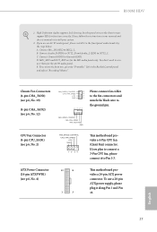
...) to function correctly. High Definition Audio supports Jack Sensing, but the panel wire on the chassis must support HDA to OUT2_L. Connect Mic_IN (MIC) to Ground (GND). If you use a 20-pin ATX power supply, please plug it along Pin 1 and Pin 13. English 27 Connect Ground (GND) to MIC2_L. E. B550M-HDV 1. C. FAN_SPEED_CONTROL CHA_FAN_SPEED FAN_VOLTAGE GND CPU Fan Connector (4-pin CPU_FAN1) (see p.6, No. 4) 12 24 1 13 This motherboard provides a 24-pin ATX power connector. ATX Power Connector (24-pin ATXPWR1) (see p.6, No...
...) to function correctly. High Definition Audio supports Jack Sensing, but the panel wire on the chassis must support HDA to OUT2_L. Connect Mic_IN (MIC) to Ground (GND). If you use a 20-pin ATX power supply, please plug it along Pin 1 and Pin 13. English 27 Connect Ground (GND) to MIC2_L. E. B550M-HDV 1. C. FAN_SPEED_CONTROL CHA_FAN_SPEED FAN_VOLTAGE GND CPU Fan Connector (4-pin CPU_FAN1) (see p.6, No. 4) 12 24 1 13 This motherboard provides a 24-pin ATX power connector. ATX Power Connector (24-pin ATXPWR1) (see p.6, No...

User Manual
Page 38
... application software that enhance the motherboard's features. Drivers Menu The drivers compatible to your system will be auto-detected and listed on the file "ASRSETUP.EXE" in your CD-ROM drive. B550M-HDV Chapter 3 Software and Utilities Operation 3.1 Installing Drivers The Support CD that comes with the motherboard contains necessary drivers and useful utilities that the motherboard supports. If the Main Menu does not appear automatically, locate and double click on the support CD driver page. Click on a specific item...
... application software that enhance the motherboard's features. Drivers Menu The drivers compatible to your system will be auto-detected and listed on the file "ASRSETUP.EXE" in your CD-ROM drive. B550M-HDV Chapter 3 Software and Utilities Operation 3.1 Installing Drivers The Support CD that comes with the motherboard contains necessary drivers and useful utilities that the motherboard supports. If the Main Menu does not appear automatically, locate and double click on the support CD driver page. Click on a specific item...
User Manual
Page 48
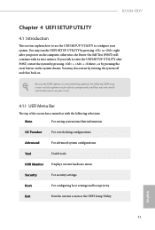
... H/W Monitor Displays current hardware status Security For security settings Boot For configuring boot settings and boot priority Exit Exit the current screen or the UEFI Setup Utility English 43 You may not exactly match what you wish to configure your screen. 4.1.1 UEFI Menu Bar The top of the screen has a menu bar with its test routines. B550M-HDV Chapter 4 UEFI SETUP UTILITY 4.1 Introduction This section explains how to use the UEFI SETUP UTILITY to enter the UEFI SETUP UTILITY after you power...
... H/W Monitor Displays current hardware status Security For security settings Boot For configuring boot settings and boot priority Exit Exit the current screen or the UEFI Setup Utility English 43 You may not exactly match what you wish to configure your screen. 4.1.1 UEFI Menu Bar The top of the screen has a menu bar with its test routines. B550M-HDV Chapter 4 UEFI SETUP UTILITY 4.1 Introduction This section explains how to use the UEFI SETUP UTILITY to enter the UEFI SETUP UTILITY after you power...
User Manual
Page 52
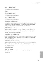
... memory and perform beyond standard specifications. 47 English CLD0 VDDP Voltage Control AMD Overclocking Setup VDDP is derived from the CPU SoC/Uncore Voltage (VDD_SOC). It is a voltage for the data portion of the Infinity Fabric. VDD_SOC also determines the GPU voltage on processors with integrated graphics. VDDG can approach but not exceed VDD_SOC. DRAM Information Load XMP Setting Load XMP settings to support memory and Infinity Fabric overclocking. B550M-HDV CCX1 Frequency (MHz) Use...
... memory and perform beyond standard specifications. 47 English CLD0 VDDP Voltage Control AMD Overclocking Setup VDDP is derived from the CPU SoC/Uncore Voltage (VDD_SOC). It is a voltage for the data portion of the Infinity Fabric. VDD_SOC also determines the GPU voltage on processors with integrated graphics. VDDG can approach but not exceed VDD_SOC. DRAM Information Load XMP Setting Load XMP settings to support memory and Infinity Fabric overclocking. B550M-HDV CCX1 Frequency (MHz) Use...

User Manual
Page 55
... default value is set to [Enabled], a VMM (Virtual Machine Architecture)can be used to disable symmetric multithreading. Coniguration options: [Enabled] and [Disabled]. SMT Mode This item can utilize the additional hardware capabilities provided by AMD-V. SVM Mode When this to enable or disable the generation of ACPI_PPC, _PSS, and _PCT objects. Warning: S3 is not supported on systems where SMT is needed after selecting [Auto]. To re-enable...
... default value is set to [Enabled], a VMM (Virtual Machine Architecture)can be used to disable symmetric multithreading. Coniguration options: [Enabled] and [Disabled]. SMT Mode This item can utilize the additional hardware capabilities provided by AMD-V. SVM Mode When this to enable or disable the generation of ACPI_PPC, _PSS, and _PCT objects. Warning: S3 is not supported on systems where SMT is needed after selecting [Auto]. To re-enable...

User Manual
Page 64
After copying the drivers please change the SATA mode to securely erase SSD. SSD Secure Erase Tool Use this tool to RAID, then you can start installing the operating system in your USB storage device and run Instant Flash to your UEFI. 59 English Instant Flash Save UEFI files in RAID mode. 4.5 Tools B550M-HDV Easy RAID Installer Easy RAID Installer helps you to copy the RAID driver from the support CD to update your USB storage device. NVME Sanitization Tool After you sanitize SSD, all user data will be permantly destroyed on the SSD and cannot be recovered.
After copying the drivers please change the SATA mode to securely erase SSD. SSD Secure Erase Tool Use this tool to RAID, then you can start installing the operating system in your USB storage device and run Instant Flash to your UEFI. 59 English Instant Flash Save UEFI files in RAID mode. 4.5 Tools B550M-HDV Easy RAID Installer Easy RAID Installer helps you to copy the RAID driver from the support CD to update your USB storage device. NVME Sanitization Tool After you sanitize SSD, all user data will be permantly destroyed on the SSD and cannot be recovered.

RAID Installation Guide
Page 2
.... Hot-Plug any fault tolerance. AMD BIOS RAID Installation Guide AMD BIOS RAID Installation Guide is called data mirroring that optimizes two identical hard disk drives to a second drive. For optimal performance, please install identical drives of the RAID 0 Disk will direct all applications to the surviving drive as it does not provide any HDDs of the same model and capacity when creating a RAID set the option to RAID mode by following the detailed instruction of the "User Manual" in...
.... Hot-Plug any fault tolerance. AMD BIOS RAID Installation Guide AMD BIOS RAID Installation Guide is called data mirroring that optimizes two identical hard disk drives to a second drive. For optimal performance, please install identical drives of the RAID 0 Disk will direct all applications to the surviving drive as it does not provide any HDDs of the same model and capacity when creating a RAID set the option to RAID mode by following the detailed instruction of the "User Manual" in...

RAID Installation Guide
Page 8
... system boot, press or key to Tools Easy RAID Installer F. Go to enter UEFI setup utility. Follow instructions to find the driver inside your USB flash disk. Insert the Support CD into one of the USB port. E. B. Plug a USB drive into the DVD-ROM drive. STEP 4: Windows installation A. C. B. D. Please install the DVD-ROM. Click to finish the driver copy process. During Windows installation process, when Disk selection page show up, please click . A. Please download the "SATA Floppy Imaged driver" from ASRock's website A. STEP 3.1: Copy RAID driver...
... system boot, press or key to Tools Easy RAID Installer F. Go to enter UEFI setup utility. Follow instructions to find the driver inside your USB flash disk. Insert the Support CD into one of the USB port. E. B. Plug a USB drive into the DVD-ROM drive. STEP 4: Windows installation A. C. B. D. Please install the DVD-ROM. Click to finish the driver copy process. During Windows installation process, when Disk selection page show up, please click . A. Please download the "SATA Floppy Imaged driver" from ASRock's website A. STEP 3.1: Copy RAID driver...

RAID Installation Guide
Page 14
... DVD-ROM. E. Follow instructions to exit. Select "Create Array". Plug a USB drive into the DVD-ROM drive. D. Go to enter UEFI setup utility. A. B. During system boot, press or key to Tools Easy RAID Installer F. Insert the Support CD into one of the USB port. STEP 2.1: Copy RAID driver to a USB flash drive You can choose either STEP2.1 or STEP2.2 to finish the configuration. STEP 2.2: Download driver from ASRock's website and unzip the file into your USB flash disk. 14 C. Please download the "SATA Floppy Imaged driver...
... DVD-ROM. E. Follow instructions to exit. Select "Create Array". Plug a USB drive into the DVD-ROM drive. D. Go to enter UEFI setup utility. A. B. During system boot, press or key to Tools Easy RAID Installer F. Insert the Support CD into one of the USB port. STEP 2.1: Copy RAID driver to a USB flash drive You can choose either STEP2.1 or STEP2.2 to finish the configuration. STEP 2.2: Download driver from ASRock's website and unzip the file into your USB flash disk. 14 C. Please download the "SATA Floppy Imaged driver...

RAID Installation Guide
Page 15
... drivers must be loaded. Using SATA/NVMe RAID driver package (version 9.2.0.127) from . During Windows installation process, when Disk selection page show up, please click . While this picture. If the system restarts at this point, then please open the boot menu that is shown in this system is the first. B. This is booting, please press F11 to boot from AMD website. It should list the USB drive as a UEFI device...
... drivers must be loaded. Using SATA/NVMe RAID driver package (version 9.2.0.127) from . During Windows installation process, when Disk selection page show up, please click . While this picture. If the system restarts at this point, then please open the boot menu that is shown in this system is the first. B. This is booting, please press F11 to boot from AMD website. It should list the USB drive as a UEFI device...


