User Manual
Page 5
... 1.2 Specifications 2 1.3 Motherboard Layout 6 1.4 I/O Panel 9 Chapter 2 Installation 11 2.1 Installing the CPU 12 2.2 Installing the CPU Fan and Heatsink 15 2.3 Installing Memory Modules (DIMM) 16 2.4 Expansion Slots (PCI and PCIe Slots) 18 2.5 Jumpers Setup 19 2.6 Onboard Headers and Connectors 20 2.7 M.2_SSD (NGFF) Module Installation Guide (M2_1) 25 Chapter 3 Software and Utilities Operation 29 3.1 Installing Drivers 29 3.2 ASRock Motherboard Utility (A-Tuning) 30 3.2.1 Installing ASRock Motherboard Utility (A-Tuning) 30 3.2.2 Using ASRock Motherboard Utility...
... 1.2 Specifications 2 1.3 Motherboard Layout 6 1.4 I/O Panel 9 Chapter 2 Installation 11 2.1 Installing the CPU 12 2.2 Installing the CPU Fan and Heatsink 15 2.3 Installing Memory Modules (DIMM) 16 2.4 Expansion Slots (PCI and PCIe Slots) 18 2.5 Jumpers Setup 19 2.6 Onboard Headers and Connectors 20 2.7 M.2_SSD (NGFF) Module Installation Guide (M2_1) 25 Chapter 3 Software and Utilities Operation 29 3.1 Installing Drivers 29 3.2 ASRock Motherboard Utility (A-Tuning) 30 3.2.1 Installing ASRock Motherboard Utility (A-Tuning) 30 3.2.2 Using ASRock Motherboard Utility...
User Manual
Page 7
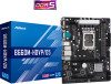
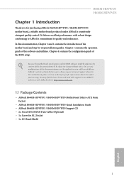
... Quick Installation Guide • ASRock B660M-HDVP/D5 / H610M-HDVP/D5 Support CD • 2 x Serial ATA (SATA) Data Cables (Optional) • 1 x Screw for purchasing ASRock B660M-HDVP/D5 / H610M-HDVP/D5 motherboard, a reliable motherboard produced under ASRock's consistently stringent quality control. B660M-HDVP/D5 H610M-HDVP/D5 Chapter 1 Introduction Thank you are using. In this motherboard, please visit our website for specific information about the model you for M.2 Socket • 1 x I/O Panel Shield 1 English In case any modifications of this documentation will be updated...
... Quick Installation Guide • ASRock B660M-HDVP/D5 / H610M-HDVP/D5 Support CD • 2 x Serial ATA (SATA) Data Cables (Optional) • 1 x Screw for purchasing ASRock B660M-HDVP/D5 / H610M-HDVP/D5 motherboard, a reliable motherboard produced under ASRock's consistently stringent quality control. B660M-HDVP/D5 H610M-HDVP/D5 Chapter 1 Introduction Thank you are using. In this motherboard, please visit our website for specific information about the model you for M.2 Socket • 1 x I/O Panel Shield 1 English In case any modifications of this documentation will be updated...
User Manual
Page 8
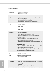
...://www.asrock.com/) H610M-HDVP/D5: • Supports DDR5 non-ECC, un-buffered memory up to 4800* * Supports DDR5 4800 (1DPC) natively. * Please refer to Memory Support List on ASRock's website for more information. (http://www.asrock.com/) Expansion Slot • 1 x PCIe Gen4x16 Slot * Supports NVMe SSD as boot disks • 2 x PCIe Gen3x1 Slots • 1 x PCI Slot Graphics • Intel® UHD Graphics Built-in Visuals and the VGA outputs can be supported only with processors...
...://www.asrock.com/) H610M-HDVP/D5: • Supports DDR5 non-ECC, un-buffered memory up to 4800* * Supports DDR5 4800 (1DPC) natively. * Please refer to Memory Support List on ASRock's website for more information. (http://www.asrock.com/) Expansion Slot • 1 x PCIe Gen4x16 Slot * Supports NVMe SSD as boot disks • 2 x PCIe Gen3x1 Slots • 1 x PCI Slot Graphics • Intel® UHD Graphics Built-in Visuals and the VGA outputs can be supported only with processors...
User Manual
Page 10
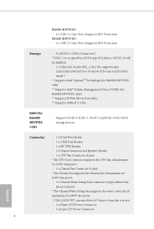
...Key M), supports type 2242/2260/2280 SATA3 6.0 Gb/s & PCIe Gen3 x4 (32 Gb/s) mode** ** Supports Intel® OptaneTM Technology (for B660M-HDVP/D5 only) ** Supports Intel® Volume Management Device (VMD) (for B660M-HDVP/D5 only) ** Supports NVMe SSD as boot disks ** Supports ASRock U.2 Kit RAID (for B660MHDVP/D5 only) • Supports RAID 0, RAID 1, RAID 5 and RAID 10 for SATA storage devices Connector • 1 x Print Port Header • 1 x COM Port Header • 1 x SPI TPM Header • 1 x Chassis Intrusion and Speaker Header • 1 x CPU Fan Connector (4-pin) * The CPU Fan...
...Key M), supports type 2242/2260/2280 SATA3 6.0 Gb/s & PCIe Gen3 x4 (32 Gb/s) mode** ** Supports Intel® OptaneTM Technology (for B660M-HDVP/D5 only) ** Supports Intel® Volume Management Device (VMD) (for B660M-HDVP/D5 only) ** Supports NVMe SSD as boot disks ** Supports ASRock U.2 Kit RAID (for B660MHDVP/D5 only) • Supports RAID 0, RAID 1, RAID 5 and RAID 10 for SATA storage devices Connector • 1 x Print Port Header • 1 x COM Port Header • 1 x SPI TPM Header • 1 x Chassis Intrusion and Speaker Header • 1 x CPU Fan Connector (4-pin) * The CPU Fan...
User Manual
Page 11
... Core/Cache, CPU GT, VDD_CPU, VCCIN AUX, +1.05V PROC, +0.82V PCH , +1.05V PCH Voltage Multiadjustment Hardware Monitor • Fan Tachometer: CPU, Chassis, Chassis/Water Pump Fans • Quiet Fan (Auto adjust chassis fan speed by overclocking. 5 English We are not responsible for possible damage caused by CPU tempera- B660M-HDVP/D5 H610M-HDVP/D5 • 1 x Front Panel Audio Connector • 2 x USB 2.0 Headers (Support 4 USB 2.0 ports) (Supports ESD Protection) • 1 x USB 3.2 Gen1 Header (Supports 2 USB 3.2 Gen1 ports) (Supports ESD Protection) BIOS Feature • AMI UEFI...
... Core/Cache, CPU GT, VDD_CPU, VCCIN AUX, +1.05V PROC, +0.82V PCH , +1.05V PCH Voltage Multiadjustment Hardware Monitor • Fan Tachometer: CPU, Chassis, Chassis/Water Pump Fans • Quiet Fan (Auto adjust chassis fan speed by overclocking. 5 English We are not responsible for possible damage caused by CPU tempera- B660M-HDVP/D5 H610M-HDVP/D5 • 1 x Front Panel Audio Connector • 2 x USB 2.0 Headers (Support 4 USB 2.0 ports) (Supports ESD Protection) • 1 x USB 3.2 Gen1 Header (Supports 2 USB 3.2 Gen1 ports) (Supports ESD Protection) BIOS Feature • AMI UEFI...
User Manual
Page 12
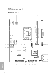
... 1.3 Motherboard Layout B660M-HDVP/D5 1 ATX12V1 2 3 CPU_FAN1 B660M-HDVP/D5 DDR5_A1 (64 bit, 288-pin module) DDR5_B1 (64 bit, 288-pin module) ATXPWR1 HDMI1 COM1 DP1 4 PS2 Mouse PS2 Keyboard USB 3.2 Gen1 USB3_3456 CHA_FAN1/WP Top: RJ-45 USB 2.0 T: USB_1 B: USB_2 20 5 M2_1 RoHS USB3_1_2 1 Top: LINE IN Center: FRONT Bottom: MIC IN 19 1 HD_AUDIO1 PCIE1 CMOS AUDIO CODEC PCIE2 Battery Intel PCIE3 B660 6 SATA3_2 PCI1 SATA3_3 7 SPI_TPM_J1 1 BIOS ROM...
... 1.3 Motherboard Layout B660M-HDVP/D5 1 ATX12V1 2 3 CPU_FAN1 B660M-HDVP/D5 DDR5_A1 (64 bit, 288-pin module) DDR5_B1 (64 bit, 288-pin module) ATXPWR1 HDMI1 COM1 DP1 4 PS2 Mouse PS2 Keyboard USB 3.2 Gen1 USB3_3456 CHA_FAN1/WP Top: RJ-45 USB 2.0 T: USB_1 B: USB_2 20 5 M2_1 RoHS USB3_1_2 1 Top: LINE IN Center: FRONT Bottom: MIC IN 19 1 HD_AUDIO1 PCIE1 CMOS AUDIO CODEC PCIE2 Battery Intel PCIE3 B660 6 SATA3_2 PCI1 SATA3_3 7 SPI_TPM_J1 1 BIOS ROM...
User Manual
Page 13
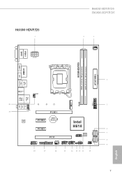
...-HDVP/D5 2 3 CPU_FAN1 H610M-HDVP/D5 DDR5_A1 (64 bit, 288-pin module) DDR5_B1 (64 bit, 288-pin module) ATXPWR1 HDMI1 COM1 DP1 4 PS2 Mouse PS2 Keyboard USB 3.2 Gen1 USB3_34 CHA_FAN1/WP Top: RJ-45 USB 2.0 T: USB_1 B: USB_2 20 5 M2_1 RoHS USB3_1_2 1 Top: LINE IN Center: FRONT Bottom: MIC IN 19 1 HD_AUDIO1 PCIE1 CMOS AUDIO CODEC PCIE2 Battery Intel PCIE3 H610 6 SATA3_2 PCI1 SATA3_3 7 SPI_TPM_J1 1 BIOS ROM...
...-HDVP/D5 2 3 CPU_FAN1 H610M-HDVP/D5 DDR5_A1 (64 bit, 288-pin module) DDR5_B1 (64 bit, 288-pin module) ATXPWR1 HDMI1 COM1 DP1 4 PS2 Mouse PS2 Keyboard USB 3.2 Gen1 USB3_34 CHA_FAN1/WP Top: RJ-45 USB 2.0 T: USB_1 B: USB_2 20 5 M2_1 RoHS USB3_1_2 1 Top: LINE IN Center: FRONT Bottom: MIC IN 19 1 HD_AUDIO1 PCIE1 CMOS AUDIO CODEC PCIE2 Battery Intel PCIE3 H610 6 SATA3_2 PCI1 SATA3_3 7 SPI_TPM_J1 1 BIOS ROM...
User Manual
Page 14
...Power Connector (ATX12V1) 2 2 x 288-pin DDR5 DIMM Slots (DDR5_A1, DDR5_B1) 3 CPU Fan Connector (CPU_FAN1) 4 ATX Power Connector (ATXPWR1) 5 USB 3.2 Gen1 Header (USB3_1_2) 6 SATA3 Connector (SATA3_3) 7 SATA3 Connector (SATA3_2) 8 SATA3 Connector (SATA3_0) 9 SATA3 Connector (SATA3_1) 10 Chassis Intrusion and Speaker Header (SPK_CI1) 11 SPI TPM Header (SPI_TPM_J1) 12 System Panel Header (PANEL1) 13 Clear CMOS Jumper (CLRMOS1) 14 USB 2.0 Header (USB_5_6) 15 USB 2.0 Header (USB_3_4) 16 Chassis Fan Connector (CHA_FAN2) 17 Print Port Header (LPT1) 18 COM Port Header (COM2) 19 Front Panel Audio Header...
...Power Connector (ATX12V1) 2 2 x 288-pin DDR5 DIMM Slots (DDR5_A1, DDR5_B1) 3 CPU Fan Connector (CPU_FAN1) 4 ATX Power Connector (ATXPWR1) 5 USB 3.2 Gen1 Header (USB3_1_2) 6 SATA3 Connector (SATA3_3) 7 SATA3 Connector (SATA3_2) 8 SATA3 Connector (SATA3_0) 9 SATA3 Connector (SATA3_1) 10 Chassis Intrusion and Speaker Header (SPK_CI1) 11 SPI TPM Header (SPI_TPM_J1) 12 System Panel Header (PANEL1) 13 Clear CMOS Jumper (CLRMOS1) 14 USB 2.0 Header (USB_5_6) 15 USB 2.0 Header (USB_3_4) 16 Chassis Fan Connector (CHA_FAN2) 17 Print Port Header (LPT1) 18 COM Port Header (COM2) 19 Front Panel Audio Header...
User Manual
Page 25
... BIOS option "Clear Status" to clear the CMOS when you just finish updating the BIOS, you must boot up the system first, and then shut it down before you update the BIOS. B660M-HDVP/D5 H610M-HDVP/D5 2.5 Jumpers Setup The illustration shows how jumpers are setup. If no jumper cap is placed on CLRMOS1 for 15 seconds, use a jumper cap to default setup, please turn off the computer and unplug the power cord from the power supply...
... BIOS option "Clear Status" to clear the CMOS when you just finish updating the BIOS, you must boot up the system first, and then shut it down before you update the BIOS. B660M-HDVP/D5 H610M-HDVP/D5 2.5 Jumpers Setup The illustration shows how jumpers are setup. If no jumper cap is placed on CLRMOS1 for 15 seconds, use a jumper cap to default setup, please turn off the computer and unplug the power cord from the power supply...
User Manual
Page 27
... a SATA-type M.2 device, SATA3_0 will be disabled. English 21 Serial ATA3 Connectors Vertical: (SATA3_0: see p.6, 7, No. 8) (SATA3_1: see p.6, 7, No. 9) (SATA3_2: see p.6, 7, No. 7) (SATA3_3: see p.6, 7, No. 6) SATA3_1 SATA3_3 SATA3_0 SATA3_2 These four SATA3 connectors support SATA data cables for internal storage devices with up to this motherboard.Each USB 2.0 header can support two ports. B660M-HDVP/D5 H610M-HDVP/D5 Chassis Intrusion and Speaker Header (7-pin SPK_CI1) (see p.6, 7, No. 10) SPEAKER DUMMY DUMMY +5V 1 SIGNAL GND DUMMY Please connect the chassis...
... a SATA-type M.2 device, SATA3_0 will be disabled. English 21 Serial ATA3 Connectors Vertical: (SATA3_0: see p.6, 7, No. 8) (SATA3_1: see p.6, 7, No. 9) (SATA3_2: see p.6, 7, No. 7) (SATA3_3: see p.6, 7, No. 6) SATA3_1 SATA3_3 SATA3_0 SATA3_2 These four SATA3 connectors support SATA data cables for internal storage devices with up to this motherboard.Each USB 2.0 header can support two ports. B660M-HDVP/D5 H610M-HDVP/D5 Chassis Intrusion and Speaker Header (7-pin SPK_CI1) (see p.6, 7, No. 10) SPEAKER DUMMY DUMMY +5V 1 SIGNAL GND DUMMY Please connect the chassis...
User Manual
Page 28
... connecting audio devices to Pin 1-3. 22 English If you plan to connect a 3-Pin CPU fan, please connect it to install your system. 2. Please follow the instructions in the Realtek Control panel and adjust "Recording Volume". MIC_RET and OUT_RET are for the AC'97 audio panel. Front Panel Audio Header (9-pin HD_AUDIO1) OUT_RET (see p.6, 7, No. 3) 4 3 21 GND +12V CPU_FAN_SPEED FAN_SPEED_CONTROL This motherboard provides a 4-Pin CPU fan (Quiet Fan) connector. High Definition Audio supports Jack Sensing, but the panel wire on the chassis...
... connecting audio devices to Pin 1-3. 22 English If you plan to connect a 3-Pin CPU fan, please connect it to install your system. 2. Please follow the instructions in the Realtek Control panel and adjust "Recording Volume". MIC_RET and OUT_RET are for the AC'97 audio panel. Front Panel Audio Header (9-pin HD_AUDIO1) OUT_RET (see p.6, 7, No. 3) 4 3 21 GND +12V CPU_FAN_SPEED FAN_SPEED_CONTROL This motherboard provides a 4-Pin CPU fan (Quiet Fan) connector. High Definition Audio supports Jack Sensing, but the panel wire on the chassis...
User Manual
Page 29
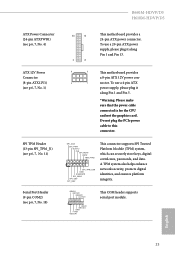
...) Serial Port Header (9-pin COM2) (see p.6, 7, No. 4) 12 24 1 13 This motherboard provides a 24-pin ATX power connector. B660M-HDVP/D5 H610M-HDVP/D5 ATX Power Connector (24-pin ATXPWR1) (see p.6, 7, No. 18) SPI_DQ3 SPI_PWR Dummy CLK SPI_MOSI RST# TPM_PIRQ 1 SPI_TPM_CS# GND RSMRST# SPI_MISO SPI_CS0 SPI_DQ2 This connector supports SPI Trusted Platform Module (TPM) system, which can securely store keys, digital certificates, passwords, and data. To use a 20-pin ATX power supply, please plug it along Pin 1 and Pin 13. ATX...
...) Serial Port Header (9-pin COM2) (see p.6, 7, No. 4) 12 24 1 13 This motherboard provides a 24-pin ATX power connector. B660M-HDVP/D5 H610M-HDVP/D5 ATX Power Connector (24-pin ATXPWR1) (see p.6, 7, No. 18) SPI_DQ3 SPI_PWR Dummy CLK SPI_MOSI RST# TPM_PIRQ 1 SPI_TPM_CS# GND RSMRST# SPI_MISO SPI_CS0 SPI_DQ2 This connector supports SPI Trusted Platform Module (TPM) system, which can securely store keys, digital certificates, passwords, and data. To use a 20-pin ATX power supply, please plug it along Pin 1 and Pin 13. ATX...
User Manual
Page 35
If the Main Menu does not appear automatically, locate and double click on the support CD driver page. Therefore, the drivers you install can work properly. B660M-HDVP/D5 H610M-HDVP/D5 Chapter 3 Software and Utilities Operation 3.1 Installing Drivers The Support CD that comes with the motherboard contains necessary drivers and useful utilities that the motherboard supports. Running The Support CD To begin using the support CD, insert the CD into your computer. The CD automatically displays the Main Menu if...
If the Main Menu does not appear automatically, locate and double click on the support CD driver page. Therefore, the drivers you install can work properly. B660M-HDVP/D5 H610M-HDVP/D5 Chapter 3 Software and Utilities Operation 3.1 Installing Drivers The Support CD that comes with the motherboard contains necessary drivers and useful utilities that the motherboard supports. Running The Support CD To begin using the support CD, insert the CD into your computer. The CD automatically displays the Main Menu if...
User Manual
Page 70
... disable the integrated graphics when an external graphics card is installed. 64 English IGPU Multi-Monitor Select disable to keep the integrated graphics enabled at all CPU downstream devices. Set to Auto to the integrated graphics processor when the system boots up. PCIE3 Link Speed Select the link speed for PCIE1. PCIE ASPM Support This option enables/disables the ASPM support for all PCH PCIE devices. Auto mode is allocated to enable onboard HD audio and automatically disable it when a sound card is installed. Share Memory Configure...
... disable the integrated graphics when an external graphics card is installed. 64 English IGPU Multi-Monitor Select disable to keep the integrated graphics enabled at all CPU downstream devices. Set to Auto to the integrated graphics processor when the system boots up. PCIE3 Link Speed Select the link speed for PCIE1. PCIE ASPM Support This option enables/disables the ASPM support for all PCH PCIE devices. Auto mode is allocated to enable onboard HD audio and automatically disable it when a sound card is installed. Share Memory Configure...
User Manual
Page 73
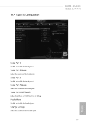
Serial Port Address Select the address of the Serial port. Serial Port/UART Switch Select Serial Port or UART for Port 80 debug Parallel Port Enable or disable the Parallel port. Serial Port Address Select the address of the Serial port. Change Settings Select the address of the Parallel port. 67 English 4.6.4 Super IO Configuration B660M-HDVP/D5 H610M-HDVP/D5 Serial Port 1 Enable or disable the Serial port 1. Serial Port 2 Enable or disable the Serial port 2.
Serial Port Address Select the address of the Serial port. Serial Port/UART Switch Select Serial Port or UART for Port 80 debug Parallel Port Enable or disable the Parallel port. Serial Port Address Select the address of the Serial port. Change Settings Select the address of the Parallel port. 67 English 4.6.4 Super IO Configuration B660M-HDVP/D5 H610M-HDVP/D5 Serial Port 1 Enable or disable the Serial port 1. Serial Port 2 Enable or disable the Serial port 2.
User Manual
Page 78
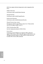
... to TPM 2.0 Device Device Select Use this item to tell OS to change State of the Device. If TPM 2.0 devices are not found, TPM 1.2 devices will restrict support to TPM 1.2 devices. TPM 1.2 will be supported. Auto will restrict support to TPM 2.0 devices. TPM 2.0 will support both with the default set to TPM 2.0 devices. Physical Presence Spec version Select this item to select the TPM device to enable or disable Endorsement Hierarchy. Please...
... to TPM 2.0 Device Device Select Use this item to tell OS to change State of the Device. If TPM 2.0 devices are not found, TPM 1.2 devices will restrict support to TPM 1.2 devices. TPM 1.2 will be supported. Auto will restrict support to TPM 2.0 devices. TPM 2.0 will support both with the default set to TPM 2.0 devices. Physical Presence Spec version Select this item to select the TPM device to enable or disable Endorsement Hierarchy. Please...
User Manual
Page 79
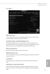
... the RAID driver from the support CD to update your UEFI. SSD Secure Erase Tool All the SSD's listed that supports Secure Erase function. Please setup network configuration before using Internet Flash. 73 English Easy RAID Installer (for you. 4.7 Tools B660M-HDVP/D5 H610M-HDVP/D5 UEFI Tech Service Contact ASRock Tech Service if you are having trouble with your USB storage device. Instant Flash Save UEFI files in RAID mode. After copying the drivers please change the SATA mode to RAID, then you Sanitize SSD, all user...
... the RAID driver from the support CD to update your UEFI. SSD Secure Erase Tool All the SSD's listed that supports Secure Erase function. Please setup network configuration before using Internet Flash. 73 English Easy RAID Installer (for you. 4.7 Tools B660M-HDVP/D5 H610M-HDVP/D5 UEFI Tech Service Contact ASRock Tech Service if you are having trouble with your USB storage device. Instant Flash Save UEFI files in RAID mode. After copying the drivers please change the SATA mode to RAID, then you Sanitize SSD, all user...
User Manual
Page 80
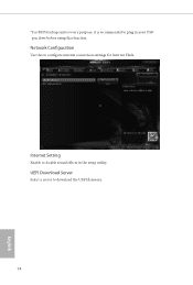
Internet Setting Enable or disable sound effects in your USB pen drive before using this to download the UEFI firmware. 74 English UEFI Download Server Select a server to configure internet connection settings for Internet Flash. Network Configuration Use this function. *For BIOS backup and recovery purpose, it is recommended to plug in the setup utility.
Internet Setting Enable or disable sound effects in your USB pen drive before using this to download the UEFI firmware. 74 English UEFI Download Server Select a server to configure internet connection settings for Internet Flash. Network Configuration Use this function. *For BIOS backup and recovery purpose, it is recommended to plug in the setup utility.

User Manual
Page 83
User Password Set or change the password for the user account. Intel(R) Platform Trust Technology Enable/disable Intel PTT in the UEFI Setup Utility. Disable this item to remove the password. Supervisor Password Set or change the password for the administrator account. Leave it blank and press enter to enable or disable support for the system. B660M-HDVP/D5 H610M-HDVP/D5 4.9 Security Screen In this section you may also clear the user password. Secure Boot Use this option to change the supervisor/user password for Secure Boot. Only the...
User Password Set or change the password for the user account. Intel(R) Platform Trust Technology Enable/disable Intel PTT in the UEFI Setup Utility. Disable this item to remove the password. Supervisor Password Set or change the password for the administrator account. Leave it blank and press enter to enable or disable support for the system. B660M-HDVP/D5 H610M-HDVP/D5 4.9 Security Screen In this section you may also clear the user password. Secure Boot Use this option to change the supervisor/user password for Secure Boot. Only the...
Intel Rapid Storage Guide
Page 13
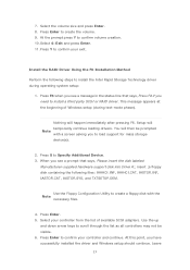
... insert the disk labeled Manufacturer-supplied hardware support disk into Drive A:, insert ;a floppy disk containing the following steps to scroll through the list as all controllers may not be prompted Note with the Note necessary files. 4. You will then be visible. 6. Use the up and down arrow keys to install the Intel Rapid Storage Technology driver during text-mode phase). Press Enter to confirm your exit. Setup will happen...
... insert the disk labeled Manufacturer-supplied hardware support disk into Drive A:, insert ;a floppy disk containing the following steps to scroll through the list as all controllers may not be prompted Note with the Note necessary files. 4. You will then be visible. 6. Use the up and down arrow keys to install the Intel Rapid Storage Technology driver during text-mode phase). Press Enter to confirm your exit. Setup will happen...


