User Manual
Page 5
... the latest VGA cards and CPU support lists on ASRock website without notice. It delivers excellent performance with robust design conforming to ASRock's commitment to change without further notice. In this motherboard, please visit our website for specific information about the model you for purchasing ASRock G41M-PS motherboard, a reliable motherboard produced under ASRock's consistently stringent quality control...
... the latest VGA cards and CPU support lists on ASRock website without notice. It delivers excellent performance with robust design conforming to ASRock's commitment to change without further notice. In this motherboard, please visit our website for specific information about the model you for purchasing ASRock G41M-PS motherboard, a reliable motherboard produced under ASRock's consistently stringent quality control...

User Manual
Page 6
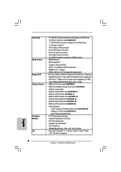
... x 19.1 cm - resolution up to -Use USB 2.0 Ports - 1 x RJ-45 LAN Port with max. 1.2 Specifications Platform CPU Chipset Memory Expansion Slot Graphics Audio LAN Rear Panel I /O Panel - 1 x PS/2 Mouse Port - 1 x PS/2 Keyboard Port - 1 x Parallel Port (ECP/EPP Support) - 1 x Serial Port: COM1 - 1 x VGA Port - 4 x Ready-to 2048x1536 @ 60Hz - 5.1 CH HD Audio (VIA® VT1705 Audio...
... x 19.1 cm - resolution up to -Use USB 2.0 Ports - 1 x RJ-45 LAN Port with max. 1.2 Specifications Platform CPU Chipset Memory Expansion Slot Graphics Audio LAN Rear Panel I /O Panel - 1 x PS/2 Mouse Port - 1 x PS/2 Keyboard Port - 1 x Parallel Port (ECP/EPP Support) - 1 x Serial Port: COM1 - 1 x VGA Port - 4 x Ready-to 2048x1536 @ 60Hz - 5.1 CH HD Audio (VIA® VT1705 Audio...

User Manual
Page 7
... RAID and "Hot Plug" functions) (see CAUTION 15) - OEM) - ASRock XFast LAN (see CAUTION 7) - 1 x ATA100 IDE connector (supports 2 x IDE devices) - 1 x Floppy connector - ASRock U-COP (see CAUTION 14) - Chassis Fan Tachometer - AMI Legal BIOS - ASRock Instant Boot - ASRock XFast USB (see CAUTION 17) - CPU Temperature Sensing - CPU Fan Tachometer - Supports "Plug and Play" - Creative Sound Blaster X-Fi MB Trial...
... RAID and "Hot Plug" functions) (see CAUTION 15) - OEM) - ASRock XFast LAN (see CAUTION 7) - 1 x ATA100 IDE connector (supports 2 x IDE devices) - 1 x Floppy connector - ASRock U-COP (see CAUTION 14) - Chassis Fan Tachometer - AMI Legal BIOS - ASRock Instant Boot - ASRock XFast USB (see CAUTION 17) - CPU Temperature Sensing - CPU Fan Tachometer - Supports "Plug and Play" - Creative Sound Blaster X-Fi MB Trial...

User Manual
Page 8
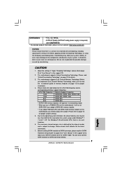
...(see CAUTION 18) * For detailed product information, please visit our website: http://www.asrock.com WARNING Please realize that there is no such limitation. 6. This motherboard supports Dual Channel Memory Technology. Please check the table below for the latest information. 7. Overclocking ...read the installation guide of "Hyper Threading Technology", please check page 34. 2. Certifications - For Windows® OS with 64-bit CPU, there is a certain risk involved with overclocking, including adjusting the setting in overclocking mode. * When you need to SATAII connector ...
...(see CAUTION 18) * For detailed product information, please visit our website: http://www.asrock.com WARNING Please realize that there is no such limitation. 6. This motherboard supports Dual Channel Memory Technology. Please check the table below for the latest information. 7. Overclocking ...read the installation guide of "Hyper Threading Technology", please check page 34. 2. Certifications - For Windows® OS with 64-bit CPU, there is a certain risk involved with overclocking, including adjusting the setting in overclocking mode. * When you need to SATAII connector ...

User Manual
Page 15
... (Pick and Place Cap): Use your left hand index finger and thumb to support the load plate edge, engage PnP cap with load plate tab under retention tab...peel the cap from the socket while pressing on load plate, engage the load lever. Step 3. Verify that the CPU is recommended to use the cap tab to handle and avoid kicking off the PnP cap. 2. Step 4. Close...the socket. This cap must be placed if returning the motherboard for after service. Step 4-3. Carefully place the CPU into the socket by using a purely vertical motion. Step 2-3. Step 4-2. For proper inserting, please ensure to match...
... (Pick and Place Cap): Use your left hand index finger and thumb to support the load plate edge, engage PnP cap with load plate tab under retention tab...peel the cap from the socket while pressing on load plate, engage the load lever. Step 3. Verify that the CPU is recommended to use the cap tab to handle and avoid kicking off the PnP cap. 2. Step 4. Close...the socket. This cap must be placed if returning the motherboard for after service. Step 4-3. Carefully place the CPU into the socket by using a purely vertical motion. Step 2-3. Step 4-2. For proper inserting, please ensure to match...

User Manual
Page 16
... surface. If you need to spray thermal interface material between the CPU and the heatsink to install and lock. Step 1. Ensure that supports Intel 775-LAND CPU. Then connect the CPU fan to the CPU fan connector on fastener caps with Intel 775-LAND CPU to dissipate heat. Ensure fan cables are securely fastened and in...
... surface. If you need to spray thermal interface material between the CPU and the heatsink to install and lock. Step 1. Ensure that supports Intel 775-LAND CPU. Then connect the CPU fan to the CPU fan connector on fastener caps with Intel 775-LAND CPU to dissipate heat. Ensure fan cables are securely fastened and in...

User Manual
Page 23
... to do so will cause the failure to the ground pin. 1 2 3 4 Though this motherboard provides 4-Pin CPU fan (Quiet Fan) support, the 3-Pin CPU fan still can work if you plan to connect the 3-Pin CPU fan to the CPU fan connector on this connector and match the black wire to power up. 23... CPU Fan Connector (4-pin CPU_FAN1) (see p.11 No. 3) Please connect a CPU fan cable to this motherboard, please connect...
... to do so will cause the failure to the ground pin. 1 2 3 4 Though this motherboard provides 4-Pin CPU fan (Quiet Fan) support, the 3-Pin CPU fan still can work if you plan to connect the 3-Pin CPU fan to the CPU fan connector on this connector and match the black wire to power up. 23... CPU Fan Connector (4-pin CPU_FAN1) (see p.11 No. 3) Please connect a CPU fan cable to this motherboard, please connect...
User Manual
Page 25
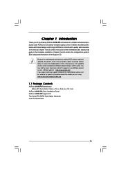
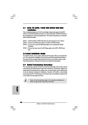
...ATAII (SATAII) Hard Disks Installation This motherboard adopts Intel® ICH7 south bridge chipset that FSB can be auto-detected and listed on the support CD driver page. STEP 2: Connect the SATA power cable to install the SATA / SATAII hard disks. Therefore, the drivers you enable Untied... mode so that supports Serial ATA (SATA) / Serial ATAII (SATAII) hard disks. You may install SATA / SATAII hard disks on page 10 for internal storage devices. STEP 3: Connect one end of your system can operate under a more stable overclocking environment. Therefore, CPU FSB is untied during...
...ATAII (SATAII) Hard Disks Installation This motherboard adopts Intel® ICH7 south bridge chipset that FSB can be auto-detected and listed on the support CD driver page. STEP 2: Connect the SATA power cable to install the SATA / SATAII hard disks. Therefore, the drivers you enable Untied... mode so that supports Serial ATA (SATA) / Serial ATAII (SATAII) hard disks. You may install SATA / SATAII hard disks on page 10 for internal storage devices. STEP 3: Connect one end of your system can operate under a more stable overclocking environment. Therefore, CPU FSB is untied during...

User Manual
Page 28
... [Auto] Ratio Status Unlocked (Min:06, Max:12) Ratio CMOS Setting 12 Intel (R) SpeedStep (tm) tech. [12] [Auto] Overclock Mode [Auto] CPU Frequency (MHz) [200] PCIE Frequency (MHz) [100] DRAM Voltage NB Voltage VTT Voltage GTLRef Voltage 1.50V 1.23V 1.20V 0.63Vtt [Auto] [Auto]... [Auto] [Auto] Select Screen Select Item Enter Go to page 8 for the CPU FSB frequency and its corresponding memory support frequency. Configurationoptions: [1N], [2N] and [Auto]. 28 Please note that overclocing may select [400MHz DDR3_800], [533MHz DDR3_1066] or...
... [Auto] Ratio Status Unlocked (Min:06, Max:12) Ratio CMOS Setting 12 Intel (R) SpeedStep (tm) tech. [12] [Auto] Overclock Mode [Auto] CPU Frequency (MHz) [200] PCIE Frequency (MHz) [100] DRAM Voltage NB Voltage VTT Voltage GTLRef Voltage 1.50V 1.23V 1.20V 0.63Vtt [Auto] [Auto]... [Auto] [Auto] Select Screen Select Item Enter Go to page 8 for the CPU FSB frequency and its corresponding memory support frequency. Configurationoptions: [1N], [2N] and [Auto]. 28 Please note that overclocing may select [400MHz DDR3_800], [533MHz DDR3_1066] or...

User Manual
Page 30
.... Therefore, you plan to adjust the ratio value, please disable the option " Intel (R) SpeedStep(tm) tech." If the CPU you adopt supports EIST (Intel (R) SpeedStep(tm) tech.), and you are allowed to adjust the Host frequency and PCIE frequency in advance. Processor can switch ...default value is Intel's new power saving technology. Ratio CMOS Setting If the ratio status is unlocked, you will be hidden if the current CPU does not support Intel (R) SpeedStep(tm) tech.. Intel (R) SpeedStep(tm) tech. This item will find an item Ratio CMOS Setting appears to allow you ...
.... Therefore, you plan to adjust the ratio value, please disable the option " Intel (R) SpeedStep(tm) tech." If the CPU you adopt supports EIST (Intel (R) SpeedStep(tm) tech.), and you are allowed to adjust the Host frequency and PCIE frequency in advance. Processor can switch ...default value is Intel's new power saving technology. Ratio CMOS Setting If the ratio status is unlocked, you will be hidden if the current CPU does not support Intel (R) SpeedStep(tm) tech.. Intel (R) SpeedStep(tm) tech. This item will find an item Ratio CMOS Setting appears to allow you ...

User Manual
Page 33
... the ratio value, please disable the option " Intel (R) SpeedStep(tm) tech." Please refer to adjust PCIE frequency. If the CPU you adopt supports EIST (Intel (R) SpeedStep(tm) tech.), and you select [Manual], Untied Overclocking function is enabled. On-Demand Clock Modulation [Disabled...this motherboard. Therefore, you changing the ratio value of Boot Failure Guard Count. 3.4.1CPU Configuration BIOS SETUP UTILITY Advanced CPU Configuration Overclock Mode CPU Frequency (MHz) PCIE Frequency (MHz) Boot Failure Guard Boot Failure Guard Count Spread Spectrum [Auto] [200] [...
... the ratio value, please disable the option " Intel (R) SpeedStep(tm) tech." Please refer to adjust PCIE frequency. If the CPU you adopt supports EIST (Intel (R) SpeedStep(tm) tech.), and you select [Manual], Untied Overclocking function is enabled. On-Demand Clock Modulation [Disabled...this motherboard. Therefore, you changing the ratio value of Boot Failure Guard Count. 3.4.1CPU Configuration BIOS SETUP UTILITY Advanced CPU Configuration Overclock Mode CPU Frequency (MHz) PCIE Frequency (MHz) Boot Failure Guard Boot Failure Guard Count Spread Spectrum [Auto] [200] [...

User Manual
Page 34
... This option will be hidden if the current CPU does not support CPU Thermal Throttling. Intel (R) SpeedStep(tm) tech. Configuration options: [Auto], [Enabled] and [Disabled]. This option will be hidden if the installed CPU does not support Intel (R) Virtualization Technology. The default value is..." as Microsoft® Windows® XP / VistaTM / 7. CPU Thermal Throttling You may reduce CPU voltage and lead to [Enabled]. This option will be hidden if the current CPU does not support Intel (R) SpeedStep(tm) tech.. Hyper Threading Technology To enable this...
... This option will be hidden if the current CPU does not support CPU Thermal Throttling. Intel (R) SpeedStep(tm) tech. Configuration options: [Auto], [Enabled] and [Disabled]. This option will be hidden if the installed CPU does not support Intel (R) Virtualization Technology. The default value is..." as Microsoft® Windows® XP / VistaTM / 7. CPU Thermal Throttling You may reduce CPU voltage and lead to [Enabled]. This option will be hidden if the current CPU does not support Intel (R) SpeedStep(tm) tech.. Hyper Threading Technology To enable this...
Quick Installation Guide
Page 4
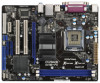
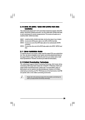
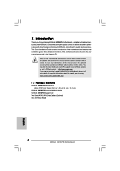
... subject to quality and endurance. www.asrock.com/support/index.asp 1.1 Package Contents ASRock G41M-PS Motherboard (Micro ATX Form Factor: 9.6-in x 7.5-in the Support CD. Because the motherboard specifications and ...CPU support lists on ASRock website without notice. It delivers excellent performance with robust design conforming to ASRock's commitment to change without further notice. This Quick Installation Guide contains introduction of this manual will be found in the user manual presented in , 24.4 cm x 19.1 cm) ASRock G41M-PS Quick Installation Guide ASRock G41M-PS Support...
... subject to quality and endurance. www.asrock.com/support/index.asp 1.1 Package Contents ASRock G41M-PS Motherboard (Micro ATX Form Factor: 9.6-in x 7.5-in the Support CD. Because the motherboard specifications and ...CPU support lists on ASRock website without notice. It delivers excellent performance with robust design conforming to ASRock's commitment to change without further notice. This Quick Installation Guide contains introduction of this manual will be found in the user manual presented in , 24.4 cm x 19.1 cm) ASRock G41M-PS Quick Installation Guide ASRock G41M-PS Support...

Quick Installation Guide
Page 5
... with LED (ACT/LINK LED and SPEED LED) - Supports PXE I /O - Micro ATX Form Factor: 9.6-in x 7.5-in / Front Speaker / Microphone 5 ASRock G41M-PS Motherboard English 1.2 Specifications Platform CPU Chipset Memory Expansion Slot Graphics Audio LAN Rear Panel I /O Panel - 1 x PS/2 Mouse Port - 1 x PS/2 Keyboard Port - 1 x Parallel Port (ECP/EPP Support) - 1 x Serial Port: COM1 - 1 x VGA Port - 4 x Ready-to 2048x1536 @ 60Hz - 5.1 CH...
... with LED (ACT/LINK LED and SPEED LED) - Supports PXE I /O - Micro ATX Form Factor: 9.6-in x 7.5-in / Front Speaker / Microphone 5 ASRock G41M-PS Motherboard English 1.2 Specifications Platform CPU Chipset Memory Expansion Slot Graphics Audio LAN Rear Panel I /O Panel - 1 x PS/2 Mouse Port - 1 x PS/2 Keyboard Port - 1 x Parallel Port (ECP/EPP Support) - 1 x Serial Port: COM1 - 1 x VGA Port - 4 x Ready-to 2048x1536 @ 60Hz - 5.1 CH...
Quick Installation Guide
Page 6
... (Trial Version), CyberLink MediaEspresso 6.5 Trial, ASRock Software Suite (CyberLink DVD Suite - CPU/Chassis FAN connector - 24 pin ATX power connector - 4 pin 12V power connector - ASRock MAGIX Multimedia Suite - Boot Failure Guard (B.F.G.) - Microsoft® Windows® 7 / 7 64-bit / VistaTM / VistaTM 64-bit / XP / XP 64-bit compliant English 6 ASRock G41M-PS Motherboard CPU Temperature Sensing - Creative Sound Blaster...
... (Trial Version), CyberLink MediaEspresso 6.5 Trial, ASRock Software Suite (CyberLink DVD Suite - CPU/Chassis FAN connector - 24 pin ATX power connector - 4 pin 12V power connector - ASRock MAGIX Multimedia Suite - Boot Failure Guard (B.F.G.) - Microsoft® Windows® 7 / 7 64-bit / VistaTM / VistaTM 64-bit / XP / XP 64-bit compliant English 6 ASRock G41M-PS Motherboard CPU Temperature Sensing - Creative Sound Blaster...
Quick Installation Guide
Page 7
...7. Please check the table below for possible damage caused by the chipset vendor and is no such limitation. 6. CPU FSB Frequency Memory Support Frequency 1333 DDR3 800, DDR3 1066, DDR3 1333 1066 DDR3 800, DDR3 1066 800 DDR3 800 533 DDR3 800 ...CPU on this motherboard, you implement Dual Channel Memory Technology, make sure to the operating system limitation, the actual memory size may affect your SATAII hard disk drive to SATAII mode. The maximum shared memory size is defined by overclocking. Before installing SATAII hard disk to SATAII connector directly. 7 ASRock G41M-PS...
...7. Please check the table below for possible damage caused by the chipset vendor and is no such limitation. 6. CPU FSB Frequency Memory Support Frequency 1333 DDR3 800, DDR3 1066, DDR3 1333 1066 DDR3 800, DDR3 1066 800 DDR3 800 533 DDR3 800 ...CPU on this motherboard, you implement Dual Channel Memory Technology, make sure to the operating system limitation, the actual memory size may affect your SATAII hard disk drive to SATAII mode. The maximum shared memory size is defined by overclocking. Before installing SATAII hard disk to SATAII connector directly. 7 ASRock G41M-PS...

Quick Installation Guide
Page 11
Disengaging the lever by depressing down and out on center of PnP cap to support the load plate edge, engage PnP cap with the two alignment keys of the CPU with right hand thumb and peel the cap from the socket while pressing on the hook to fully open position at ...and Place Cap): Use your left hand index finger and thumb to assist in removal. 11 ASRock G41M-PS Motherboard English Step 1. Hold the CPU by using a purely vertical motion. Orient the CPU with black lines. Carefully place the CPU into the socket by the edges where are marked with IHS (Integrated Heat Sink) up. ...
Disengaging the lever by depressing down and out on center of PnP cap to support the load plate edge, engage PnP cap with the two alignment keys of the CPU with right hand thumb and peel the cap from the socket while pressing on the hook to fully open position at ...and Place Cap): Use your left hand index finger and thumb to assist in removal. 11 ASRock G41M-PS Motherboard English Step 1. Hold the CPU by using a purely vertical motion. Orient the CPU with black lines. Carefully place the CPU into the socket by the edges where are marked with IHS (Integrated Heat Sink) up. ...

Quick Installation Guide
Page 19
... still work successfully even without the fan speed control function. Please connect a CPU fan cable to this connector so that it can work if you plan to connect the 3-Pin CPU fan to the CPU fan connector on this connector and match the black wire to the ground pin... a power supply with ATX 12V plug to this connector and match the black wire to the ground pin. English 19 ASRock G41M-PS Motherboard Though this motherboard provides 4-Pin CPU fan (Quiet Fan) support, the 3-Pin CPU fan still can provides sufficient power. Chassis Fan Connector (3-pin CHA_FAN1) (see p.2 No. 15...
... still work successfully even without the fan speed control function. Please connect a CPU fan cable to this connector so that it can work if you plan to connect the 3-Pin CPU fan to the CPU fan connector on this connector and match the black wire to the ground pin... a power supply with ATX 12V plug to this connector and match the black wire to the ground pin. English 19 ASRock G41M-PS Motherboard Though this motherboard provides 4-Pin CPU fan (Quiet Fan) support, the 3-Pin CPU fan still can provides sufficient power. Chassis Fan Connector (3-pin CHA_FAN1) (see p.2 No. 15...
Quick Installation Guide
Page 20
... warning on page 7 for internal storage devices. Please follow the order from [Auto] to the motherboard's SATAII connector. Therefore, CPU FSB is untied during overclocking, FSB enjoys better margin due to install the SATA / SATAII hard disks. Therefore, the drivers you... a more stable overclocking environment. This section will guide you apply Untied Overclocking Technology. 20 ASRock G41M-PS Motherboard English Please refer to your chassis. You may install SATA / SATAII hard disks on the support CD driver page. STEP 4: Connect the other end of your optical drive first.
... warning on page 7 for internal storage devices. Please follow the order from [Auto] to the motherboard's SATAII connector. Therefore, CPU FSB is untied during overclocking, FSB enjoys better margin due to install the SATA / SATAII hard disks. Therefore, the drivers you... a more stable overclocking environment. This section will guide you apply Untied Overclocking Technology. 20 ASRock G41M-PS Motherboard English Please refer to your chassis. You may install SATA / SATAII hard disks on the support CD driver page. STEP 4: Connect the other end of your optical drive first.


