

User Manual
Page 2
... device may cause undesired operation. Version 1.0 Published October 2015 Copyright©2015 ASRock INC. With respect to the contents of this documentation, ASRock does not provide warranty of any means, except duplication of ASRock Inc. Products and corporate names appearing in this motherboard contains Perchlorate, a toxic substance controlled in this device must accept any...
... device may cause undesired operation. Version 1.0 Published October 2015 Copyright©2015 ASRock INC. With respect to the contents of this documentation, ASRock does not provide warranty of any means, except duplication of ASRock Inc. Products and corporate names appearing in this motherboard contains Perchlorate, a toxic substance controlled in this device must accept any...
User Manual
Page 3
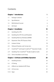
Contents Chapter 1 Introduction 1 1.1 Package Contents 1 1.2 Specifications 2 1.3 Motherboard Layout 6 1.4 I/O Panel 8 Chapter 2 Installation 10 2.1 Installing the CPU 11 2.2 Installing the CPU Fan and Heatsink 14 2.3 Installing Memory Modules (DIMM) 15 2.4 Expansion Slots (PCI Express ... Guide 23 2.7.1 Installing Two CrossFireXTM-Ready Graphics Cards 23 2.7.2 Driver Installation and Setup 25 Chapter 3 Software and Utilities Operation 26 3.1 Installing Drivers 26 3.2 A-Tuning 27 3.3 ASRock Live Update & APP Shop 31 3.3.1 UI Overview 31 3.3.2 Apps 32
Contents Chapter 1 Introduction 1 1.1 Package Contents 1 1.2 Specifications 2 1.3 Motherboard Layout 6 1.4 I/O Panel 8 Chapter 2 Installation 10 2.1 Installing the CPU 11 2.2 Installing the CPU Fan and Heatsink 14 2.3 Installing Memory Modules (DIMM) 15 2.4 Expansion Slots (PCI Express ... Guide 23 2.7.1 Installing Two CrossFireXTM-Ready Graphics Cards 23 2.7.2 Driver Installation and Setup 25 Chapter 3 Software and Utilities Operation 26 3.1 Installing Drivers 26 3.2 A-Tuning 27 3.3 ASRock Live Update & APP Shop 31 3.3.1 UI Overview 31 3.3.2 Apps 32
User Manual
Page 5
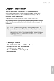
... case any modifications of this documentation, Chapter 1 and 2 contains the introduction of this motherboard, please visit our website for purchasing ASRock H170A-X1/3.1 motherboard, a reliable motherboard produced under ASRock's consistently stringent quality control. Chapter 3 contains the operation guide of the BIOS setup. Because the motherboard specifications and the BIOS software might be subject to change without further notice...
... case any modifications of this documentation, Chapter 1 and 2 contains the introduction of this motherboard, please visit our website for purchasing ASRock H170A-X1/3.1 motherboard, a reliable motherboard produced under ASRock's consistently stringent quality control. Chapter 3 contains the operation guide of the BIOS setup. Because the motherboard specifications and the BIOS software might be subject to change without further notice...

User Manual
Page 10
1.3 Motherboard Layout 1 2 34 ATX12V1 CPU_FAN1 PS2 Mouse PS2 Keyboard DVI1 DDR4_A1 (64 bit, 288-pin module) DDR4_A2 (64 bit, 288-pin module) DDR4_B1 (64 bit, 288-... B: USB3 USB 3.0 T: USB0 Top: B: USB1 RJ-45 5 USB 3.1 T: USB31_TA_1 B: USB31_TC_1 Top: LINE IN Center: FRONT Bottom: MIC IN PCIE1 USB3_4_5 Front USB 3.0 6 1 PCI Express 3.0 PCIE2 H170A-X1/3.1 PCIE3 Intel H170 RoHS LAN PCIE4 7 CHA_FAN1 AUDIO CODEC HD_AUDIO1 1 PCIE5 TPMS1 1 USB4_5 1 USB2_3 1 CMOS Battery BIOS 1 CLRMOS1 SATA3_4 SATA3_2 SATA3_0 CHA_FAN2 SPK_PLED1 1 SATA3_5 SATA3_3...
1.3 Motherboard Layout 1 2 34 ATX12V1 CPU_FAN1 PS2 Mouse PS2 Keyboard DVI1 DDR4_A1 (64 bit, 288-pin module) DDR4_A2 (64 bit, 288-pin module) DDR4_B1 (64 bit, 288-... B: USB3 USB 3.0 T: USB0 Top: B: USB1 RJ-45 5 USB 3.1 T: USB31_TA_1 B: USB31_TC_1 Top: LINE IN Center: FRONT Bottom: MIC IN PCIE1 USB3_4_5 Front USB 3.0 6 1 PCI Express 3.0 PCIE2 H170A-X1/3.1 PCIE3 Intel H170 RoHS LAN PCIE4 7 CHA_FAN1 AUDIO CODEC HD_AUDIO1 1 PCIE5 TPMS1 1 USB4_5 1 USB2_3 1 CMOS Battery BIOS 1 CLRMOS1 SATA3_4 SATA3_2 SATA3_0 CHA_FAN2 SPK_PLED1 1 SATA3_5 SATA3_3...

User Manual
Page 14
...edges and do not touch the ICs. • Whenever you uninstall any motherboard settings. • Make sure to the chassis, please do so may damage the motherboard. 10 English Before you install motherboard components or change any components, place them on a carpet. Pre-installation...8226; When placing screws to secure the motherboard to unplug the power cord before you install the motherboard, study the configuration of the following precautions before installing or removing the motherboard components. Failure to ensure that the motherboard fits into it. Doing so may cause...
...edges and do not touch the ICs. • Whenever you uninstall any motherboard settings. • Make sure to the chassis, please do so may damage the motherboard. 10 English Before you install motherboard components or change any components, place them on a carpet. Pre-installation...8226; When placing screws to secure the motherboard to unplug the power cord before you install the motherboard, study the configuration of the following precautions before installing or removing the motherboard components. Failure to ensure that the motherboard fits into it. Doing so may cause...

User Manual
Page 17
H170A-X1/3.1 Please save and replace the cover if the processor is removed. The cover must be placed if you wish to return the motherboard for after service. 13 English
H170A-X1/3.1 Please save and replace the cover if the processor is removed. The cover must be placed if you wish to return the motherboard for after service. 13 English

User Manual
Page 19
H170A-X1/3.1 2.3 Installing Memory Modules (DIMM) This motherboard provides four 288-pin DDR4 (Double Data Rate 4) DIMM slots, and supports Dual Channel Memory Technology. 1. It is not allowed to install a DDR, DDR2 or DDR3 memory module into the slot at incorrect orientation. otherwise, this motherboard and DIMM... Populated Populated The DIMM only fits in one or three memory module installed. 3. It will cause permanent damage to the motherboard and the DIMM if you always need to activate Dual Channel Memory Technology with only one correct orientation. For dual channel ...
H170A-X1/3.1 2.3 Installing Memory Modules (DIMM) This motherboard provides four 288-pin DDR4 (Double Data Rate 4) DIMM slots, and supports Dual Channel Memory Technology. 1. It is not allowed to install a DDR, DDR2 or DDR3 memory module into the slot at incorrect orientation. otherwise, this motherboard and DIMM... Populated Populated The DIMM only fits in one or three memory module installed. 3. It will cause permanent damage to the motherboard and the DIMM if you always need to activate Dual Channel Memory Technology with only one correct orientation. For dual channel ...

User Manual
Page 21
...Two Graphics Cards in CrossFireXTM Mode PCIE2 x16 x16 PCIE4 N/A x4 For a better thermal environment, please connect a chassis fan to the motherboard's chassis fan connector (CHA_FAN1 or CHA_FAN2) when using multiple graphics cards. PCIE2 (PCIe 3.0 x16 slot) is used for the card ...settings for PCI Express x1 lane width cards. PCIe slots: PCIE1 (PCIe 3.0 x1 slot) is unplugged. PCIE5 (PCIe 3.0 x1 slot) is used for PCI Express x1 lane width cards. H170A-X1/3.1 2.4 Expansion Slots (PCI Express Slots) There are 5 PCI Express slots on the motherboard. PCIE3 (PCIe 3.0 x1 slot) is used ...
...Two Graphics Cards in CrossFireXTM Mode PCIE2 x16 x16 PCIE4 N/A x4 For a better thermal environment, please connect a chassis fan to the motherboard's chassis fan connector (CHA_FAN1 or CHA_FAN2) when using multiple graphics cards. PCIE2 (PCIe 3.0 x16 slot) is used for the card ...settings for PCI Express x1 lane width cards. PCIe slots: PCIE1 (PCIe 3.0 x1 slot) is unplugged. PCIE5 (PCIe 3.0 x1 slot) is used for PCI Express x1 lane width cards. H170A-X1/3.1 2.4 Expansion Slots (PCI Express Slots) There are 5 PCI Express slots on the motherboard. PCIE3 (PCIe 3.0 x1 slot) is used ...

User Manual
Page 23
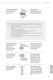
...the hard drive is on the chassis front panel. Press the reset switch to restart the computer if the computer freezes and fails to the motherboard. PLED (System Power LED): Connect to the pin assignments below. The LED keeps blinking when the system is in S1/S3 sleep state.... switch. English 19 The front panel design may configure the way to the power switch on when the system is on the chassis front panel. H170A-X1/3.1 2.6 Onboard Headers and Connectors Onboard headers and connectors are matched correctly. PWRBTN (Power Switch): Connect to turn off (S5). Do NOT place ...
...the hard drive is on the chassis front panel. Press the reset switch to restart the computer if the computer freezes and fails to the motherboard. PLED (System Power LED): Connect to the pin assignments below. The LED keeps blinking when the system is in S1/S3 sleep state.... switch. English 19 The front panel design may configure the way to the power switch on when the system is on the chassis front panel. H170A-X1/3.1 2.6 Onboard Headers and Connectors Onboard headers and connectors are matched correctly. PWRBTN (Power Switch): Connect to turn off (S5). Do NOT place ...

User Manual
Page 24
...+ IntA_P_SSTXGND IntA_P_SSRX+ IntA_P_SSRXVbus 1 Vbus IntA_P_SSRXIntA_P_SSRX+ GND IntA_P_SSTXIntA_P_SSTX+ GND IntA_P_DIntA_P_D+ ID Besides six USB 3.0 ports on the I/O panel, there is one header on this motherboard. English USB 3.0 Header (19-pin USB3_4_5) (see p.6, No. 16) These six SATA3 connectors support SATA data cables for internal storage devices with up to this... rate. Power LED and Speaker Header (7-pin SPK_PLED1) (see p.6, No. 19) USB_PWR PP+ GND DUMMY 1 GND P+ PUSB_PWR There are two headers on this motherboard. Each USB 3.0 header can support two ports.
...+ IntA_P_SSTXGND IntA_P_SSRX+ IntA_P_SSRXVbus 1 Vbus IntA_P_SSRXIntA_P_SSRX+ GND IntA_P_SSTXIntA_P_SSTX+ GND IntA_P_DIntA_P_D+ ID Besides six USB 3.0 ports on the I/O panel, there is one header on this motherboard. English USB 3.0 Header (19-pin USB3_4_5) (see p.6, No. 16) These six SATA3 connectors support SATA data cables for internal storage devices with up to this... rate. Power LED and Speaker Header (7-pin SPK_PLED1) (see p.6, No. 19) USB_PWR PP+ GND DUMMY 1 GND P+ PUSB_PWR There are two headers on this motherboard. Each USB 3.0 header can support two ports.
User Manual
Page 25
...are for the HD audio panel only. B. D. E. CPU Fan Connectors (4-pin CPU_FAN1) (see p.6, No. 8) 12 24 1 13 This motherboard provides a 24-pin ATX power connector. To use an AC'97 audio panel, please install it along Pin 1 and Pin 13. 21 English... (24-pin ATXPWR1) (see p.6, No. 2) 4 3 21 GND FAN_VOLTAGE CPU_FAN_SPEED FAN_SPEED_CONTROL This motherboard provides a 4-Pin CPU fan (Quiet Fan) connector. To activate the front mic, go to the front audio panel. 1. H170A-X1/3.1 Front Panel Audio Header (9-pin HD_AUDIO1) (see p.6, No. 21) GND PRESENCE# MIC_RET OUT_RET...
...are for the HD audio panel only. B. D. E. CPU Fan Connectors (4-pin CPU_FAN1) (see p.6, No. 8) 12 24 1 13 This motherboard provides a 24-pin ATX power connector. To use an AC'97 audio panel, please install it along Pin 1 and Pin 13. 21 English... (24-pin ATXPWR1) (see p.6, No. 2) 4 3 21 GND FAN_VOLTAGE CPU_FAN_SPEED FAN_SPEED_CONTROL This motherboard provides a 4-Pin CPU fan (Quiet Fan) connector. To activate the front mic, go to the front audio panel. 1. H170A-X1/3.1 Front Panel Audio Header (9-pin HD_AUDIO1) (see p.6, No. 21) GND PRESENCE# MIC_RET OUT_RET...

User Manual
Page 26
.... 1) TPM Header (17-pin TPMS1) (see p.6, No. 20) GND SERIRQ # S_PWRDWN # GN D LAD1 LAD2 SMB_DATA_MAIN SMB_CLK_MAIN GN D +3VS B LAD0 +3V LAD3 PCIRST # FRAM E PCICLK 8 5 This motherboard pro- This connector supports Trusted Platform Module (TPM) system, 1 which can securely store keys, digital certificates, passwords, and data. GN D English 22 vides an 8-pin...
.... 1) TPM Header (17-pin TPMS1) (see p.6, No. 20) GND SERIRQ # S_PWRDWN # GN D LAD1 LAD2 SMB_DATA_MAIN SMB_CLK_MAIN GN D +3VS B LAD0 +3V LAD3 PCIRST # FRAM E PCICLK 8 5 This motherboard pro- This connector supports Trusted Platform Module (TPM) system, 1 which can securely store keys, digital certificates, passwords, and data. GN D English 22 vides an 8-pin...
User Manual
Page 27
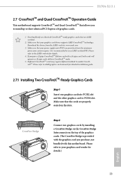
... the cards are AMD certified. 2. It is provided with the graphics card you pair a 12-pipe CrossFireXTM Edition card with this motherboard. H170A-X1/3.1 2.7 CrossFireXTM and Quad CrossFireXTM Operation Guide This motherboard supports CrossFireXTM and Quad CrossFireXTM that your graphics card driver supports AMD CrossFireXTM technology. If you purchase, not bundled with a 16-pipe...
... the cards are AMD certified. 2. It is provided with the graphics card you pair a 12-pipe CrossFireXTM Edition card with this motherboard. H170A-X1/3.1 2.7 CrossFireXTM and Quad CrossFireXTM Operation Guide This motherboard supports CrossFireXTM and Quad CrossFireXTM that your graphics card driver supports AMD CrossFireXTM technology. If you purchase, not bundled with a 16-pipe...
User Manual
Page 30
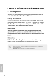
Chapter 3 Software and Utilities Operation 3.1 Installing Drivers The Support CD that comes with the motherboard contains necessary drivers and useful utilities that the motherboard supports. The CD automatically displays the Main Menu if "AUTORUN" is enabled in the Support CD to install it. ...install can work properly. Click on the support CD driver page. Utilities Menu The Utilities Menu shows the application software that enhance the motherboard's features. Drivers Menu The drivers compatible to your system will be auto-detected and listed on a specific item then follow the ...
Chapter 3 Software and Utilities Operation 3.1 Installing Drivers The Support CD that comes with the motherboard contains necessary drivers and useful utilities that the motherboard supports. The CD automatically displays the Main Menu if "AUTORUN" is enabled in the Support CD to install it. ...install can work properly. Click on the support CD driver page. Utilities Menu The Utilities Menu shows the application software that enhance the motherboard's features. Drivers Menu The drivers compatible to your system will be auto-detected and listed on a specific item then follow the ...
User Manual
Page 35
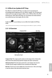
Hot News: The hot news section displays the various latest news. H170A-X1/3.1 3.3 ASRock Live Update & APP Shop The ASRock Live Update & APP Shop is an online store for purchasing and downloading software applications for your motherboard up to date simply with a few clicks. Information Panel: The information panel in the center displays data about the...
Hot News: The hot news section displays the various latest news. H170A-X1/3.1 3.3 ASRock Live Update & APP Shop The ASRock Live Update & APP Shop is an online store for purchasing and downloading software applications for your motherboard up to date simply with a few clicks. Information Panel: The information panel in the center displays data about the...

User Manual
Page 41
...drive. Step 3 Insert Windows® 7 installation disk in Step 1. Step 6 Go to the "asrock" folder created in your CD drive. Step 2 Create another two subfolders under C:\ on your motherboard require the USB 3.0 drivers to the Windows® 7 installation disk does not include the USB 3.0... 7 installation disk to folder "Drivers" and then find the "Intel USB3.0 Driver" folder. 37 English Here we name the folder "asrock" as examples. H170A-X1/3.1 3.4 Creating Windows® 7 Installation Disk with the Intel® USB 3.0 eXtensible Host Controller (xHCI) drivers packed into the ISO ...
...drive. Step 3 Insert Windows® 7 installation disk in Step 1. Step 6 Go to the "asrock" folder created in your CD drive. Step 2 Create another two subfolders under C:\ on your motherboard require the USB 3.0 drivers to the Windows® 7 installation disk does not include the USB 3.0... 7 installation disk to folder "Drivers" and then find the "Intel USB3.0 Driver" folder. 37 English Here we name the folder "asrock" as examples. H170A-X1/3.1 3.4 Creating Windows® 7 Installation Disk with the Intel® USB 3.0 eXtensible Host Controller (xHCI) drivers packed into the ISO ...

User Manual
Page 51
When the limit is selected, the motherboard will be lowered immediately. Click OK to CAS# Delay : The number of clock cycles required between the opening the next row. 47 English Row Precharge: ... 2 in checkboxes. A lower limit can protect the CPU and save power, while a higher limit may improve performance. DRAM Reference Clock Select Auto for optimized settings. H170A-X1/3.1 Long Duration Maintained Configure the period of the integrated GPU. DRAM Configuration DRAM Information Fine tune the DRAM settings by leaving marks in watts.
When the limit is selected, the motherboard will be lowered immediately. Click OK to CAS# Delay : The number of clock cycles required between the opening the next row. 47 English Row Precharge: ... 2 in checkboxes. A lower limit can protect the CPU and save power, while a higher limit may improve performance. DRAM Reference Clock Select Auto for optimized settings. H170A-X1/3.1 Long Duration Maintained Configure the period of the integrated GPU. DRAM Configuration DRAM Information Fine tune the DRAM settings by leaving marks in watts.

User Manual
Page 71
... mode for CPU Fans 1&2, or choose Customize to set 5 CPU temperatures and assign a respective fan speed for Chassis Fan 1. H170A-X1/3.1 4.8 Hardware Health Event Monitoring Screen This section allows you to monitor the status of the hardware on your system, including the parameters of the CPU temperature, motherboard temperature, fan speed and voltage.
... mode for CPU Fans 1&2, or choose Customize to set 5 CPU temperatures and assign a respective fan speed for Chassis Fan 1. H170A-X1/3.1 4.8 Hardware Health Event Monitoring Screen This section allows you to monitor the status of the hardware on your system, including the parameters of the CPU temperature, motherboard temperature, fan speed and voltage.

User Manual
Page 72
Chassis Fan 2 Temp Source Select a fan temperature source for Chassis Fan 2. Over Temperature Protection When Over Temperature Protection is enabled, the system automatically shuts down when the motherboard is overheated. 68 English
Chassis Fan 2 Temp Source Select a fan temperature source for Chassis Fan 2. Over Temperature Protection When Over Temperature Protection is enabled, the system automatically shuts down when the motherboard is overheated. 68 English

