
User Manual
Page 3
...1.3 Motherboard Layout 5 1.4 I/O Panel 7 1.5 Block Diagram 8 Chapter 2 Installation 9 2.1 Installing the CPU 10 2.2 Installing the CPU Fan and Heatsink 13 2.3 Installing Memory Modules (DIMM) 14 2.4 Connecting the Front Panel Header 16 2.5 Installing the I/O Panel Shield 17 2.6 Installing the Motherboard 18 2.7 Installing SATA Drives 19 2.8 Installing a Graphics Card 21 2.9 Connecting Peripheral Devices 23 2.10 Connecting the Power Connectors 24 2.11 Power On 25 2.12 Jumpers Setup 26 2.13 Onboard Headers and Connectors 27 2.14 M.2 SSD Module Installation Guide...
...1.3 Motherboard Layout 5 1.4 I/O Panel 7 1.5 Block Diagram 8 Chapter 2 Installation 9 2.1 Installing the CPU 10 2.2 Installing the CPU Fan and Heatsink 13 2.3 Installing Memory Modules (DIMM) 14 2.4 Connecting the Front Panel Header 16 2.5 Installing the I/O Panel Shield 17 2.6 Installing the Motherboard 18 2.7 Installing SATA Drives 19 2.8 Installing a Graphics Card 21 2.9 Connecting Peripheral Devices 23 2.10 Connecting the Power Connectors 24 2.11 Power On 25 2.12 Jumpers Setup 26 2.13 Onboard Headers and Connectors 27 2.14 M.2 SSD Module Installation Guide...

User Manual
Page 4
... latest VGA cards and CPU support list on ASRock's website without notice. If you require technical support related to this documentation occur, the updated version will be updated, the content of this motherboard, please visit our website for specific information about the model you for M.2 Socket (Optional) 1 English In case any modifications of this documentation will be available on ASRock's website as well. Because the motherboard specifications and the BIOS software...
... latest VGA cards and CPU support list on ASRock's website without notice. If you require technical support related to this documentation occur, the updated version will be updated, the content of this motherboard, please visit our website for specific information about the model you for M.2 Socket (Optional) 1 English In case any modifications of this documentation will be available on ASRock's website as well. Because the motherboard specifications and the BIOS software...

User Manual
Page 5
... Memory Support List on ASRock's website for more information. (http://www.asrock.com/) Expansion Slot CPU: • 1 x PCIe 4.0 x16 Slot (PCIE1), supports x16 mode* Chipset: • 1 x PCIe 3.0 x1 Slot (PCIE2)* * Supports NVMe SSD as boot disks Graphics • Intel® UHD Graphics Built-in Visuals and the VGA outputs can be supported only with DSC (compressed), supports HDCP 2.3 and max. 1.2 Specifications Platform • Micro ATX Form Factor CPU • Supports 13th Gen & 12th Gen Intel® CoreTM Processors...
... Memory Support List on ASRock's website for more information. (http://www.asrock.com/) Expansion Slot CPU: • 1 x PCIe 4.0 x16 Slot (PCIE1), supports x16 mode* Chipset: • 1 x PCIe 3.0 x1 Slot (PCIE2)* * Supports NVMe SSD as boot disks Graphics • Intel® UHD Graphics Built-in Visuals and the VGA outputs can be supported only with DSC (compressed), supports HDCP 2.3 and max. 1.2 Specifications Platform • Micro ATX Form Factor CPU • Supports 13th Gen & 12th Gen Intel® CoreTM Processors...

User Manual
Page 6
...4 x USB 2.0 Ports • 1 x RJ-45 LAN Port • HD Audio Jacks: Line in / Front Speaker / Microphone Storage Chipset: • 1 x Ultra M.2 Socket (M2_1, Key M), supports type 2242/2260/2280 PCIe Gen3x4 (32 Gb/s) mode* • 4 x SATA3 6.0 Gb/s Connectors * Supports NVMe SSD as boot disks Connector • 1 x SPI TPM Header • 1 x Chassis Intrusion and Speaker Header • 1 x Addressable LED Header* • 1 x CPU Fan Connector (4-pin)** • 1 x Chassis/Water Pump Fan Connector (4-pin) (Smart Fan Speed Control)*** • 1 x 24 pin ATX Power Connector • 1 x 8 pin...
...4 x USB 2.0 Ports • 1 x RJ-45 LAN Port • HD Audio Jacks: Line in / Front Speaker / Microphone Storage Chipset: • 1 x Ultra M.2 Socket (M2_1, Key M), supports type 2242/2260/2280 PCIe Gen3x4 (32 Gb/s) mode* • 4 x SATA3 6.0 Gb/s Connectors * Supports NVMe SSD as boot disks Connector • 1 x SPI TPM Header • 1 x Chassis Intrusion and Speaker Header • 1 x Addressable LED Header* • 1 x CPU Fan Connector (4-pin)** • 1 x Chassis/Water Pump Fan Connector (4-pin) (Smart Fan Speed Control)*** • 1 x 24 pin ATX Power Connector • 1 x 8 pin...

User Manual
Page 7
... auto detect if 3-pin or 4-pin fan is in use. • AMI UEFI Legal BIOS with GUI support • Microsoft® Windows® 10 64-bit / 11 64-bit • FCC, CE • ErP/EuP ready (ErP/EuP ready power supply is required) * For detailed product information, please visit our website: http://www.asrock.com Please realize that there is a certain risk involved with overclocking...
... auto detect if 3-pin or 4-pin fan is in use. • AMI UEFI Legal BIOS with GUI support • Microsoft® Windows® 10 64-bit / 11 64-bit • FCC, CE • ErP/EuP ready (ErP/EuP ready power supply is required) * For detailed product information, please visit our website: http://www.asrock.com Please realize that there is a certain risk involved with overclocking...

User Manual
Page 9
... 1 ATX 12V Power Connector (ATX12V1) 2 CPU Fan Connector (CPU_FAN1) 3 2 x 288-pin DDR5 DIMM Slots (DDR5_A1, DDR5_B1) 4 Chassis/Water Pump Fan Connector (CHA_FAN1/WP) 5 ATX Power Connector (ATXPWR1) 6 USB 3.2 Gen1 Header (USB3_2_3) 7 USB 2.0 Header (USB_5_6) 8 SATA3 Connector (SATA3_2) (Upper), SATA3 Connector (SATA3_3) (Lower) 9 SPI TPM Header (SPI_TPM_J1) 10 SATA3 Connector (SATA3_1) 11 SATA3 Connector (SATA3_0) 12 System Panel Header (PANEL1) 13 Chassis Intrusion and Speaker Header (SPK_CI1) 14 Clear CMOS Jumper (CLRMOS1) 15 Addressable LED Header (ADDR_LED1) 16 Front Panel Audio Header...
... 1 ATX 12V Power Connector (ATX12V1) 2 CPU Fan Connector (CPU_FAN1) 3 2 x 288-pin DDR5 DIMM Slots (DDR5_A1, DDR5_B1) 4 Chassis/Water Pump Fan Connector (CHA_FAN1/WP) 5 ATX Power Connector (ATXPWR1) 6 USB 3.2 Gen1 Header (USB3_2_3) 7 USB 2.0 Header (USB_5_6) 8 SATA3 Connector (SATA3_2) (Upper), SATA3 Connector (SATA3_3) (Lower) 9 SPI TPM Header (SPI_TPM_J1) 10 SATA3 Connector (SATA3_1) 11 SATA3 Connector (SATA3_0) 12 System Panel Header (PANEL1) 13 Chassis Intrusion and Speaker Header (SPK_CI1) 14 Clear CMOS Jumper (CLRMOS1) 15 Addressable LED Header (ADDR_LED1) 16 Front Panel Audio Header...

User Manual
Page 10
... (Pink)** 6 USB 2.0 Ports (USB_3_4) 10 9 7 6 5 8 No. ACT/LINK LED SPEED LED LAN Port Activity / Link LED Status Description Off Blinking On No Link Data Activity Link Speed LED Status Off Orange Green Description 10Mbps connection 100Mbps connection 1Gbps connection ** Function of the Audio Ports in 7.1-channel Configuration: Port Light Blue (Rear panel) Lime (Rear panel) Pink (Rear panel) Lime (Front panel) Function Rear Speaker Out Front Speaker Out Central /Subwoofer Speaker Out Side Speaker Out 7 English 1.4 I/O Panel H610M-HDV/M.2+ D5 3 1 2 4 12...
... (Pink)** 6 USB 2.0 Ports (USB_3_4) 10 9 7 6 5 8 No. ACT/LINK LED SPEED LED LAN Port Activity / Link LED Status Description Off Blinking On No Link Data Activity Link Speed LED Status Off Orange Green Description 10Mbps connection 100Mbps connection 1Gbps connection ** Function of the Audio Ports in 7.1-channel Configuration: Port Light Blue (Rear panel) Lime (Rear panel) Pink (Rear panel) Lime (Front panel) Function Rear Speaker Out Front Speaker Out Central /Subwoofer Speaker Out Side Speaker Out 7 English 1.4 I/O Panel H610M-HDV/M.2+ D5 3 1 2 4 12...

User Manual
Page 12
H610M-HDV/M.2+ D5 Chapter 2 Installation This is a Micro ATX form factor motherboard. Failure to ensure that comes with the components. • When placing screws to secure the motherboard to the chassis, please do so may damage the motherboard. 9 English Doing so may cause physical injuries and damages to motherboard components. • In order to avoid damage from static electricity to unplug the...
H610M-HDV/M.2+ D5 Chapter 2 Installation This is a Micro ATX form factor motherboard. Failure to ensure that comes with the components. • When placing screws to secure the motherboard to the chassis, please do so may damage the motherboard. 9 English Doing so may cause physical injuries and damages to motherboard components. • In order to avoid damage from static electricity to unplug the...

User Manual
Page 17
..., speed, size and chip-type) DDR5 DIMM pairs. 2. It is unable to install a DDR, DDR2, DDR3 or DDR4 memory module into the slot at incorrect orientation. 14 English The DIMM only fits in one memory module installed. 3. For dual channel configuration, you always need to the motherboard and the DIMM if you force the DIMM into a DDR5 slot; 2.3 Installing Memory Modules (DIMM) This motherboard provides two 288-pin...
..., speed, size and chip-type) DDR5 DIMM pairs. 2. It is unable to install a DDR, DDR2, DDR3 or DDR4 memory module into the slot at incorrect orientation. 14 English The DIMM only fits in one memory module installed. 3. For dual channel configuration, you always need to the motherboard and the DIMM if you force the DIMM into a DDR5 slot; 2.3 Installing Memory Modules (DIMM) This motherboard provides two 288-pin...

User Manual
Page 25
Please read the documentation of the expansion card and make sure that the power supply is switched off or the power cord is unplugged. Before installing an expansion card, please make necessary hardware settings for the card before you start the installation. PCIE2 (PCIe 3.0 x1 slot) is used for PCIe x16 lane width graphics cards. Expansion Slots (PCIe Slots) There are 2 PCI Express slots on the motherboard. PCIe slots: PCIE1 (PCIe 4.0 x16 slot) is used for PCIe x1 lane width cards. 22 English
Please read the documentation of the expansion card and make sure that the power supply is switched off or the power cord is unplugged. Before installing an expansion card, please make necessary hardware settings for the card before you start the installation. PCIE2 (PCIe 3.0 x1 slot) is used for PCIe x16 lane width graphics cards. Expansion Slots (PCIe Slots) There are 2 PCI Express slots on the motherboard. PCIe slots: PCIE1 (PCIe 4.0 x16 slot) is used for PCIe x1 lane width cards. 22 English
User Manual
Page 29
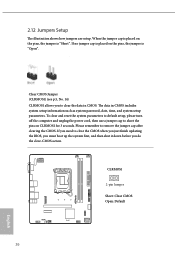
To clear and reset the system parameters to default setup, please turn off the computer and unplug the power cord, then use a jumper cap to clear the CMOS when you just finish updating the BIOS, you must boot up the system first, and then shut it down before you do the clear-CMOS action. If no jumper cap is placed on the pins, the jumper is "Open". If you...
To clear and reset the system parameters to default setup, please turn off the computer and unplug the power cord, then use a jumper cap to clear the CMOS when you just finish updating the BIOS, you must boot up the system first, and then shut it down before you do the clear-CMOS action. If no jumper cap is placed on the pins, the jumper is "Open". If you...

User Manual
Page 30
... may configure the way to the hard drive activity LED on the chassis front panel. You may differ by chassis. RESET (Reset Button): Connect to the motherboard. Do NOT place jumper caps over the headers and connectors will cause permanent damage to the reset button on the chassis front panel. A front panel module mainly consists of power button, reset button, power LED, hard drive activity LED, speaker and etc. PLED (System Power LED): Connect to the power button on the chassis front panel. H610M-HDV/M.2+ D5 2.13 Onboard Headers and Connectors Onboard headers and connectors...
... may configure the way to the hard drive activity LED on the chassis front panel. You may differ by chassis. RESET (Reset Button): Connect to the motherboard. Do NOT place jumper caps over the headers and connectors will cause permanent damage to the reset button on the chassis front panel. A front panel module mainly consists of power button, reset button, power LED, hard drive activity LED, speaker and etc. PLED (System Power LED): Connect to the power button on the chassis front panel. H610M-HDV/M.2+ D5 2.13 Onboard Headers and Connectors Onboard headers and connectors...

User Manual
Page 32
This USB 2.0 header can support two ports. USB3_2_3 Vbus IntA_PA_SSRXIntA_PA_SSRX+ GND IntA_PA_SSTXIntA_PA_SSTX+ GND IntA_PA_DIntA_PA_D+ Vbus IntA_PB_SSRXIntA_PB_SSRX+ GND IntA_PB_SSTXIntA_PB_SSTX+ GND IntA_PB_DIntA_PB_D+ Dummy 1 29 English USB_5_6 DUMMY GND +B -B USB_PWR GND +A -A USB_PWR 1 USB 3.2 Gen1 Header (19-pin USB3_2_3) (see p.5, No. 7) There is one header on this motherboard. This USB 3.2 Gen1 header can support two ports. H610M-HDV/M.2+ D5 USB 2.0 Header (9-pin USB_5_6) (see p.5, No. 6) There is one header on this motherboard.
This USB 2.0 header can support two ports. USB3_2_3 Vbus IntA_PA_SSRXIntA_PA_SSRX+ GND IntA_PA_SSTXIntA_PA_SSTX+ GND IntA_PA_DIntA_PA_D+ Vbus IntA_PB_SSRXIntA_PB_SSRX+ GND IntA_PB_SSTXIntA_PB_SSTX+ GND IntA_PB_DIntA_PB_D+ Dummy 1 29 English USB_5_6 DUMMY GND +B -B USB_PWR GND +A -A USB_PWR 1 USB 3.2 Gen1 Header (19-pin USB3_2_3) (see p.5, No. 7) There is one header on this motherboard. This USB 3.2 Gen1 header can support two ports. H610M-HDV/M.2+ D5 USB 2.0 Header (9-pin USB_5_6) (see p.5, No. 6) There is one header on this motherboard.

User Manual
Page 33
... connect it to install your system. CHA_FAN1/WP 4 3 21 FAN_SPEED_CONTROL CHA_FAN_SPEED FAN_VOLTAGE GND 30 English Please follow the instructions in our manual and chassis manual to Pin 1-3. HD_AUDIO1 GND PRESENCE# MIC_RET OUT_RET 1 OUT2_L J_SENSE OUT2_R MIC2_R MIC2_L High Definition Audio supports Jack Sensing, but the panel wire on the chassis must support HDA to the front audio panel. Front Panel Audio Header (9-pin HD_AUDIO1) (see p.5, No. 4) This motherboard provides a 4-Pin water cooling chassis fan connector...
... connect it to install your system. CHA_FAN1/WP 4 3 21 FAN_SPEED_CONTROL CHA_FAN_SPEED FAN_VOLTAGE GND 30 English Please follow the instructions in our manual and chassis manual to Pin 1-3. HD_AUDIO1 GND PRESENCE# MIC_RET OUT_RET 1 OUT2_L J_SENSE OUT2_R MIC2_R MIC2_L High Definition Audio supports Jack Sensing, but the panel wire on the chassis must support HDA to the front audio panel. Front Panel Audio Header (9-pin HD_AUDIO1) (see p.5, No. 4) This motherboard provides a 4-Pin water cooling chassis fan connector...

User Manual
Page 34
If you plan to connect a 3-Pin CPU fan, please connect it along Pin 1 and Pin 13. ATXPWR1 12 24 1 13 31 English To use a 20-pin ATX power supply, please plug it to Pin 1-3. H610M-HDV/M.2+ D5 CPU Fan Connector (4-pin CPU_FAN1) (see p.5, No. 5) This motherboard provides a 24-pin ATX power connector. CPU_FAN1 4 3 21 GND +12V CPU_FAN_SPEED FAN_SPEED_CONTROL ATX Power Connector (24-pin ATXPWR1) (see p.5, No. 2) This motherboard provides a 4-Pin CPU fan (Quiet Fan) connector.
If you plan to connect a 3-Pin CPU fan, please connect it along Pin 1 and Pin 13. ATXPWR1 12 24 1 13 31 English To use a 20-pin ATX power supply, please plug it to Pin 1-3. H610M-HDV/M.2+ D5 CPU Fan Connector (4-pin CPU_FAN1) (see p.5, No. 5) This motherboard provides a 24-pin ATX power connector. CPU_FAN1 4 3 21 GND +12V CPU_FAN_SPEED FAN_SPEED_CONTROL ATX Power Connector (24-pin ATXPWR1) (see p.5, No. 2) This motherboard provides a 4-Pin CPU fan (Quiet Fan) connector.

User Manual
Page 35
... not plug the PCIe power cable to this connector. ATX 12V Power Connector (8-pin ATX12V1) (see p.5, No. 9) This connector supports SPI Trusted Platform Module (TPM) system, which can securely store keys, digital certificates, passwords, and data. To use a 4-pin ATX power supply, please plug it along Pin 1 and Pin 5. *Warning: Please make sure that the power cable connected is for the CPU and not the graphics card. ATX12V1 8 5 4 1 SPI TPM Header (13-pin SPI_TPM_J1) (see p.5, No. 1) This motherboard provides a 8-pin ATX 12V power connector...
... not plug the PCIe power cable to this connector. ATX 12V Power Connector (8-pin ATX12V1) (see p.5, No. 9) This connector supports SPI Trusted Platform Module (TPM) system, which can securely store keys, digital certificates, passwords, and data. To use a 4-pin ATX power supply, please plug it along Pin 1 and Pin 5. *Warning: Please make sure that the power cable connected is for the CPU and not the graphics card. ATX12V1 8 5 4 1 SPI TPM Header (13-pin SPI_TPM_J1) (see p.5, No. 1) This motherboard provides a 8-pin ATX 12V power connector...

User Manual
Page 36
... power cord from various LED lighting effects. Before installing or removing your RGB LED cable, please power off your Addressable RGB LED strips to the Addressable LED Header (ADDR_ LED1) on the motherboard. 1 1. Failure to do not come with a maximum power rating of 3A (5V) and length within 2 meters. 33 English H610M-HDV/M.2+ D5 Addressable LED Header (3-pin ADDR_LED1) (see p.5, No. 15) This Addressable LED header is used to connect Addressable LED extension cable which allows users...
... power cord from various LED lighting effects. Before installing or removing your RGB LED cable, please power off your Addressable RGB LED strips to the Addressable LED Header (ADDR_ LED1) on the motherboard. 1 1. Failure to do not come with a maximum power rating of 3A (5V) and length within 2 meters. 33 English H610M-HDV/M.2+ D5 Addressable LED Header (3-pin ADDR_LED1) (see p.5, No. 15) This Addressable LED header is used to connect Addressable LED extension cable which allows users...

User Manual
Page 37
... M.2 Socket (M2_1, Key M) supports type 2242/2260/2280 PCIe Gen3x4 (32 Gb/s) modes. Otherwise, release the standoff by default. Nut Location PCB Length Module Type 1 A 4.2cm Type2242 2 B 6cm Type2260 3 C 8cm Type 2280 C B A 34 Step 3 Move the standoff based on the PCB type and length of your M.2 SSD module, find the corresponding nut location to be used. The standoff is a small size and versatile card edge connector...
... M.2 Socket (M2_1, Key M) supports type 2242/2260/2280 PCIe Gen3x4 (32 Gb/s) modes. Otherwise, release the standoff by default. Nut Location PCB Length Module Type 1 A 4.2cm Type2242 2 B 6cm Type2260 3 C 8cm Type 2280 C B A 34 Step 3 Move the standoff based on the PCB type and length of your M.2 SSD module, find the corresponding nut location to be used. The standoff is a small size and versatile card edge connector...

User Manual
Page 38
Step 5 Gently insert the M.2 (NGFF) SSD module into place. For the latest updates of M.2 SSD module support list, please visit our website for details: http://www.asrock.com English 35 Please be used. C B A 20o NUT2 NUT1 Step 6 Tighten the screw with a screwdriver to be aware that the M.2 (NGFF) SSD ... do not overtighten the screw as this might damage the module. Hand tighten the standoff into the desired nut location on the nut to secure the module into the M.2 slot. C B A C B A H610M-HDV/M.2+ D5 Step 4 Peel off the yellow protective film on the motherboard.
Step 5 Gently insert the M.2 (NGFF) SSD module into place. For the latest updates of M.2 SSD module support list, please visit our website for details: http://www.asrock.com English 35 Please be used. C B A 20o NUT2 NUT1 Step 6 Tighten the screw with a screwdriver to be aware that the M.2 (NGFF) SSD ... do not overtighten the screw as this might damage the module. Hand tighten the standoff into the desired nut location on the nut to secure the module into the M.2 slot. C B A C B A H610M-HDV/M.2+ D5 Step 4 Peel off the yellow protective film on the motherboard.

User Manual
Page 42
... goods repaired or replaced if the goods fail to a major failure. This symbol of ASRock product is in compliance with the essential requirements and other relevant provisions of related UKCA Directives. CALIFORNIA, USA ONLY The Lithium battery adopted on this device is available at : http://www.asrock.com ASRock INC. WARNING THIS PRODUCT CONTAINS A BUTTOON BATTERY If swallowed, a button battery can...
... goods repaired or replaced if the goods fail to a major failure. This symbol of ASRock product is in compliance with the essential requirements and other relevant provisions of related UKCA Directives. CALIFORNIA, USA ONLY The Lithium battery adopted on this device is available at : http://www.asrock.com ASRock INC. WARNING THIS PRODUCT CONTAINS A BUTTOON BATTERY If swallowed, a button battery can...


