

User Manual
Page 4
...Contents 1 1.2 Specifications 2 1.3 Motherboard Layout 5 1.4 I/O Panel 7 Chapter 2 Installation 9 2.1 Installing Memory Modules (SO-DIMM) 10 2.2 Expansion Slots (PCI Express Slots) 12 2.3 Jumpers Setup 13 2.4 Onboard Headers and Connectors 14 Chapter 3 Software and Utilities Operation 18 3.1 Installing Drivers 18 3.2 ASRock Live Update & APP Shop 19 3.2.1 UI Overview 19 3.2.2 Apps 20 3.2.3 BIOS & Drivers 23 3.2.4 Setting 24 3.3 Enabling USB Ports for Windows® 7 Installation 25 Chapter 4 UEFI SETUP UTILITY 28 4.1 Introduction 28 4.1.1 UEFI Menu Bar 28...
...Contents 1 1.2 Specifications 2 1.3 Motherboard Layout 5 1.4 I/O Panel 7 Chapter 2 Installation 9 2.1 Installing Memory Modules (SO-DIMM) 10 2.2 Expansion Slots (PCI Express Slots) 12 2.3 Jumpers Setup 13 2.4 Onboard Headers and Connectors 14 Chapter 3 Software and Utilities Operation 18 3.1 Installing Drivers 18 3.2 ASRock Live Update & APP Shop 19 3.2.1 UI Overview 19 3.2.2 Apps 20 3.2.3 BIOS & Drivers 23 3.2.4 Setting 24 3.3 Enabling USB Ports for Windows® 7 Installation 25 Chapter 4 UEFI SETUP UTILITY 28 4.1 Introduction 28 4.1.1 UEFI Menu Bar 28...

User Manual
Page 6
Chapter 4 contains the configuration guide of the software and utilities. Because the motherboard specifications and the BIOS software might be updated, the content of this documentation occur, the updated version will be available on ASRock's website as well. ASRock website http://www.asrock.com. 1.1 Package Contents • ASRock J3710-ITX / J3160-ITX Motherboard (Mini-ITX Form Factor) • ASRock J3710-ITX / J3160-ITX Quick Installation Guide • ASRock J3710-ITX / J3160-ITX Support CD • 2 x Serial ATA (SATA) Data Cables (Optional) • 1 x I/O Panel Shield •...
Chapter 4 contains the configuration guide of the software and utilities. Because the motherboard specifications and the BIOS software might be updated, the content of this documentation occur, the updated version will be available on ASRock's website as well. ASRock website http://www.asrock.com. 1.1 Package Contents • ASRock J3710-ITX / J3160-ITX Motherboard (Mini-ITX Form Factor) • ASRock J3710-ITX / J3160-ITX Quick Installation Guide • ASRock J3710-ITX / J3160-ITX Support CD • 2 x Serial ATA (SATA) Data Cables (Optional) • 1 x I/O Panel Shield •...
User Manual
Page 7
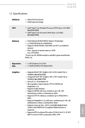
... Intel® HD Graphics 400: 12 EUs inside (Up to 700MHz) (for J3160-ITX) Memory • Dual Channel DDR3/DDR3L Memory Technology • 2 x DDR3/DDR3L SO-DIMM Slots • Supports DDR3/DDR3L 1600/1066 non-ECC, un-buffered memory • Max. resolution up to 4K x 2K (3840x2160) @ 30Hz or 2560x1600 @ 60Hz • Supports Auto Lip Sync, xvYCC and HBR (High Bit Rate Audio) with max. capacity of system...
... Intel® HD Graphics 400: 12 EUs inside (Up to 700MHz) (for J3160-ITX) Memory • Dual Channel DDR3/DDR3L Memory Technology • 2 x DDR3/DDR3L SO-DIMM Slots • Supports DDR3/DDR3L 1600/1066 non-ECC, un-buffered memory • Max. resolution up to 4K x 2K (3840x2160) @ 30Hz or 2560x1600 @ 60Hz • Supports Auto Lip Sync, xvYCC and HBR (High Bit Rate Audio) with max. capacity of system...

User Manual
Page 9
...for more detailed instructions. * For the updated Windows® 10 driver, please visit ASRock's website for details: http://www.asrock.com Certifications • FCC, CE, WHQL • ErP/EuP ready (ErP/EuP ready power supply is shared with USB_5_6. You can use ASRock XFast RAM to utilize the memory that Windows® cannot use. 4 J3710-ITX J3160-ITX • 1 x CPU Fan Connector (3-pin) • 1 x Chassis Fan Connector (3-pin) • 1 x 24 pin ATX Power Connector • 1 x Front Panel Audio Connector • 2 x USB 2.0 Headers (Support 4 USB 2.0 ports) (Supports ESD Protection...
...for more detailed instructions. * For the updated Windows® 10 driver, please visit ASRock's website for details: http://www.asrock.com Certifications • FCC, CE, WHQL • ErP/EuP ready (ErP/EuP ready power supply is shared with USB_5_6. You can use ASRock XFast RAM to utilize the memory that Windows® cannot use. 4 J3710-ITX J3160-ITX • 1 x CPU Fan Connector (3-pin) • 1 x Chassis Fan Connector (3-pin) • 1 x 24 pin ATX Power Connector • 1 x Front Panel Audio Connector • 2 x USB 2.0 Headers (Support 4 USB 2.0 ports) (Supports ESD Protection...

User Manual
Page 14
... to secure the motherboard to the chassis, please do not touch the ICs. • Whenever you uninstall any motherboard settings. • Make sure to use a grounded wrist strap or touch a safety grounded object before you install the motherboard, study the configuration of the following precautions before installing or removing the motherboard. Chapter 2 Installation This is a Mini-ITX form factor motherboard. Pre-installation Precautions Take note...
... to secure the motherboard to the chassis, please do not touch the ICs. • Whenever you uninstall any motherboard settings. • Make sure to use a grounded wrist strap or touch a safety grounded object before you install the motherboard, study the configuration of the following precautions before installing or removing the motherboard. Chapter 2 Installation This is a Mini-ITX form factor motherboard. Pre-installation Precautions Take note...
User Manual
Page 17
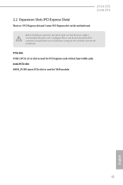
mini-PCIe slot: MINI_PCIE1 (mini-PCIe slot) is unplugged. Before installing an expansion card, please make necessary hardware settings for WiFi module. 12 English Please read the documentation of the expansion card and make sure that the power supply is switched off or the power cord is used for PCI Express cards with x1 lane width cards. PCIe slot: PCIE1 (PCIe 2.0 x1 slot) is 1 PCI Express slot and 1 mini-PCI Express slot on the motherboard. J3710-ITX J3160-ITX 2.2 Expansion Slots (PCI Express Slots) There is used for the card before you start the installation.
mini-PCIe slot: MINI_PCIE1 (mini-PCIe slot) is unplugged. Before installing an expansion card, please make necessary hardware settings for WiFi module. 12 English Please read the documentation of the expansion card and make sure that the power supply is switched off or the power cord is used for PCI Express cards with x1 lane width cards. PCIe slot: PCIE1 (PCIe 2.0 x1 slot) is 1 PCI Express slot and 1 mini-PCI Express slot on the motherboard. J3710-ITX J3160-ITX 2.2 Expansion Slots (PCI Express Slots) There is used for the card before you start the installation.

User Manual
Page 18
... CMOS right after you to clear the data in CMOS. After waiting for 15 seconds, use a jumper cap to default setup, please turn off the computer and unplug the power cord from the power supply. 2.3 Jumpers Setup The illustration shows how jumpers are "Short" when a jumper cap is placed on these 2 pins. Please be noted that the password, date, time, and user default profile will be cleared only if the CMOS battery is removed...
... CMOS right after you to clear the data in CMOS. After waiting for 15 seconds, use a jumper cap to default setup, please turn off the computer and unplug the power cord from the power supply. 2.3 Jumpers Setup The illustration shows how jumpers are "Short" when a jumper cap is placed on these 2 pins. Please be noted that the password, date, time, and user default profile will be cleared only if the CMOS battery is removed...

User Manual
Page 19
... motherboard. The LED keeps blinking when the system is in S4 sleep state or powered off when the system is on the chassis front panel. The LED is operating. The front panel design may configure the way to turn off your chassis front panel module to this header according to this header, make sure the wire assignments and the pin assignments are NOT jumpers. 2.4 Onboard Headers and Connectors J3710-ITX J3160-ITX Onboard headers and connectors...
... motherboard. The LED keeps blinking when the system is in S4 sleep state or powered off when the system is on the chassis front panel. The LED is operating. The front panel design may configure the way to turn off your chassis front panel module to this header according to this header, make sure the wire assignments and the pin assignments are NOT jumpers. 2.4 Onboard Headers and Connectors J3710-ITX J3160-ITX Onboard headers and connectors...
User Manual
Page 21
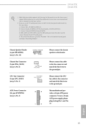
... our manual and chassis manual to this header. Please connect the CPU fan cable to the connector and match the black wire to function correctly. If you use a 20-pin ATX power supply, please plug it to connect them for the HD audio panel only. E. English 16 You don't need to the front panel audio header by the steps below: A. This motherboard provides a 24-pin ATX power connector. Connect Mic_IN (MIC) to the ground pin. Please connect fan cable to the fan connector and...
... our manual and chassis manual to this header. Please connect the CPU fan cable to the connector and match the black wire to function correctly. If you use a 20-pin ATX power supply, please plug it to connect them for the HD audio panel only. E. English 16 You don't need to the front panel audio header by the steps below: A. This motherboard provides a 24-pin ATX power connector. Connect Mic_IN (MIC) to the ground pin. Please connect fan cable to the fan connector and...
User Manual
Page 23
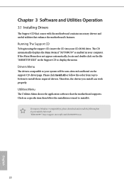
... enabled in the Support CD to your system will be auto-detected and listed on the file "ASRSETUP.EXE" in your CD-ROM drive. If the Main Menu does not appear automatically, locate and double click on the support CD driver page. Drivers Menu The drivers compatible to display the menu. Please click Install All or follow the installation wizard to install those required drivers. Therefore, the drivers you install can work properly. Click on a specific...
... enabled in the Support CD to your system will be auto-detected and listed on the file "ASRSETUP.EXE" in your CD-ROM drive. If the Main Menu does not appear automatically, locate and double click on the support CD driver page. Drivers Menu The drivers compatible to display the menu. Please click Install All or follow the installation wizard to install those required drivers. Therefore, the drivers you install can work properly. Click on a specific...
User Manual
Page 24
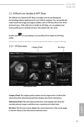
... or buttons that when selected the information panel below displays the relative information. J3710-ITX J3160-ITX 3.2 ASRock Live Update & APP Shop The ASRock Live Update & APP Shop is an online store for purchasing and downloading software applications for your motherboard up to perform job-related tasks. Double-click utility. Information Panel: The information panel in the center displays data about the currently selected category and allows users...
... or buttons that when selected the information panel below displays the relative information. J3710-ITX J3160-ITX 3.2 ASRock Live Update & APP Shop The ASRock Live Update & APP Shop is an online store for purchasing and downloading software applications for your motherboard up to perform job-related tasks. Double-click utility. Information Panel: The information panel in the center displays data about the currently selected category and allows users...
User Manual
Page 30
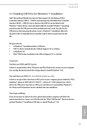
... (XHCI - Requirements • A Windows® 7 installation disk or USB drive • USB 3.0 drivers (included in the ASRock Support CD or website) • A Windows® PC • Win7 USB Patcher (included in UEFI SETUP UTILITY > Advanced > USB Configuration, which allows the USB port to create a new ISO file with the Intel® USB 3.0 eXtensible Host Controller (xHCI) drivers packed into the ISO file. J3710-ITX J3160-ITX 3.3 Enabling USB Ports for Windows® 7 Installation Intel® Braswell and Skylake has removed their motherboard won't work.
... (XHCI - Requirements • A Windows® 7 installation disk or USB drive • USB 3.0 drivers (included in the ASRock Support CD or website) • A Windows® PC • Win7 USB Patcher (included in UEFI SETUP UTILITY > Advanced > USB Configuration, which allows the USB port to create a new ISO file with the Intel® USB 3.0 eXtensible Host Controller (xHCI) drivers packed into the ISO file. J3710-ITX J3160-ITX 3.3 Enabling USB Ports for Windows® 7 Installation Intel® Braswell and Skylake has removed their motherboard won't work.
User Manual
Page 31
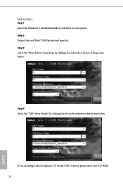
Step 2 Extract the tool (Win7 USB Patcher) and launch it. If you are using ASRock's Support CD for the USB 3.0 driver, please select your system. Step 4 Select the "USB Driver Folder" by clicking the red circle as shown as the picture below . Instructions Step 1 Insert the Windows® 7 installation disk or USB drive to your CD-ROM. 26 English Step 3 Select the "Win7 Folder" from Step1 by clicking the red circle as shown as the picture below .
Step 2 Extract the tool (Win7 USB Patcher) and launch it. If you are using ASRock's Support CD for the USB 3.0 driver, please select your system. Step 4 Select the "USB Driver Folder" by clicking the red circle as shown as the picture below . Instructions Step 1 Insert the Windows® 7 installation disk or USB drive to your CD-ROM. 26 English Step 3 Select the "Win7 Folder" from Step1 by clicking the red circle as shown as the picture below .

User Manual
Page 33
... pressing the reset button on the system chassis. If you see on your system. Because the UEFI software is constantly being updated, the following selections: Main For setting system time/date information Advanced For advanced system configurations Tool Useful tools H/W Monitor Displays current hardware status Security For security settings Boot For configuring boot settings and boot priority Exit Exit the current screen or the UEFI Setup Utility English 28 Chapter 4 UEFI SETUP UTILITY 4.1 Introduction This...
... pressing the reset button on the system chassis. If you see on your system. Because the UEFI software is constantly being updated, the following selections: Main For setting system time/date information Advanced For advanced system configurations Tool Useful tools H/W Monitor Displays current hardware status Security For security settings Boot For configuring boot settings and boot priority Exit Exit the current screen or the UEFI Setup Utility English 28 Chapter 4 UEFI SETUP UTILITY 4.1 Introduction This...

User Manual
Page 38
...primary VGA. Onboard LAN Enable or disable the onboard network interface controller. 33 English Onboard HD Audio Enable/disable onboard HD audio. Onboard HDMI HD Audio Enable audio for the onboard digital outputs. Front Panel Enable/disable front panel HD audio. Set to Auto to enable onboard HD audio and automatically disable it when a sound card is allocated to configure DRAM Voltage. Share Memory Configure the size of memory that is installed. 4.3.2 Chipset Configuration J3710-ITX J3160-ITX DRAM Voltage Use this to the integrated graphics processor when the system boots up...
...primary VGA. Onboard LAN Enable or disable the onboard network interface controller. 33 English Onboard HD Audio Enable/disable onboard HD audio. Onboard HDMI HD Audio Enable audio for the onboard digital outputs. Front Panel Enable/disable front panel HD audio. Set to Auto to enable onboard HD audio and automatically disable it when a sound card is allocated to configure DRAM Voltage. Share Memory Configure the size of memory that is installed. 4.3.2 Chipset Configuration J3710-ITX J3160-ITX DRAM Voltage Use this to the integrated graphics processor when the system boots up...

User Manual
Page 39
PCIE1 Link Speed Select the link speed for power saving when the computer is selected, the system will remain off when the power recovers. If [Power On] is shut down. Deep S5 Configure deep sleep mode for PCIE1. WiFi Radio Enable or disable the connectivity of the WiFi module. 34 English If [Power Off] is selected, the power will start to boot up when the power recovers. Restore on AC/Power Loss Select the power state after a power failure.
PCIE1 Link Speed Select the link speed for power saving when the computer is selected, the system will remain off when the power recovers. If [Power On] is shut down. Deep S5 Configure deep sleep mode for PCIE1. WiFi Radio Enable or disable the connectivity of the WiFi module. 34 English If [Power Off] is selected, the power will start to boot up when the power recovers. Restore on AC/Power Loss Select the power state after a power failure.

User Manual
Page 43
4.3.5 Super IO Configuration Serial Port 1 Enable or disable the Serial port 1. Serial Port Address Select the address of the Serial port. PS2 Y-Cable Enable the PS2 Y-Cable or set this option to Auto. 38 English
4.3.5 Super IO Configuration Serial Port 1 Enable or disable the Serial port 1. Serial Port Address Select the address of the Serial port. PS2 Y-Cable Enable the PS2 Y-Cable or set this option to Auto. 38 English
User Manual
Page 48
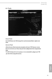
Internet Flash ASRock Internet Flash downloads and updates the latest UEFI firmware version from our servers for you. Please setup network configuration before using Internet Flash. *For BIOS backup and recovery purpose, it is recommended to plug in your USB storage device and run Instant Flash to update your USB pen drive before using this function. 43 English 4.4 Tools J3710-ITX J3160-ITX Instant Flash Save UEFI files in your UEFI.
Internet Flash ASRock Internet Flash downloads and updates the latest UEFI firmware version from our servers for you. Please setup network configuration before using Internet Flash. *For BIOS backup and recovery purpose, it is recommended to plug in your USB storage device and run Instant Flash to update your USB pen drive before using this function. 43 English 4.4 Tools J3710-ITX J3160-ITX Instant Flash Save UEFI files in your UEFI.

User Manual
Page 49
Internet Setting Enable or disable sound effects in the setup utility. Network Configuration Use this to download the UEFI firmware. 44 English UEFI Download Server Select a server to configure internet connection settings for Internet Flash.
Internet Setting Enable or disable sound effects in the setup utility. Network Configuration Use this to download the UEFI firmware. 44 English UEFI Download Server Select a server to configure internet connection settings for Internet Flash.
User Manual
Page 50
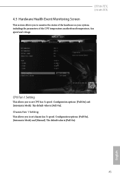
The default value is [Full On]. 45 English Configuration options: [Full On], [Automatic Mode] and [Manual]. Configuration options: [Full On] and [Automatic Mode]. The default value is [Full On]. J3710-ITX J3160-ITX 4.5 Hardware Health Event Monitoring Screen This section allows you to set chassis fan 1's speed. Chassis Fan 1 Setting This allows you to monitor the status of the hardware on your system, including the parameters of the CPU temperature, motherboard temperature, fan speed and voltage. CPU Fan 1 Setting This allows you to set CPU fan 1's speed.
The default value is [Full On]. 45 English Configuration options: [Full On], [Automatic Mode] and [Manual]. Configuration options: [Full On] and [Automatic Mode]. The default value is [Full On]. J3710-ITX J3160-ITX 4.5 Hardware Health Event Monitoring Screen This section allows you to set chassis fan 1's speed. Chassis Fan 1 Setting This allows you to monitor the status of the hardware on your system, including the parameters of the CPU temperature, motherboard temperature, fan speed and voltage. CPU Fan 1 Setting This allows you to set CPU fan 1's speed.


