
User Manual
Page 9
... to access ASRock Instant Flash. The voltage regulator can press key during the POST or press key to BIOS setup menu to perform over-clocking. ASRock website: http://www.asrock.com 12. While CPU overheat is a BIOS flash utility embedded in the BIOS setup, the memory performance will improve up to 12.5%, but the effect still depends on the motherboard functions properly and unplug the power cord, then plug it is a user-friendly ASRock overclocking tool...
... to access ASRock Instant Flash. The voltage regulator can press key during the POST or press key to BIOS setup menu to perform over-clocking. ASRock website: http://www.asrock.com 12. While CPU overheat is a BIOS flash utility embedded in the BIOS setup, the memory performance will improve up to 12.5%, but the effect still depends on the motherboard functions properly and unplug the power cord, then plug it is a user-friendly ASRock overclocking tool...

User Manual
Page 12
... Module Header (IR1) 6 CPU Fan Connector (CPU_FAN1) 21 Print Port Header (LPT1, Purple) 7 ATX Power Connector (ATXPWR1) 22 Floppy Connector (FLOPPY1) 8 Primary IDE Connector (IDE1, Blue) 23 Serial Port Connector (COM1) 9 SATAII Connector (SATAII_2 (PORT 1), Red) 24 Internal Audio Connector: CD1 (Black) 10 SATAII Connector (SATAII_4 (PORT 3), Red) 25 Front Panel Audio Header 11 SATAII Connector (SATAII_1 (PORT 0), Red) (HD_AUDIO1, Lime) 12 SATAII Connector (SATAII_3 (PORT 2), Red) 26 PCI Slots (PCI1- 2) 13 SPI BIOS Chip 27 PCI Express x16 Slot (PCIE2, Green) 14 Clear CMOS Jumper...
... Module Header (IR1) 6 CPU Fan Connector (CPU_FAN1) 21 Print Port Header (LPT1, Purple) 7 ATX Power Connector (ATXPWR1) 22 Floppy Connector (FLOPPY1) 8 Primary IDE Connector (IDE1, Blue) 23 Serial Port Connector (COM1) 9 SATAII Connector (SATAII_2 (PORT 1), Red) 24 Internal Audio Connector: CD1 (Black) 10 SATAII Connector (SATAII_4 (PORT 3), Red) 25 Front Panel Audio Header 11 SATAII Connector (SATAII_1 (PORT 0), Red) (HD_AUDIO1, Lime) 12 SATAII Connector (SATAII_3 (PORT 2), Red) 26 PCI Slots (PCI1- 2) 13 SPI BIOS Chip 27 PCI Express x16 Slot (PCIE2, Green) 14 Clear CMOS Jumper...
User Manual
Page 20
... visit our website for future update. B. Power off your system. Connect the monitor cable to PCIE2 slot (green). The default setting is in the following path of ASRock support CD: (There are two ASRock support CD in the motherboard gift box pack, please choose the one compatible PCI Express graphics card to the correspondent connector on your computer. Install one for Windows® VistaTM / VistaTM 64-bit.) ..\Drivers\Hybrid SLI driver\Vista * Currently, Hybrid SLITM...
... visit our website for future update. B. Power off your system. Connect the monitor cable to PCIE2 slot (green). The default setting is in the following path of ASRock support CD: (There are two ASRock support CD in the motherboard gift box pack, please choose the one compatible PCI Express graphics card to the correspondent connector on your computer. Install one for Windows® VistaTM / VistaTM 64-bit.) ..\Drivers\Hybrid SLI driver\Vista * Currently, Hybrid SLITM...

User Manual
Page 21
... monitor cable to enter BIOS setup. Install Hybrid SLITM driver from our support CD to your Win- Then you will find the Hybrid icon on your system. dows® taskbar. Install one monitor cable to PCIE2 slot (green). Step 2. Step 3. Restart your system. Click the desktop. C. Dual Monitors Step 1. Connect one compatible PCI Express graphics card to the correspondent connector on PCIE2 slot. Step 5. Step 6. Press to the correspondent connector on the PCI Express graphics card on the I/O shield. Boot...
... monitor cable to enter BIOS setup. Install Hybrid SLITM driver from our support CD to your Win- Then you will find the Hybrid icon on your system. dows® taskbar. Install one monitor cable to PCIE2 slot (green). Step 2. Step 3. Restart your system. Click the desktop. C. Dual Monitors Step 1. Connect one compatible PCI Express graphics card to the correspondent connector on PCIE2 slot. Step 5. Step 6. Press to the correspondent connector on the PCI Express graphics card on the I/O shield. Boot...
User Manual
Page 25
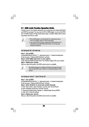
... your system. For Windows® XP / XP 64-bit OS Step 1: Set up BIOS. B. Step 2: Install HDMI audio driver to "Digital Output Device (HDMI)". Step 3: Reboot your system. Therefore, the onboard audio jack will output the audio signal through HDMI audio. Enter BIOS SETUP UTILITY Advanced screen Chipset Configuration. Set the option "OnBoard HDMI HD Audio" to set up your system manually. Step 2: Enter Windows® to [Auto]. Click "Start" button, select "Settings", and then click "Control Panel". B. C. Change the default setting "Speaker" to your system...
... your system. For Windows® XP / XP 64-bit OS Step 1: Set up BIOS. B. Step 2: Install HDMI audio driver to "Digital Output Device (HDMI)". Step 3: Reboot your system. Therefore, the onboard audio jack will output the audio signal through HDMI audio. Enter BIOS SETUP UTILITY Advanced screen Chipset Configuration. Set the option "OnBoard HDMI HD Audio" to set up your system manually. Step 2: Enter Windows® to [Auto]. Click "Start" button, select "Settings", and then click "Control Panel". B. C. Change the default setting "Speaker" to your system...

User Manual
Page 35
... boot devices selection appears. Then, the drivers compatible to your system. (There are two ASRock Support CD in the motherboard gift box pack, please choose the one for WindowsXP64 4. Enter BIOS SETUP UTILITY Advanced screen IDE Configuration. C. Generate RAID Driver diskette for WindowsXP 2. Exit Reboot system now Press any key to install those required drivers. 2.14 Driver Installation Guide To install the drivers to your system, please insert the support CD to your SATA / SATAII HDDs without RAID...
... boot devices selection appears. Then, the drivers compatible to your system. (There are two ASRock Support CD in the motherboard gift box pack, please choose the one for WindowsXP64 4. Enter BIOS SETUP UTILITY Advanced screen IDE Configuration. C. Generate RAID Driver diskette for WindowsXP 2. Exit Reboot system now Press any key to install those required drivers. 2.14 Driver Installation Guide To install the drivers to your system, please insert the support CD to your SATA / SATAII HDDs without RAID...

User Manual
Page 38
... the following path in RAID mode. (There are in the following path in BIOS first. Please refer to set the RAID configuration by using the Windows RAID installation guide part of the document in the following path in our Support CD: (There are as below steps. After reading the floppy disk, the drivers will be presented. Set the "SATA Operation Mode" option to check the RAID installation guide in the motherboard gift box pack...
... the following path in RAID mode. (There are in the following path in BIOS first. Please refer to set the RAID configuration by using the Windows RAID installation guide part of the document in the following path in our Support CD: (There are as below steps. After reading the floppy disk, the drivers will be presented. Set the "SATA Operation Mode" option to check the RAID installation guide in the motherboard gift box pack...
User Manual
Page 46
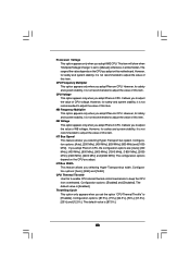
... this motherboard. The default value is [Enabled]. The range of the value depends on this item. NB Frequency Multiplier This option appears only when you adopt Phenom CPU. Configuration options: [Auto], [200 MHz], [400 MHz], [600 MHz], [800 MHz] and [1000 MHz]. Configuration options: [Auto], [8 Bit] and [16 Bit]. The default value is [87.5%]. 46 CPU Frequency Multiplier This option appears only when you adopt Phenom CPU. Processor Voltage This option appears...
... this motherboard. The default value is [Enabled]. The range of the value depends on this item. NB Frequency Multiplier This option appears only when you adopt Phenom CPU. Configuration options: [Auto], [200 MHz], [400 MHz], [600 MHz], [800 MHz] and [1000 MHz]. Configuration options: [Auto], [8 Bit] and [16 Bit]. The default value is [87.5%]. 46 CPU Frequency Multiplier This option appears only when you adopt Phenom CPU. Processor Voltage This option appears...
User Manual
Page 54
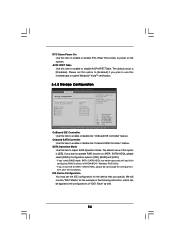
... SATA Operation Mode. We will use this motherboard to enable or disable ACPI HPET Table. The default value is [IDE]. Onboard SATA Controller Use this item to the configurations of this item after OS installation. Configuration options: [IDE], [RAID] and [AHCI]. * If you install OS on the system. IDE Device Configuration You may set this option to [Enabled] if you specify. ACPI HPET Table Use this item to submit Windows® VistaTM certification. 3.4.5 Storage Configuration BIOS SETUP UTILITY Advanced Storage Configuration OnBoard IDE Controller Onboard SATA Controller SATA...
... SATA Operation Mode. We will use this motherboard to enable or disable ACPI HPET Table. The default value is [IDE]. Onboard SATA Controller Use this item to the configurations of this item after OS installation. Configuration options: [IDE], [RAID] and [AHCI]. * If you install OS on the system. IDE Device Configuration You may set this option to [Enabled] if you specify. ACPI HPET Table Use this item to submit Windows® VistaTM certification. 3.4.5 Storage Configuration BIOS SETUP UTILITY Advanced Storage Configuration OnBoard IDE Controller Onboard SATA Controller SATA...
User Manual
Page 58
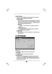
...[IRQ7]. 3.4.9 USB Configuration BIOS SETUP UTILITY Advanced USB Configuration USB Controller USB 2.0 Support Legacy USB Support [Enabled] [Enabled] [Enabled] To enable or disable the onboard USB controllers. +F1 F9 F10 ESC Select Screen Select Item Change Option General Help Load Defaults Save and Exit Exit v02.54 (C) Copyright 1985-2003, American Megatrends, Inc. EPP Version Use this item to set the ECP mode DMA channel. Please refer to below descriptions for USB devices. The default value is [ECP+EPP]. Legacy USB Support Use this option to select legacy support for the...
...[IRQ7]. 3.4.9 USB Configuration BIOS SETUP UTILITY Advanced USB Configuration USB Controller USB 2.0 Support Legacy USB Support [Enabled] [Enabled] [Enabled] To enable or disable the onboard USB controllers. +F1 F9 F10 ESC Select Screen Select Item Change Option General Help Load Defaults Save and Exit Exit v02.54 (C) Copyright 1985-2003, American Megatrends, Inc. EPP Version Use this item to set the ECP mode DMA channel. Please refer to below descriptions for USB devices. The default value is [ECP+EPP]. Legacy USB Support Use this option to select legacy support for the...
User Manual
Page 61
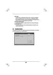
... Enter Change F1 General Help F9 Load Defaults F10 Save and Exit ESC Exit v02.54 (C) Copyright 1985-2005, American Megatrends, Inc. 61 Configuration options: [Auto], [PCIE2.0 Revolution], [Scenery] and [ASRock]. Boot Up Num-Lock If this item is [Auto]. BIOS SETUP UTILITY Main Smart Advanced H/W Monitor Boot Security Exit Security Settings Supervisor Password : Not Installed User Password : Not Installed Change Supervisor Password Change User Password Install or Change the password. The default value is set to [On], it . Boot Logo Use this option to enable or disable...
... Enter Change F1 General Help F9 Load Defaults F10 Save and Exit ESC Exit v02.54 (C) Copyright 1985-2005, American Megatrends, Inc. 61 Configuration options: [Auto], [PCIE2.0 Revolution], [Scenery] and [ASRock]. Boot Up Num-Lock If this item is [Auto]. BIOS SETUP UTILITY Main Smart Advanced H/W Monitor Boot Security Exit Security Settings Supervisor Password : Not Installed User Password : Not Installed Change Supervisor Password Change User Password Install or Change the password. The default value is set to [On], it . Boot Logo Use this option to enable or disable...

User Manual
Page 63
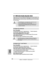
... ASRock, welcome to display the menus. 4.2.2 Drivers Menu The Drivers Menu shows the available devices drivers if the system detects the installed devices. Because motherboard settings and hardware options vary, use the setup procedures in the Support CD to visit ASRock's website at http://www.asrock.com; Software Support 4.1 Install Operating System This motherboard supports various Microsoft® Windows® operating systems: XP / XP Media Center / XP 64-bit / VistaTM / VistaTM 64-bit. Click on the file...
... ASRock, welcome to display the menus. 4.2.2 Drivers Menu The Drivers Menu shows the available devices drivers if the system detects the installed devices. Because motherboard settings and hardware options vary, use the setup procedures in the Support CD to visit ASRock's website at http://www.asrock.com; Software Support 4.1 Install Operating System This motherboard supports various Microsoft® Windows® operating systems: XP / XP Media Center / XP 64-bit / VistaTM / VistaTM 64-bit. Click on the file...
Quick Installation Guide
Page 2
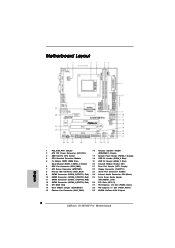
... Audio Header 11 SATAII Connector (SATAII_1 (PORT 0), Red) (HD_AUDIO1, Lime) 12 SATAII Connector (SATAII_3 (PORT 2), Red) 26 PCI Slots (PCI1- 2) 13 SPI BIOS Chip 27 PCI Express x16 Slot (PCIE2, Green) 14 Clear CMOS Jumper (CLRCMOS1) 28 PCI Express x1 Slot (PCIE1, White) 15 Chassis Fan Connector (CHA_FAN1) 29 NVIDIA GeForce 8100 Chipset 2 ASRock K10N78M Pro Motherboard Motherboard Layout English 1 PS2_USB_PW1 Jumper 16 Chassis Speaker Header 2 ATX 12V Power Connector (ATX12V1) (SPEAKER 1, Purple) 3 AM2 940-Pin CPU Socket 17 System Panel Header (PANEL1, Orange) 4 CPU Heatsink...
... Audio Header 11 SATAII Connector (SATAII_1 (PORT 0), Red) (HD_AUDIO1, Lime) 12 SATAII Connector (SATAII_3 (PORT 2), Red) 26 PCI Slots (PCI1- 2) 13 SPI BIOS Chip 27 PCI Express x16 Slot (PCIE2, Green) 14 Clear CMOS Jumper (CLRCMOS1) 28 PCI Express x1 Slot (PCIE1, White) 15 Chassis Fan Connector (CHA_FAN1) 29 NVIDIA GeForce 8100 Chipset 2 ASRock K10N78M Pro Motherboard Motherboard Layout English 1 PS2_USB_PW1 Jumper 16 Chassis Speaker Header 2 ATX 12V Power Connector (ATX12V1) (SPEAKER 1, Purple) 3 AM2 940-Pin CPU Socket 17 System Panel Header (PANEL1, Orange) 4 CPU Heatsink...

Quick Installation Guide
Page 6
... AHCI and "Hot Plug" functions (see CAUTION 8) - 1 x ATA133 IDE connector (supports 2 x IDE devices) - 1 x Floppy connector - 1 x IR header - 1 x Print port header - 1 x COM port header - Hybrid Booster: - ASRock U-COP (see CAUTION 9) BIOS Feature - 8Mb AMI BIOS - CPU Quiet Fan 6 ASRock K10N78M Pro Motherboard Front panel audio connector - 2 x USB 2.0 headers (support 4 USB 2.0 ports) (see CAUTION 14) English - Drivers, Utilities, AntiVirus Software (Trial Version) Unique Feature - ASRock Instant Flash (see CAUTION 10) - Boot Failure Guard (B.F.G.) - Chassis...
... AHCI and "Hot Plug" functions (see CAUTION 8) - 1 x ATA133 IDE connector (supports 2 x IDE devices) - 1 x Floppy connector - 1 x IR header - 1 x Print port header - 1 x COM port header - Hybrid Booster: - ASRock U-COP (see CAUTION 9) BIOS Feature - 8Mb AMI BIOS - CPU Quiet Fan 6 ASRock K10N78M Pro Motherboard Front panel audio connector - 2 x USB 2.0 headers (support 4 USB 2.0 ports) (see CAUTION 14) English - Drivers, Utilities, AntiVirus Software (Trial Version) Unique Feature - ASRock Instant Flash (see CAUTION 10) - Boot Failure Guard (B.F.G.) - Chassis...
Quick Installation Guide
Page 8
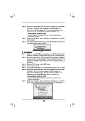
... key to BIOS setup menu to update system BIOS without sacrificing computing performance. If you enable this tool and save the new BIOS file to your USB flash drive, floppy disk or hard drive, then you resume the system, please check if the CPU fan on the AM2 CPU you to access ASRock Instant Flash. However, we can reduce the number of your system. This motherboard supports ASRock AM2 Boost overclocking technology for all CPU/DRAM configurations. Enabling this motherboard offers stepless control...
... key to BIOS setup menu to update system BIOS without sacrificing computing performance. If you enable this tool and save the new BIOS file to your USB flash drive, floppy disk or hard drive, then you resume the system, please check if the CPU fan on the AM2 CPU you to access ASRock Instant Flash. However, we can reduce the number of your system. This motherboard supports ASRock AM2 Boost overclocking technology for all CPU/DRAM configurations. Enabling this motherboard offers stepless control...

Quick Installation Guide
Page 17
... system. And set the option "Hybrid SLI" to your system. Save your Windows® taskbar. Step 7. English 17 ASRock K10N78M Pro Motherboard Step 4. The default setting is in the following path of ASRock support CD: (There are two ASRock support CD in the motherboard gift box pack, please choose the one compatible PCI Express graphics card to [Onboard]. Then set the option "Primary Graphics Display" to PCIE2 slot (green). Step 6. Boot into OS. Hybrid SLITM driver is in...
... system. And set the option "Hybrid SLI" to your system. Save your Windows® taskbar. Step 7. English 17 ASRock K10N78M Pro Motherboard Step 4. The default setting is in the following path of ASRock support CD: (There are two ASRock support CD in the motherboard gift box pack, please choose the one compatible PCI Express graphics card to [Onboard]. Then set the option "Primary Graphics Display" to PCIE2 slot (green). Step 6. Boot into OS. Hybrid SLITM driver is in...
Quick Installation Guide
Page 18
... system. Click the desktop. Boot your computer. Install Hybrid SLITM driver from our support CD to enter BIOS setup. Then set the option "Share Memory" to Dual Monitors mode (Additional Displays). 18 ASRock K10N78M Pro Motherboard English Boot into OS. Then your Windows® taskbar. Step 2. For the proper installation procedures, please refer to the correspondent connector on the I/O shield. Enter "Advanced" screen, and enter "Chipset Settings". Connect the other monitor cable to the correspondent connector on the PCI Express graphics card on your system is...
... system. Click the desktop. Boot your computer. Install Hybrid SLITM driver from our support CD to enter BIOS setup. Then set the option "Share Memory" to Dual Monitors mode (Additional Displays). 18 ASRock K10N78M Pro Motherboard English Boot into OS. Then your Windows® taskbar. Step 2. For the proper installation procedures, please refer to the correspondent connector on the I/O shield. Enter "Advanced" screen, and enter "Chipset Settings". Connect the other monitor cable to the correspondent connector on the PCI Express graphics card on your system is...
Quick Installation Guide
Page 22
... audio driver is available. For Windows® VistaTM / VistaTM 64-bit OS Step 1: Set up BIOS. A. Enter BIOS SETUP UTILITY Advanced screen Chipset Configuration. Set the option "OnBoard HDMI HD Audio" to [Auto]. Click "Start" button, select "Settings", and then click "Control Panel". B. C. You may pause sometimes. DVI to HDMI adapter is available. Set the option "OnBoard HDMI HD Audio" to [Auto]. D. After you install the DVI-D monitor instead of the HDMI monitor on this motherboard can support DVI/HDCP and HDMI format signal. Click "Hardware and Sound...
... audio driver is available. For Windows® VistaTM / VistaTM 64-bit OS Step 1: Set up BIOS. A. Enter BIOS SETUP UTILITY Advanced screen Chipset Configuration. Set the option "OnBoard HDMI HD Audio" to [Auto]. Click "Start" button, select "Settings", and then click "Control Panel". B. C. You may pause sometimes. DVI to HDMI adapter is available. Set the option "OnBoard HDMI HD Audio" to [Auto]. D. After you install the DVI-D monitor instead of the HDMI monitor on this motherboard can support DVI/HDCP and HDMI format signal. Click "Hardware and Sound...
RAID Installation Guide
Page 6
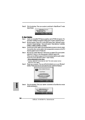
... using the Windows RAID installation guide part of Windows® setup, press F6 to the BIOS RAID installation guide part of the document in the following path in RAID mode. (There are as below: A. Then, please set RAID configuration. After reading the floppy disk, the drivers will be presented. Please refer to install a third-party RAID driver. NVIDIA nForce Storage Controller (required) Please select A and B for RAID mode, you need to set up "SATA Operation Mode" to check the RAID installation guide in the Support...
... using the Windows RAID installation guide part of Windows® setup, press F6 to the BIOS RAID installation guide part of the document in the following path in RAID mode. (There are as below: A. Then, please set RAID configuration. After reading the floppy disk, the drivers will be presented. Please refer to install a third-party RAID driver. NVIDIA nForce Storage Controller (required) Please select A and B for RAID mode, you need to set up "SATA Operation Mode" to check the RAID installation guide in the Support...

RAID Installation Guide
Page 7
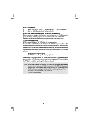
... set up "SATA Operation Mode" to [RAID] in the Support CD: .. \ RAID Installation Guide STEP 3: Install Windows® VistaTM / VistaTM 64-bit OS on your optical drive, and click the "Load Driver" button on the left on the bottom to load the NVIDIA® RAID drivers. Enter BIOS SETUP UTILITY Advanced screen IDE Configuration. Set the "SATA Operation Mode" option to install Windows?" Insert the Windows® VistaTM / Windows® VistaTM 64-bit optical disk into the optical drive to boot your system, and follow the instruction to install Windows...
... set up "SATA Operation Mode" to [RAID] in the Support CD: .. \ RAID Installation Guide STEP 3: Install Windows® VistaTM / VistaTM 64-bit OS on your optical drive, and click the "Load Driver" button on the left on the bottom to load the NVIDIA® RAID drivers. Enter BIOS SETUP UTILITY Advanced screen IDE Configuration. Set the "SATA Operation Mode" option to install Windows?" Insert the Windows® VistaTM / Windows® VistaTM 64-bit optical disk into the optical drive to boot your system, and follow the instruction to install Windows...


