Aspire 1350 Service Guide
Page 7
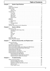
...33 Boot 37 Exit 38 BIOS Flash Utility 39 System Diagnostic Diskette 39 Chapter 3 Machine Disassembly and Replacement 41 General Information 42 Before You Begin 42 Disassembly Procedure Flowchart 43 Removing the Battery Pack 45 Removing the Memory/MDC (Modem/Bluetooth)/HDD... Keyboard/ODD Module/FDD Module 47 Disassembling the Main Unit 49 Disassembling the LCD Module 54 Disassembling the LCD Module-15.1 Inch 42 Disassembling the External Modules 57 Disassembling the HDD Module 57 Disassembling the Floppy Disk Drive Module 57 Disassembling the Optical Drive Module 58 Chapter ...
...33 Boot 37 Exit 38 BIOS Flash Utility 39 System Diagnostic Diskette 39 Chapter 3 Machine Disassembly and Replacement 41 General Information 42 Before You Begin 42 Disassembly Procedure Flowchart 43 Removing the Battery Pack 45 Removing the Memory/MDC (Modem/Bluetooth)/HDD... Keyboard/ODD Module/FDD Module 47 Disassembling the Main Unit 49 Disassembling the LCD Module 54 Disassembling the LCD Module-15.1 Inch 42 Disassembling the External Modules 57 Disassembling the HDD Module 57 Disassembling the Floppy Disk Drive Module 57 Disassembling the Optical Drive Module 58 Chapter ...
Aspire 1350 Service Guide
Page 49
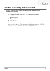
... Replacement This chapter contains step-by-step procedures on how to disassemble the notebook computer for the different components vary in size. During the disassembly process, group the screws with the corresponding components to scrape the cover. To disassemble the computer, you remove the stripe cover, please be careful not to avoid mismatch...
... Replacement This chapter contains step-by-step procedures on how to disassemble the notebook computer for the different components vary in size. During the disassembly process, group the screws with the corresponding components to scrape the cover. To disassemble the computer, you remove the stripe cover, please be careful not to avoid mismatch...
Aspire 1350 Service Guide
Page 50
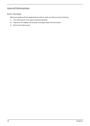
General Information Before You Begin Before proceeding with the disassembly procedure, make sure that you do the following: 1. Turn off the power to the system and all power and signal cables from the system. 3. Unplug the AC adapter and all peripherals. 2. Remove the battery pack. 42 Chapter 3
General Information Before You Begin Before proceeding with the disassembly procedure, make sure that you do the following: 1. Turn off the power to the system and all power and signal cables from the system. 3. Unplug the AC adapter and all peripherals. 2. Remove the battery pack. 42 Chapter 3
Aspire 1350 Service Guide
Page 51
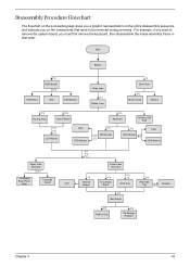
For example, if you want to remove the system board, you on the entire disassembly sequence and instructs you must first remove the keyboard, then disassemble the inside assembly frame in that need to be removed during servicing. Disassembly Procedure Flowchart The flowchart on the succeeding page gives you a graphic representation on the components...
For example, if you want to remove the system board, you on the entire disassembly sequence and instructs you must first remove the keyboard, then disassemble the inside assembly frame in that need to be removed during servicing. Disassembly Procedure Flowchart The flowchart on the succeeding page gives you a graphic representation on the components...
Aspire 1350 Service Guide
Page 57
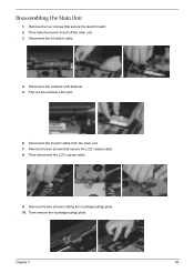
Chapter 3 49 Remove the four screws that secure the LCD coaxial cable. 8. Pop out the wireless LAN card. 6. Remove the two screws that secure the launch board. 2. Disconnect the wireless LAN antenna. 5. Remove the two screws holding the rounting(routing) plate. 10. Then take the launch board off the main unit. 3. Disconnect the inverter cable from the main unit. 7. Disconnect the lid switch cable. . 4. Then disconnect the LCD coaxial cable. 9. Disassembling the Main Unit 1. Then remove the rounting(routing) plate. .
Chapter 3 49 Remove the four screws that secure the LCD coaxial cable. 8. Pop out the wireless LAN card. 6. Remove the two screws that secure the launch board. 2. Disconnect the wireless LAN antenna. 5. Remove the two screws holding the rounting(routing) plate. 10. Then take the launch board off the main unit. 3. Disconnect the inverter cable from the main unit. 7. Disconnect the lid switch cable. . 4. Then disconnect the LCD coaxial cable. 9. Disassembling the Main Unit 1. Then remove the rounting(routing) plate. .
Aspire 1350 Service Guide
Page 62
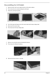
Detach the LCD bezel carefully. . 4. Then remove the four screws holding the LCD bezel. 3. Remove the three screws on one screw that fastens the LCD inverter cable and the high voltage cable. 5. Disconnect the inverter cable. 6. Remove one side. 54 Chapter 3 Tear off the tape that secures the Bluetooth antenna. 8. Remove the two LCD cover rubbers and two LCD cushion rubbers. 2. Then disconnect the high voltage cable. 7. Then remove the Bluetooth antenna. 9. Disassembling the LCD Module 1.
Detach the LCD bezel carefully. . 4. Then remove the four screws holding the LCD bezel. 3. Remove the three screws on one screw that fastens the LCD inverter cable and the high voltage cable. 5. Disconnect the inverter cable. 6. Remove one side. 54 Chapter 3 Tear off the tape that secures the Bluetooth antenna. 8. Remove the two LCD cover rubbers and two LCD cushion rubbers. 2. Then disconnect the high voltage cable. 7. Then remove the Bluetooth antenna. 9. Disassembling the LCD Module 1.
Aspire 1350 Service Guide
Page 65
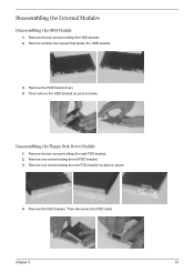
Then remove the HDD bracket as picture shows. 4. Remove the two screws holding the HDD bracket. 2. Remove the FDD bracket. Remove one screw hloding the rear FDD bracket as picture shows. Chapter 3 57 Disassembling the External Modules Disassembling the HDD Module 1. Then disconnect the FDD cable. Remove the HDD bezel(cover). 4. Remove one screw hloding the left FDD bracket. 3. Disassembling the Floppy Disk Drive Module 1. Remove the two screws holding the right FDD bracket. 2. Remove another two screws that fasten the HDD bracket. 3.
Then remove the HDD bracket as picture shows. 4. Remove the two screws holding the HDD bracket. 2. Remove the FDD bracket. Remove one screw hloding the rear FDD bracket as picture shows. Chapter 3 57 Disassembling the External Modules Disassembling the HDD Module 1. Then disconnect the FDD cable. Remove the HDD bezel(cover). 4. Remove one screw hloding the left FDD bracket. 3. Disassembling the Floppy Disk Drive Module 1. Remove the two screws holding the right FDD bracket. 2. Remove another two screws that fasten the HDD bracket. 3.
Aspire 1350 Service Guide
Page 66
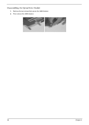
Remove the two screws that secure the ODD bracket. 2. Then remove the ODD bracket. 58 Chapter 3 Disassembling the Optical Drive Module 1.
Remove the two screws that secure the ODD bracket. 2. Then remove the ODD bracket. 58 Chapter 3 Disassembling the Optical Drive Module 1.
Aspire 1350 Service Guide
Page 67
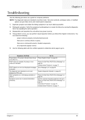
... by running the diagnostic test or by repeating the same operation. 3. Use the following : power cords are indicated. Distinguish symptom. Disassemble and assemble the unit without any problem occurs, you fellow this model. If any power sources. 4. Chapter 4 Troubleshooting Use the ...following procedure as possible. 2. Non-Acer products, prototype cards, or modified options can perform visual inspection before you can give false errors and invalid system responses. 1. POST...
... by running the diagnostic test or by repeating the same operation. 3. Use the following : power cords are indicated. Distinguish symptom. Disassemble and assemble the unit without any problem occurs, you fellow this model. If any power sources. 4. Chapter 4 Troubleshooting Use the ...following procedure as possible. 2. Non-Acer products, prototype cards, or modified options can perform visual inspection before you can give false errors and invalid system responses. 1. POST...
Aspire 1350 User Guide
Page 86
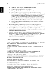
... I STRÅLEN. e If the product has been dropped or the case has been damaged. b If liquid has been spilled into the product. Do not disassemble or dispose of other controls may explode if not handled properly. LAVATTAESSA OLET ALTTINA LASERSÅTEILYLLE. VARNING: LASERSTRÅLNING NÅR DENNA DEL Å...
... I STRÅLEN. e If the product has been dropped or the case has been damaged. b If liquid has been spilled into the product. Do not disassemble or dispose of other controls may explode if not handled properly. LAVATTAESSA OLET ALTTINA LASERSÅTEILYLLE. VARNING: LASERSTRÅLNING NÅR DENNA DEL Å...

Aspire 1350 User Guide
Page 88
.... patents and other intellectual property rights owned by Macrovision Corporation and other limited viewing uses only unless otherwise authorized by Macrovision Corporation. Reverse engineering or disassembly is intended for limited viewing uses only. Apparatus Claims of certain U.S. Use of this copyright protection technology must be authorized by method claims of U.S. 78...
.... patents and other intellectual property rights owned by Macrovision Corporation and other limited viewing uses only unless otherwise authorized by Macrovision Corporation. Reverse engineering or disassembly is intended for limited viewing uses only. Apparatus Claims of certain U.S. Use of this copyright protection technology must be authorized by method claims of U.S. 78...


