
Quick Start Guide
Page 7
Turns the computer on and off. Indicates the computer's power status. The left and right buttons function like a computer mouse. Delivers audio output. Internal microphone for ...
Turns the computer on and off. Indicates the computer's power status. The left and right buttons function like a computer mouse. Delivers audio output. Internal microphone for ...

Quick Start Guide
Page 8
English 6 Hotkeys The computer employs hotkeys or key combinations to the previous media file. Speaker toggle Turns the speakers on and off . + < > Brightness up Increases the screen brightness. + < > + < > Brightness down Decreases the sound volume. + +...of the computer's controls like screen brightness and volume output. Hotkey Icon + + Function Description Communication Enables/disables the computer's communication devices. Turns the internal touchpad on and off . To activate hotkeys, press and hold the key before pressing the other key in Sleep mode. +...
English 6 Hotkeys The computer employs hotkeys or key combinations to the previous media file. Speaker toggle Turns the speakers on and off . + < > Brightness up Increases the screen brightness. + < > + < > Brightness down Decreases the sound volume. + +...of the computer's controls like screen brightness and volume output. Hotkey Icon + + Function Description Communication Enables/disables the computer's communication devices. Turns the internal touchpad on and off . To activate hotkeys, press and hold the key before pressing the other key in Sleep mode. +...

Quick Start Guide
Page 10
Optical drive Internal optical drive; accepts CDs or DVDs. Emergency eject hole Ejects the optical drive tray when the computer is turned off . Note: Wrap the computer security lock cable around an immovable object such as a table or handle of a locked drawer. ... drive eject button Ejects the optical disc from the drive. Kensington lock slot Connects to secure the lock. Insert the lock into the notch and turn the key to a Kensington-compatible computer security lock. 8 Right view English # Icon 1 2 3 4 5 6 1 2 34 5 6 Item USB 2.0 ports Description Connect to eject ...
Optical drive Internal optical drive; accepts CDs or DVDs. Emergency eject hole Ejects the optical drive tray when the computer is turned off . Note: Wrap the computer security lock cable around an immovable object such as a table or handle of a locked drawer. ... drive eject button Ejects the optical disc from the drive. Kensington lock slot Connects to secure the lock. Insert the lock into the notch and turn the key to a Kensington-compatible computer security lock. 8 Right view English # Icon 1 2 3 4 5 6 1 2 34 5 6 Item USB 2.0 ports Description Connect to eject ...

Service Guide
Page 18
...Keyboard Touchpad For entering data into your computer. Your Acer Notebook tour Front View 1 10 2 3 4 9 5 No. 1 2 3 4 5 6 8 6 Icon 7 Item Acer Crystal Eye webcam Display screen HDD Description Web camera for... video communication (for selected models). Touch-sensitive pointing device which functions like a computer mouse. 8 Chapter 1 Also called Liquid-Crystal Display (LCD), displays computer output. Communication indicator Power button Indicates the computer's wireless connectivity device status. Turns...
...Keyboard Touchpad For entering data into your computer. Your Acer Notebook tour Front View 1 10 2 3 4 9 5 No. 1 2 3 4 5 6 8 6 Icon 7 Item Acer Crystal Eye webcam Display screen HDD Description Web camera for... video communication (for selected models). Touch-sensitive pointing device which functions like a computer mouse. 8 Chapter 1 Also called Liquid-Crystal Display (LCD), displays computer output. Communication indicator Power button Indicates the computer's wireless connectivity device status. Turns...

Service Guide
Page 20
... cable around an immovable object such as a table or handle of a locked drawer. accepts CDs or DVDs. Note: Insert a paper clip into the notch and turn the key to eject the optical drive tray when the computer is active. Ejects the optical drive tray when the computer is...
... cable around an immovable object such as a table or handle of a locked drawer. accepts CDs or DVDs. Note: Insert a paper clip into the notch and turn the key to eject the optical drive tray when the computer is active. Ejects the optical drive tray when the computer is...
Service Guide
Page 25
... internal touchpad on and off. Turns the speakers on and off to save power. Brightness down Decreases the sound volume. + + + + Play/Pause Stop Previous Next Play or pause a selected media file. ...
... internal touchpad on and off. Turns the speakers on and off to save power. Brightness down Decreases the sound volume. + + + + Play/Pause Stop Previous Next Play or pause a selected media file. ...
Service Guide
Page 37
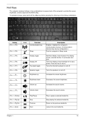
...G3) Off Soft Off (G2/S5) Working (G0/S0) S3 Sleeping State On S4 Sleeping State Power Management All devices in the system are turned off completely. Individual devices such as the CPU and hard disk may be power managed in low power state Discharging • Amber and blinking ...- OS initiated shutdown. Battery full • Amber blinking - All devices in the system are turned off completely. Battery in critical low state • Blue / Amber color off the whole system. CPU set power down VGA suspend PCMCIA suspend Audio...
...G3) Off Soft Off (G2/S5) Working (G0/S0) S3 Sleeping State On S4 Sleeping State Power Management All devices in the system are turned off completely. Individual devices such as the CPU and hard disk may be power managed in low power state Discharging • Amber and blinking ...- OS initiated shutdown. Battery full • Amber blinking - All devices in the system are turned off completely. Battery in critical low state • Blue / Amber color off the whole system. CPU set power down VGA suspend PCMCIA suspend Audio...
Service Guide
Page 56
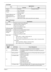
NOTE: Make sure you do the following: 1. Turn off the power to the system and all power and signal cables from the system. Place the system on a flat, stable surface. 46 Chapter 3 Unplug the AC adapter and all peripherals. 2. Yellow for UMA (65W) and blue for discrete (90W). 3. Pre-disassembly Instructions Before proceeding with the disassembly procedure, make sure that you match the AC adapter with the correct model.
NOTE: Make sure you do the following: 1. Turn off the power to the system and all power and signal cables from the system. Place the system on a flat, stable surface. 46 Chapter 3 Unplug the AC adapter and all peripherals. 2. Yellow for UMA (65W) and blue for discrete (90W). 3. Pre-disassembly Instructions Before proceeding with the disassembly procedure, make sure that you match the AC adapter with the correct model.
Service Guide
Page 58
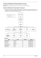
... No. 86.R4F02.002 86.R4F02.007 86.R4F02.002 86.R4F02.002 86.R4F02.007 86.R4F02.005 48 Chapter 3 Discrete Flowchart UMA Flowchart Turn off system and peripherals power Disconnect power and signal cables from the mass produced model. External Modules Disassembly Flowchart The flowchart below gives you a graphic...
... No. 86.R4F02.002 86.R4F02.007 86.R4F02.002 86.R4F02.002 86.R4F02.007 86.R4F02.005 48 Chapter 3 Discrete Flowchart UMA Flowchart Turn off system and peripherals power Disconnect power and signal cables from the mass produced model. External Modules Disassembly Flowchart The flowchart below gives you a graphic...
Service Guide
Page 59
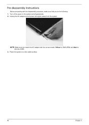
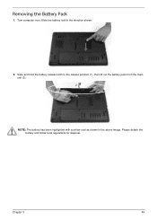
Removing the Battery Pack 1. Please detach the battery and follow local regulations for disposal. Chapter 3 49 Turn computer over. Slide and hold the battery release latch to the release position (1), then lift out the battery pack from the main unit (2). 2 1 NOTE: The battery has been highlighted with a yellow oval as shown in the direction shown. 2. Slide the battery lock in the above image.
Removing the Battery Pack 1. Please detach the battery and follow local regulations for disposal. Chapter 3 49 Turn computer over. Slide and hold the battery release latch to the release position (1), then lift out the battery pack from the main unit (2). 2 1 NOTE: The battery has been highlighted with a yellow oval as shown in the direction shown. 2. Slide the battery lock in the above image.
Service Guide
Page 61
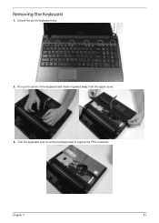
Pry up the center of the keyboard and rotate it upward away from the upper cover. 3. Chapter 3 51 Removing the Keyboard 1. Turn the keyboard over on to the touchpad area to expose the FPC connector. Unlock the six (6) keyboard locks. 2.
Pry up the center of the keyboard and rotate it upward away from the upper cover. 3. Chapter 3 51 Removing the Keyboard 1. Turn the keyboard over on to the touchpad area to expose the FPC connector. Unlock the six (6) keyboard locks. 2.
Service Guide
Page 74
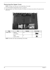
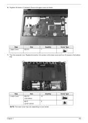
Remove the twelve (12) screws on page 48. 2. Step Lower Cover Size M2.5*8 (red callout) Quantity 12 M2*3 4 (green callout) NOTE: The lower cover may vary in color depending on the model. 1. Screw Type 64 Chapter 3 Removing the Upper Cover NOTE: The upper cover may vary depending on the model. See "External Module Disassembly Process" on the lower cover and four (4) screws from the battery bay. Turn the computer over.
Remove the twelve (12) screws on page 48. 2. Step Lower Cover Size M2.5*8 (red callout) Quantity 12 M2*3 4 (green callout) NOTE: The lower cover may vary in color depending on the model. 1. Screw Type 64 Chapter 3 Removing the Upper Cover NOTE: The upper cover may vary depending on the model. See "External Module Disassembly Process" on the lower cover and four (4) screws from the battery bay. Turn the computer over.
Service Guide
Page 75
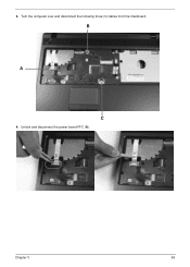
Unlock and disconnect the power board FFC (A). Chapter 3 65 3. B A C 4. Turn the computer over and disconnect the following three (3) cables from the mainboard.
Unlock and disconnect the power board FFC (A). Chapter 3 65 3. B A C 4. Turn the computer over and disconnect the following three (3) cables from the mainboard.
Service Guide
Page 79
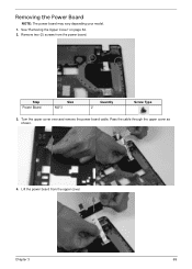
Removing the Power Board NOTE: The power board may vary depending your model. 1. Step Power Board Size M2*3 Quantity 2 Screw Type 3. Pass the cable through the upper cover as shown. 4. Chapter 3 69 Turn the upper cover over and remove the power board cable. Lift the power board from the power board. Remove two (2) screws from the upper cover. See "Removing the Upper Cover" on page 64. 2.
Removing the Power Board NOTE: The power board may vary depending your model. 1. Step Power Board Size M2*3 Quantity 2 Screw Type 3. Pass the cable through the upper cover as shown. 4. Chapter 3 69 Turn the upper cover over and remove the power board cable. Lift the power board from the power board. Remove two (2) screws from the upper cover. See "Removing the Upper Cover" on page 64. 2.
Service Guide
Page 90
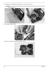
Carefully turn it on a clean, dust-free surface. Disconnect the power cable. 9. Remove the mainboard from the chassis and turn the mainboard over and place it over as it is still connected to the chassis by the power cable. 8. 7. CAUTION: Do not use excessive force when turning the mainboard over . 80 Chapter 3
Carefully turn it on a clean, dust-free surface. Disconnect the power cable. 9. Remove the mainboard from the chassis and turn the mainboard over and place it over as it is still connected to the chassis by the power cable. 8. 7. CAUTION: Do not use excessive force when turning the mainboard over . 80 Chapter 3
Service Guide
Page 140
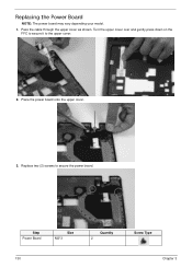
Step Power Board Size M2*3 Quantity 2 130 Screw Type Chapter 3 Pass the cable through the upper cover as shown. Replace two (2) screws to the upper cover. 2. Place the power board onto the upper cover. 3. Replacing the Power Board NOTE: The power board may vary depending your model. 1. Turn the upper cover over and gently press down on the FFC to secure it to secure the power board.
Step Power Board Size M2*3 Quantity 2 130 Screw Type Chapter 3 Pass the cable through the upper cover as shown. Replace two (2) screws to the upper cover. 2. Place the power board onto the upper cover. 3. Replacing the Power Board NOTE: The power board may vary depending your model. 1. Turn the upper cover over and gently press down on the FFC to secure it to secure the power board.
Service Guide
Page 145
6. Step Upper Cover Size M2.5*5 Quantity 7 Screw Type 7. Screw Type Chapter 3 135 Replace the twelve (12) screws on your model. Step Lower Cover Size M2.5*8 (red callout) Quantity 12 M2*3 4 (green callout) NOTE: The lower cover may vary depending on the lower cover and four (4) screws in the battery bay. Replace the seven (7) screws to secure the upper cover as shown. Turn the computer over.
6. Step Upper Cover Size M2.5*5 Quantity 7 Screw Type 7. Screw Type Chapter 3 135 Replace the twelve (12) screws on your model. Step Lower Cover Size M2.5*8 (red callout) Quantity 12 M2*3 4 (green callout) NOTE: The lower cover may vary depending on the lower cover and four (4) screws in the battery bay. Replace the seven (7) screws to secure the upper cover as shown. Turn the computer over.
Service Guide
Page 169
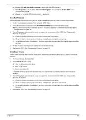
...that the Enable DMA box is identical to the ODD. c. Replace the ODD. Test the drive using other ATA Devices shown if applicable. Turn off the power and remove the cover to inspect the connections to one of the ODDs specified in "Hardware Specifications and Configurations" on the drive...the drive is probably defective and should be read when inserted in the ATAPI Model Name field on the drive, motherboard, and cable connections. Turn off the power and remove the cover to inspect the connections to enter the BIOS Utility. 2. See "Disassembly Process" on page 47. ...
...that the Enable DMA box is identical to the ODD. c. Replace the ODD. Test the drive using other ATA Devices shown if applicable. Turn off the power and remove the cover to inspect the connections to one of the ODDs specified in "Hardware Specifications and Configurations" on the drive...the drive is probably defective and should be read when inserted in the ATAPI Model Name field on the drive, motherboard, and cable connections. Turn off the power and remove the cover to inspect the connections to enter the BIOS Utility. 2. See "Disassembly Process" on page 47. ...


