Service Guide
Page 7
... Features 1 System Block Diagram 6 Discrete Model 6 UMA Model 7 Your Acer Notebook tour 8 Front View 8 Rear View 9 Left View 9 Right ... Configurations 16 System Utilities 29 BIOS Setup Utility 29 Navigating the BIOS Utility 29 Aspire AS5552/AS5552G BIOS 30 Information 30 Main 31 Security 32 Boot 35 Exit 36 ... HDD/BIOS Password Utilities 41 Machine Disassembly and Replacement 45 Disassembly Requirements 45 Pre-disassembly Instructions 46 Disassembly Process 47 External Module Disassembly Process 48 External Modules Disassembly Flowchart 48 Removing the Battery Pack ...
... Features 1 System Block Diagram 6 Discrete Model 6 UMA Model 7 Your Acer Notebook tour 8 Front View 8 Rear View 9 Left View 9 Right ... Configurations 16 System Utilities 29 BIOS Setup Utility 29 Navigating the BIOS Utility 29 Aspire AS5552/AS5552G BIOS 30 Information 30 Main 31 Security 32 Boot 35 Exit 36 ... HDD/BIOS Password Utilities 41 Machine Disassembly and Replacement 45 Disassembly Requirements 45 Pre-disassembly Instructions 46 Disassembly Process 47 External Module Disassembly Process 48 External Modules Disassembly Flowchart 48 Removing the Battery Pack ...
Service Guide
Page 8
... 78 Removing the Thermal Module 82 Removing the CPU 84 Removing the LCD Assembly 85 Removing the DC-IN Assembly 88 LCD Module Disassembly Process 89 LCD Module Disassembly Flowchart 89 Removing the LCD Bezel 90 Removing the Camera Module 91 Removing the Inverter Board (LCD Only 92 Removing the LCD/LED...
... 78 Removing the Thermal Module 82 Removing the CPU 84 Removing the LCD Assembly 85 Removing the DC-IN Assembly 88 LCD Module Disassembly Process 89 LCD Module Disassembly Flowchart 89 Removing the LCD Bezel 90 Removing the Camera Module 91 Removing the Inverter Board (LCD Only 92 Removing the LCD/LED...
Service Guide
Page 55
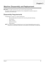
...: The outside housing and color may vary from the mass produced model. During the disassembly process, group the screws with the corresponding components to disassemble the notebook computer for the different components vary in size. Chapter 3 45 Disassembly Requirements To disassemble the computer, you need the following tools: • Wrist grounding strap and conductive...
...: The outside housing and color may vary from the mass produced model. During the disassembly process, group the screws with the corresponding components to disassemble the notebook computer for the different components vary in size. Chapter 3 45 Disassembly Requirements To disassemble the computer, you need the following tools: • Wrist grounding strap and conductive...
Service Guide
Page 56
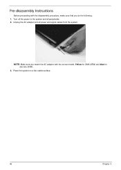
Unplug the AC adapter and all peripherals. 2. NOTE: Make sure you match the AC adapter with the disassembly procedure, make sure that you do the following: 1. Yellow for UMA (65W) and blue for discrete (90W). 3. Pre-disassembly Instructions Before proceeding with the correct model. Turn off the power to the system and all power and signal cables from the system. Place the system on a flat, stable surface. 46 Chapter 3
Unplug the AC adapter and all peripherals. 2. NOTE: Make sure you match the AC adapter with the disassembly procedure, make sure that you do the following: 1. Yellow for UMA (65W) and blue for discrete (90W). 3. Pre-disassembly Instructions Before proceeding with the correct model. Turn off the power to the system and all power and signal cables from the system. Place the system on a flat, stable surface. 46 Chapter 3
Service Guide
Page 57
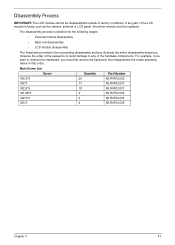
... the following stages: • External module disassembly • Main unit disassembly • LCD module disassembly The flowcharts provided in that order. Observe the order of factory conditions. Disassembly Process IMPORTANT: The LCD module cannot be disassembled outside of the sequence to avoid damage to... remove the mainboard, you must be replaced. The disassembly process is faulty, such as the camera, antenna ...
... the following stages: • External module disassembly • Main unit disassembly • LCD module disassembly The flowcharts provided in that order. Observe the order of factory conditions. Disassembly Process IMPORTANT: The LCD module cannot be disassembled outside of the sequence to avoid damage to... remove the mainboard, you must be replaced. The disassembly process is faulty, such as the camera, antenna ...
Service Guide
Page 58
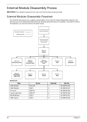
... power Disconnect power and signal cables from the mass produced model. External Modules Disassembly Flowchart The flowchart below gives you a graphic representation of the external module disassembly sequence and instructs you must first remove the switch board. External Module Disassembly Process IMPORTANT: The outside housing and color may vary from system Remove Battery...
... power Disconnect power and signal cables from the mass produced model. External Modules Disassembly Flowchart The flowchart below gives you a graphic representation of the external module disassembly sequence and instructs you must first remove the switch board. External Module Disassembly Process IMPORTANT: The outside housing and color may vary from system Remove Battery...
Service Guide
Page 73
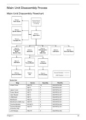
Main Unit Disassembly Process Main Unit Disassembly Flowchart Remove Power Board Remove External Modules before proceeding Remove Speaker Module Remove Touchpad FFC Remove Upper Cover Remove Card Reader Board (Discrete Only) Remove ...
Main Unit Disassembly Process Main Unit Disassembly Flowchart Remove Power Board Remove External Modules before proceeding Remove Speaker Module Remove Touchpad FFC Remove Upper Cover Remove Card Reader Board (Discrete Only) Remove ...
Service Guide
Page 74
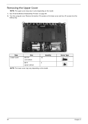
See "External Module Disassembly Process" on the lower cover and four (4) screws from the battery bay. Step Lower Cover Size M2.5*8 (red callout) Quantity 12 M2*3 4 (green callout) NOTE: The lower cover may vary in color depending on the model. 1. Screw Type 64 Chapter 3 Turn the computer over. Removing the Upper Cover NOTE: The upper cover may vary depending on the model. Remove the twelve (12) screws on page 48. 2.
See "External Module Disassembly Process" on the lower cover and four (4) screws from the battery bay. Step Lower Cover Size M2.5*8 (red callout) Quantity 12 M2*3 4 (green callout) NOTE: The lower cover may vary in color depending on the model. 1. Screw Type 64 Chapter 3 Turn the computer over. Removing the Upper Cover NOTE: The upper cover may vary depending on the model. Remove the twelve (12) screws on page 48. 2.
Service Guide
Page 99
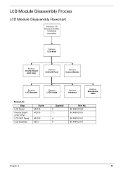
LCD Module Disassembly Process LCD Module Disassembly Flowchart Remove LCD Module from Main Unit before proceeding Remove LCD Bezel Remove Inverter Board (LCD Only) Remove LCD/LED Panel Remove Camera Module Remove LCD Brackets Remove LVDS Cable Remove Antennas Remove Microphone Cable Screw List Step LCD Bezel Inverter Board (LCD Only) LCD/LED Panel LCD Brackets Screw M2.5*6 M2.5*5 M2.5*5 M2*3 Quantity 2 1 4 6 Part No. 86.R4F02.003 86.R4F02.001 86.R4F02.001 86.R4F02.007 Chapter 3 89
LCD Module Disassembly Process LCD Module Disassembly Flowchart Remove LCD Module from Main Unit before proceeding Remove LCD Bezel Remove Inverter Board (LCD Only) Remove LCD/LED Panel Remove Camera Module Remove LCD Brackets Remove LVDS Cable Remove Antennas Remove Microphone Cable Screw List Step LCD Bezel Inverter Board (LCD Only) LCD/LED Panel LCD Brackets Screw M2.5*6 M2.5*5 M2.5*5 M2*3 Quantity 2 1 4 6 Part No. 86.R4F02.003 86.R4F02.001 86.R4F02.001 86.R4F02.007 Chapter 3 89
Service Guide
Page 161
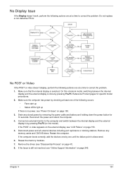
... 47). 8. If the Issue is selected. Connect an external monitor to correct the problem. 1. If the POST or video appears on the external display, see "Disassembly Process" on page 153. 5. Restart the computer. Make sure that the internal display is still not resolved, see "Power On Issue" on page 245. On...
... 47). 8. If the Issue is selected. Connect an external monitor to correct the problem. 1. If the POST or video appears on the external display, see "Disassembly Process" on page 153. 5. Restart the computer. Make sure that the internal display is still not resolved, see "Power On Issue" on page 245. On...
Service Guide
Page 162
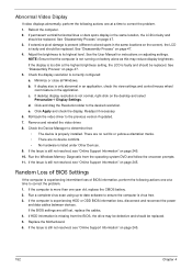
...(different colored spots in the same locations on battery alone as this may be defective and should be replaced. 5. See "Disassembly Process" on adjusting settings. Minimize or close all Windows. If desktop display resolution is properly installed. There are no red Xs...• There are still lost, replace the cables. 4. Run the Windows Memory Diagnostic from the BIOS, the drive may reduce display brightness. See "Disassembly Process" on the desktop and select Personalize´ Display Settings. NOTE: Ensure that : • The device is not normal, right-click on page...
...(different colored spots in the same locations on battery alone as this may be defective and should be replaced. 5. See "Disassembly Process" on adjusting settings. Minimize or close all Windows. If desktop display resolution is properly installed. There are no red Xs...• There are still lost, replace the cables. 4. Run the Windows Memory Diagnostic from the BIOS, the drive may reduce display brightness. See "Disassembly Process" on the desktop and select Personalize´ Display Settings. NOTE: Ensure that : • The device is not normal, right-click on page...
Service Guide
Page 166
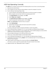
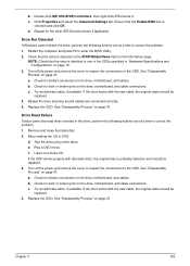
... Windows Memory Diagnostic Tool. For more information see Windows Help and Support. 9. Remove any key to start to resolve the problem. 4. Replace the HDD. See "Disassembly Process" on the HDD and ODD are required. f. NOTE: Click Load Drivers if controller drives are set as the first boot device on the Boot...
... Windows Memory Diagnostic Tool. For more information see Windows Help and Support. 9. Remove any key to start to resolve the problem. 4. Replace the HDD. See "Disassembly Process" on the HDD and ODD are required. f. NOTE: Click Load Drivers if controller drives are set as the first boot device on the Boot...
Service Guide
Page 169
...the drive is probably defective and should be read when inserted in the ATAPI Model Name field on the drive, motherboard, and cable connections. See "Disassembly Process" on page 47. Reseat the drive ensuring and all cables are connected correctly. 5. Remove and clean the failed disc. 2. c. b. d....computer and press F2 to the ODD. Turn off the power and remove the cover to inspect the connections to enter the BIOS Utility. 2. See "Disassembly Process" on page 16. 3. Chapter 4 159 Replace the ODD. Test the drive using other ATA Devices shown if applicable. e. Play a DVD...
...the drive is probably defective and should be read when inserted in the ATAPI Model Name field on the drive, motherboard, and cable connections. See "Disassembly Process" on page 47. Reseat the drive ensuring and all cables are connected correctly. 5. Remove and clean the failed disc. 2. c. b. d....computer and press F2 to the ODD. Turn off the power and remove the cover to inspect the connections to enter the BIOS Utility. 2. See "Disassembly Process" on page 16. 3. Chapter 4 159 Replace the ODD. Test the drive using other ATA Devices shown if applicable. e. Play a DVD...
Service Guide
Page 257
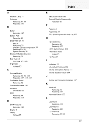
... Problems 150 computer on indicator 11 CPU Removing 84 Replacing 116 D DIMM Modules Replacing 140 Display 6 display hotkeys 15 Index E EasyTouch Failure 160 External Module Disassembly Flowchart 48 F Features 1 Flash Utility 37 FRU (Field Replaceable Unit) List 177 H Hard Disk Drive Removing 60 Replacing 137 HDTV Switch Failure 161 Hibernation mode...
... Problems 150 computer on indicator 11 CPU Removing 84 Replacing 116 D DIMM Modules Replacing 140 Display 6 display hotkeys 15 Index E EasyTouch Failure 160 External Module Disassembly Flowchart 48 F Features 1 Flash Utility 37 FRU (Field Replaceable Unit) List 177 H Hard Disk Drive Removing 60 Replacing 137 HDTV Switch Failure 161 Hibernation mode...
Service Guide
Page 258
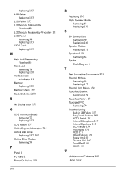
... 89 LCD Module Reassembly Procedure 101 LCD Panel Removing 94 Replacing 103 LVDS Cable Replacing 105 M Main Unit Disassembly Flowchart 63 Mainboard Removing 78 Replacing 120 media access on indicator 11 Memory Replacing 140 Memory Check 150 Model Definition 200 N No Display Issue 151 O ...
... 89 LCD Module Reassembly Procedure 101 LCD Panel Removing 94 Replacing 103 LVDS Cable Replacing 105 M Main Unit Disassembly Flowchart 63 Mainboard Removing 78 Replacing 120 media access on indicator 11 Memory Replacing 140 Memory Check 150 Model Definition 200 N No Display Issue 151 O ...


