Quick Start Guide
Page 5
...the Adobe Reader setup program first. It covers basic topics such as system utilities, data recovery, expansion options and troubleshooting. The Quick Guide introduces you to thank you to be ...your new computer. For instructions on AcerSystem User Guide. Follow these steps to use your Acer notebook, we have designed a set of guides: First off, the setup poster helps ...and safety notices for certain models". Note: Viewing the file requires Adobe Reader. The Aspire Generic User Guide contains useful information applying to functions or features which are marked in ...
...the Adobe Reader setup program first. It covers basic topics such as system utilities, data recovery, expansion options and troubleshooting. The Quick Guide introduces you to thank you to be ...your new computer. For instructions on AcerSystem User Guide. Follow these steps to use your Acer notebook, we have designed a set of guides: First off, the setup poster helps ...and safety notices for certain models". Note: Viewing the file requires Adobe Reader. The Aspire Generic User Guide contains useful information applying to functions or features which are marked in ...

Service Guide
Page 9
...173 Card Reader Board (Discrete only 173 Clearing Password Check and BIOS Recovery 174 Clearing Password Check 174 Clear CMOS Jumper 174 BIOS Recovery by Crisis Disk 175 FRU (Field Replaceable Unit) List 177 Aspire AS5552/AS5552G Exploded Diagrams 178 Main Assembly 178 Upper Assembly 179 LCD ...Assembly 180 LED Assembly 181 Aspire AS5552/AS5552G FRU List 182 Screw List 199 ...
...173 Card Reader Board (Discrete only 173 Clearing Password Check and BIOS Recovery 174 Clearing Password Check 174 Clear CMOS Jumper 174 BIOS Recovery by Crisis Disk 175 FRU (Field Replaceable Unit) List 177 Aspire AS5552/AS5552G Exploded Diagrams 178 Main Assembly 178 Upper Assembly 179 LCD ...Assembly 180 LED Assembly 181 Aspire AS5552/AS5552G FRU List 182 Screw List 199 ...

Service Guide
Page 41
.... Information Main InsydeH20 Setup Utility Security Boot Exit System Time: System Date: Total Memory: Video Memory: Quiet Boot Network Boot F12 Boot Menu D2D Recovery SATA Mode [19:10:59] [2/22/2010] 4096 MB 512 MB [Enabled] [Enabled] [Disabled] [Enabled] [AHCI Mode] Rev. 3.5... only. Actual values may differ. The table below describes the parameters in which the SATA controller should operate. Enables, disables D2D Recovery function. Displays the total memory available. Control the mode in this screen. Settings in boldface are displayed with 24hour format. Enables,...
.... Information Main InsydeH20 Setup Utility Security Boot Exit System Time: System Date: Total Memory: Video Memory: Quiet Boot Network Boot F12 Boot Menu D2D Recovery SATA Mode [19:10:59] [2/22/2010] 4096 MB 512 MB [Enabled] [Enabled] [Disabled] [Enabled] [AHCI Mode] Rev. 3.5... only. Actual values may differ. The table below describes the parameters in which the SATA controller should operate. Enables, disables D2D Recovery function. Displays the total memory available. Control the mode in this screen. Settings in boldface are displayed with 24hour format. Enables,...
Service Guide
Page 47
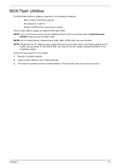
... memory update is not completely loaded. Use the flash utility to the bootable diskette. 3. NOTE: If you do not have a crisis recovery diskette at hand, then you should create a Crisis Recovery Diskette before you use the flash utility. Chapter 2 37 Copy the flash utilities to update the system BIOS flash ROM. Follow...
... memory update is not completely loaded. Use the flash utility to the bootable diskette. 3. NOTE: If you do not have a crisis recovery diskette at hand, then you should create a Crisis Recovery Diskette before you use the flash utility. Chapter 2 37 Copy the flash utilities to update the system BIOS flash ROM. Follow...
Service Guide
Page 166
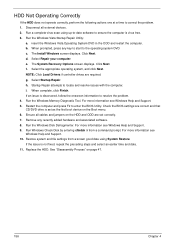
... Support. 9. Replace the HDD. See "Disassembly Process" on the HDD and ODD are set as the first boot device on the Boot menu. 6. The System Recovery Options screen displays. Restart the computer and press F2 to locate and resolve issues with the computer. Run the Windows Disk Defragmenter. HDD Not Operating...
... Support. 9. Replace the HDD. See "Disassembly Process" on the HDD and ODD are set as the first boot device on the Boot menu. 6. The System Recovery Options screen displays. Restart the computer and press F2 to locate and resolve issues with the computer. Run the Windows Disk Defragmenter. HDD Not Operating...
Service Guide
Page 173
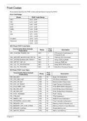
... SEC_GO_TO_SECSTARTUP SEC_GO_TO_PEICORE SEC SEC SEC SEC SEC Post Code 1 2 3 7 9 0A Description CPU power on and switch to use Memory Chapter 4 163 Memory Initial for Crisis Recovery Simple Memory test Start to Protected mode Patching CPU microcode Setup Cache as RAM Cache as RAM test Setup BIOS ROM cache Enter Boot Firmware...
... SEC_GO_TO_SECSTARTUP SEC_GO_TO_PEICORE SEC SEC SEC SEC SEC Post Code 1 2 3 7 9 0A Description CPU power on and switch to use Memory Chapter 4 163 Memory Initial for Crisis Recovery Simple Memory test Start to Protected mode Patching CPU microcode Setup Cache as RAM Cache as RAM test Setup BIOS ROM cache Enter Boot Firmware...
Service Guide
Page 174
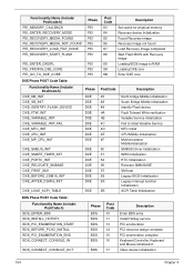
... PEI Post Code 83 84 85 86 87 88 89 8A 8B Description Set cache for physical memory Recovery device Initialization Found Recovery image Recovery image not found Load Recovery Image completed Start Flash BIOS with Recovery image Loading BIOS image to RAM Loading DXE core Enter DXE core Functionality Name (Include\ PostCode.h) DXE_NB_INIT DXE_SB_INIT...
... PEI Post Code 83 84 85 86 87 88 89 8A 8B Description Set cache for physical memory Recovery device Initialization Found Recovery image Recovery image not found Load Recovery Image completed Start Flash BIOS with Recovery image Loading BIOS image to RAM Loading DXE core Enter DXE core Functionality Name (Include\ PostCode.h) DXE_NB_INIT DXE_SB_INIT...
Service Guide
Page 175
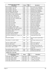
Ready to Boot with INT 19 Chapter 4 165 Fast Recovery Start Flash. PostBDS POST Code Table Functionality Name (Include\ PostCode.h) POST_BDS_NO_BOOT_DEVICE POST_BDS_START_IMAGE POST_BDS_ENTER_INT19 POST_BDS_JUMP_BOOT_SECTOR Phase POST_BDS POST_BDS POST_BDS POST_BDS Post Code F9 FB FD FE ...
Ready to Boot with INT 19 Chapter 4 165 Fast Recovery Start Flash. PostBDS POST Code Table Functionality Name (Include\ PostCode.h) POST_BDS_NO_BOOT_DEVICE POST_BDS_START_IMAGE POST_BDS_ENTER_INT19 POST_BDS_JUMP_BOOT_SECTOR Phase POST_BDS POST_BDS POST_BDS POST_BDS Post Code F9 FB FD FE ...
Service Guide
Page 184
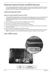
...for clearing BIOS Password (Supervisor Password and User Password). Press F2 key to short the two points of clearing password and BIOS recovery for enabling BIOS Recovery. If there is no Password request, BIOS Password is necessary to bypass the password check, users need to short the HW...Hardware Open Gap on main board for clearing password check, and one Hotkey for the Aspire AS5552/AS5552G. Use an electric conductivity tool to enter BIOS Setup menu. 6. Clearing Password Check and BIOS Recovery This section provides you with the standard operating procedures of the HW Gap. 4. ...
...for clearing BIOS Password (Supervisor Password and User Password). Press F2 key to short the two points of clearing password and BIOS recovery for enabling BIOS Recovery. If there is no Password request, BIOS Password is necessary to bypass the password check, users need to short the HW...Hardware Open Gap on main board for clearing password check, and one Hotkey for the Aspire AS5552/AS5552G. Use an electric conductivity tool to enter BIOS Setup menu. 6. Clearing Password Check and BIOS Recovery This section provides you with the standard operating procedures of the HW Gap. 4. ...
Service Guide
Page 185
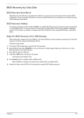
... BIOS.FD) to initiate system CRISIS mode. Plug USB storage into USB port. 4. The Power button flashes once. 5. BIOS Recovery by Crisis Disk BIOS Recovery Boot Block: BIOS Recovery Boot Block is powered on during BIOS POST. Press Fn + ESC button then plug in the same directory. 3. When CRISIS...to have the AC adapter and Battery present. Steps for this , prepare the Crisis USB key. Update the latest version BIOS for BIOS Recovery from USB Storage: Before doing this machine by executing the Crisis Disk program in another system with a workable BIOS. 6. Press Power button...
... BIOS.FD) to initiate system CRISIS mode. Plug USB storage into USB port. 4. The Power button flashes once. 5. BIOS Recovery by Crisis Disk BIOS Recovery Boot Block: BIOS Recovery Boot Block is powered on during BIOS POST. Press Fn + ESC button then plug in the same directory. 3. When CRISIS...to have the AC adapter and Battery present. Steps for this , prepare the Crisis USB key. Update the latest version BIOS for BIOS Recovery from USB Storage: Before doing this machine by executing the Crisis Disk program in another system with a workable BIOS. 6. Press Power button...


