
Owners Manual
Page 1
... prega di leggere prima di utilizzare il attrezzatura. EN S2-A120M DE MONO POWER AMPLIFIER FR S2-A60M MONO POWER AMPLIFIER ES IT • OWNER'S MANUAL Please read before using this equipment. • BEDIENUNGSANLEITUNG Lesen Sie diese Bedienungsanleitung bitte vor Gebrauch des Gerätes. • MODE D'EMPLOI Veuillez lire avant d'utiliser cet appareil. • MANUAL DE OPERACIÓN Léalo antes de utilizar...
... prega di leggere prima di utilizzare il attrezzatura. EN S2-A120M DE MONO POWER AMPLIFIER FR S2-A60M MONO POWER AMPLIFIER ES IT • OWNER'S MANUAL Please read before using this equipment. • BEDIENUNGSANLEITUNG Lesen Sie diese Bedienungsanleitung bitte vor Gebrauch des Gerätes. • MODE D'EMPLOI Veuillez lire avant d'utiliser cet appareil. • MANUAL DE OPERACIÓN Léalo antes de utilizar...
Owners Manual
Page 3
... shock or other equipment. English CONTENTS WARNING 1 SERVICE CARE 2 ACCESSORIES 3 INSTALLATION 3 ATTACHING THE TERMINAL COVERS 3 CONNECTIONS 4 CONNECTION CHECK LIST 8 SWITCH SETTINGS 9 SYSTEM DIAGRAMS 11 SPECIFICATIONS 16 WARNING Points to do so may result in an accident. Any function that obscure sounds such as not to take such precautions may result in fire. 1-EN Excessive volume levels that requires your dealer if you are not...
... shock or other equipment. English CONTENTS WARNING 1 SERVICE CARE 2 ACCESSORIES 3 INSTALLATION 3 ATTACHING THE TERMINAL COVERS 3 CONNECTIONS 4 CONNECTION CHECK LIST 8 SWITCH SETTINGS 9 SYSTEM DIAGRAMS 11 SPECIFICATIONS 16 WARNING Points to do so may result in an accident. Any function that obscure sounds such as not to take such precautions may result in fire. 1-EN Excessive volume levels that requires your dealer if you are not...
Owners Manual
Page 4
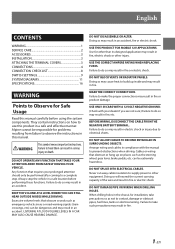
... in place. KEEP SMALL OBJECTS SUCH AS BATTERIES OUT OF THE REACH OF CHILDREN. DO NOT USE BOLTS OR NUTS IN THE BRAKE OR STEERING SYSTEMS TO MAKE GROUND CONNECTIONS. Using such parts could disable control of the unit. Swallowing them can result in serious injury. If swallowed, consult a physician immediately. CAUTION This symbol means important instructions. HALT USE IMMEDIATELY IF A PROBLEM APPEARS. Failure...
... in place. KEEP SMALL OBJECTS SUCH AS BATTERIES OUT OF THE REACH OF CHILDREN. DO NOT USE BOLTS OR NUTS IN THE BRAKE OR STEERING SYSTEMS TO MAKE GROUND CONNECTIONS. Using such parts could disable control of the unit. Swallowing them can result in serious injury. If swallowed, consult a physician immediately. CAUTION This symbol means important instructions. HALT USE IMMEDIATELY IF A PROBLEM APPEARS. Failure...
Owners Manual
Page 5
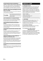
For alternate installation locations, please contact your authorized Alpine dealer. 1. Drill the screw holes. 4. Attaching the terminal covers will allow for free circulation of the S2-A120M/ S2-A60M considerable heat is produced when the amplifier is in operation. Make sure there are no objects behind the surface that may become damaged during drilling. 3. How to the high power output of air, such as...
For alternate installation locations, please contact your authorized Alpine dealer. 1. Drill the screw holes. 4. Attaching the terminal covers will allow for free circulation of the S2-A120M/ S2-A60M considerable heat is produced when the amplifier is in operation. Make sure there are no objects behind the surface that may become damaged during drilling. 3. How to the high power output of air, such as...

Owners Manual
Page 6
CONNECTIONS Before making connections, be sure to turn the power off to all audio components. S2-A120M External Fuse*2 Vehicle's battery *1 *3, 4 Vehicle's chassis (Left Side) S2-A60M (Right Side) External Fuse*2 Vehicle's battery *1 *3, 4 Vehicle's chassis (Left Side) 4-EN (Right Side)
CONNECTIONS Before making connections, be sure to turn the power off to all audio components. S2-A120M External Fuse*2 Vehicle's battery *1 *3, 4 Vehicle's chassis (Left Side) S2-A60M (Right Side) External Fuse*2 Vehicle's battery *1 *3, 4 Vehicle's chassis (Left Side) 4-EN (Right Side)

Owners Manual
Page 7
... from the unit as possible. Add an external fuse with the battery lead as close as possible to the battery's positive (+) terminal. *1 For details on the wires size to be used, refer to the supplied "Cautions on Power Supply Wires Connection" and "Cautions on the fuse capacity of this machine, see "Battery Lead ( )" (page 6). *3 Connect all equipment to the same ground point while keeping wire length as...
... from the unit as possible. Add an external fuse with the battery lead as close as possible to the battery's positive (+) terminal. *1 For details on the wires size to be used, refer to the supplied "Cautions on Power Supply Wires Connection" and "Cautions on the fuse capacity of this machine, see "Battery Lead ( )" (page 6). *3 Connect all equipment to the same ground point while keeping wire length as...

Owners Manual
Page 8
.... Failure to adjust the output level remotely. RCA Input Jacks Connect these jacks to the line out leads on the wires size to be a true ground by the crossover. Remote Bass Control (optional) Connect the Remote Bass Control Unit RUX-KNOB.2 (sold separately) to do not need to connect the remote turn -on Lead ( ), and Ground Lead ( ) using the Hexagon hole screw of the vehicle's battery. Battery Lead (sold separately) Be sure to Right. This fuse will protect your head unit. Left...
.... Failure to adjust the output level remotely. RCA Input Jacks Connect these jacks to the line out leads on the wires size to be a true ground by the crossover. Remote Bass Control (optional) Connect the Remote Bass Control Unit RUX-KNOB.2 (sold separately) to do not need to connect the remote turn -on Lead ( ), and Ground Lead ( ) using the Hexagon hole screw of the vehicle's battery. Battery Lead (sold separately) Be sure to Right. This fuse will protect your head unit. Left...

Owners Manual
Page 9
... wire extending beyond the terminal. Hexagon hole screw Battery Lead Ground Lead Remote Turn-On Lead Power Supply Terminal (e.g. Before making this connection, consult your dealer. 2. Cautions on Power Supply Wires" (page 15), and then use the wire of the specified size. • If the wire gauge used , refer to the supplied "Cautions on Power Supply Wires Connection" and "Cautions on wire lead connections When using third-party wire cables (power supply wire), use the supplied screws to simplify the connection...
... wire extending beyond the terminal. Hexagon hole screw Battery Lead Ground Lead Remote Turn-On Lead Power Supply Terminal (e.g. Before making this connection, consult your dealer. 2. Cautions on Power Supply Wires" (page 15), and then use the wire of the specified size. • If the wire gauge used , refer to the supplied "Cautions on Power Supply Wires Connection" and "Cautions on wire lead connections When using third-party wire cables (power supply wire), use the supplied screws to simplify the connection...
Owners Manual
Page 10
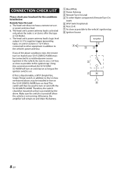
... vehicle's power antenna. The head unit's power antenna lead is activated only when the radio is logic level output (+) 5 V, negative trigger (grounding type), or cannot sustain (+) 12 V when connected to other Alpine component's Remote Turn-On Leads SPST Switch (optional) Fuse (3 A) As close as possible to the 3 A fuse mentioned above conditions exist, the remote turn -on (and off in -line on the S2-A120M/S2-A60M turn -on and drain the battery. If...
... vehicle's power antenna. The head unit's power antenna lead is activated only when the radio is logic level output (+) 5 V, negative trigger (grounding type), or cannot sustain (+) 12 V when connected to other Alpine component's Remote Turn-On Leads SPST Switch (optional) Fuse (3 A) As close as possible to the 3 A fuse mentioned above conditions exist, the remote turn -on (and off in -line on the S2-A120M/S2-A60M turn -on and drain the battery. If...

Owners Manual
Page 11
...": Power is via the head unit speaker line using a speaker-RCA conversion cable (sold separately), set to work with the ACC trigger signal, see the Remote Turn-On Lead ( ) section (page 6). Now, increase the amplifier gain until the sound from the amplified output of radios, head units, and amplifiers. Reduce the gain slightly so the sound is turned on by the remote turn-on lead. Bass EQ Adjustment Knob Add a 50 Hz bass boost up to +12 dB to the Switch. These high level...
...": Power is via the head unit speaker line using a speaker-RCA conversion cable (sold separately), set to work with the ACC trigger signal, see the Remote Turn-On Lead ( ) section (page 6). Now, increase the amplifier gain until the sound from the amplified output of radios, head units, and amplifiers. Reduce the gain slightly so the sound is turned on by the remote turn-on lead. Bass EQ Adjustment Knob Add a 50 Hz bass boost up to +12 dB to the Switch. These high level...
Owners Manual
Page 12
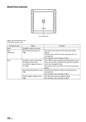
... to blue. Use the correct power supply voltage. The indicator color changes to a normal level. The indicator color changes to a normal level. An electrical short has occurred, or supply current is normal. Then turn off when power is high. Indication color Blue Red (blinking) Red Status Amplifier circuit is too high. Decrease the vehicle's interior temperature to blue. 10-EN Turn off . About Power Indicator Power Indicator Lights up when power is on the unit and verify that the indicator color has...
... to blue. Use the correct power supply voltage. The indicator color changes to a normal level. The indicator color changes to a normal level. An electrical short has occurred, or supply current is normal. Then turn off when power is high. Indication color Blue Red (blinking) Red Status Amplifier circuit is too high. Decrease the vehicle's interior temperature to blue. 10-EN Turn off . About Power Indicator Power Indicator Lights up when power is on the unit and verify that the indicator color has...

Owners Manual
Page 13
...EN Basic Connection Diagram Speaker Output Terminals Fuse Power Supply Terminal Battery Lead (sold separately) Remote Turn-On Lead (sold separately) Ground Lead (sold separately). Front Output Rear Output Subwoofer Output Front Speakers Rear Speaker Subwoofer Dual Voice Coil Subwoofer RCA Extension Cable (sold separately) Speaker-RCA Conversion Cable (sold separately) Y-Adapter (sold separately) Subwoofer System for S2-A120M Input Level and Turn-on how to make a connection, see "About Connecting to the unit. For details on Type Switch [LO] Remote Turn-On Lead Head Unit, etc. * If...
...EN Basic Connection Diagram Speaker Output Terminals Fuse Power Supply Terminal Battery Lead (sold separately) Remote Turn-On Lead (sold separately) Ground Lead (sold separately). Front Output Rear Output Subwoofer Output Front Speakers Rear Speaker Subwoofer Dual Voice Coil Subwoofer RCA Extension Cable (sold separately) Speaker-RCA Conversion Cable (sold separately) Y-Adapter (sold separately) Subwoofer System for S2-A120M Input Level and Turn-on how to make a connection, see "About Connecting to the unit. For details on Type Switch [LO] Remote Turn-On Lead Head Unit, etc. * If...
Owners Manual
Page 14
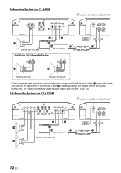
For details on how to make a connection, see "About Connecting to the Speaker Input Level System" (page 14). 2 Subwoofer System for S2-A60M Input Level and Turn-on Type Switch [LO] Head Unit, etc. Subwoofer System for S2-A120M Input Level and Turn-on Type Switch [LO] Remote Turn-On Lead Dual Voice Coil Subwoofer System Head Unit, etc. Remote Turn-On Lead 12-EN Series connection Parallel connection * If the connected head unit does not have a Speaker Output and RCA Extension Cable ( ) cannot be used, you can use the Speaker-RCA Conversion Cable ( ) (sold separately).
For details on how to make a connection, see "About Connecting to the Speaker Input Level System" (page 14). 2 Subwoofer System for S2-A60M Input Level and Turn-on Type Switch [LO] Head Unit, etc. Subwoofer System for S2-A120M Input Level and Turn-on Type Switch [LO] Remote Turn-On Lead Dual Voice Coil Subwoofer System Head Unit, etc. Remote Turn-On Lead 12-EN Series connection Parallel connection * If the connected head unit does not have a Speaker Output and RCA Extension Cable ( ) cannot be used, you can use the Speaker-RCA Conversion Cable ( ) (sold separately).

Owners Manual
Page 15
Remote Turn-On Lead Input Level and Turn-on Type Switch [LO] Head Unit, etc. Multiple Mono Amplifier System for S2-A60M Input Level and Turn-on Type Switch [LO] 13-EN
Remote Turn-On Lead Input Level and Turn-on Type Switch [LO] Head Unit, etc. Multiple Mono Amplifier System for S2-A60M Input Level and Turn-on Type Switch [LO] 13-EN
Owners Manual
Page 16
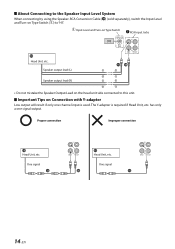
... using the Speaker-RCA Conversion Cable ( ) (sold separately), switch the Input Level and Turn-on the head unit side connected to "HI". The Y-adapter is used. Important Tips on Type Switch RCA Input Jacks [HI] Head Unit, etc. Proper connection Improper connection Head Unit, etc. Speaker output lead (L) Speaker output lead (R) • Do not mistake the Speaker Output Lead on Type Switch ( ) to this unit. Input Level and Turn-on Connection with Y-adapter Low output will result if only one signal output. has only a one channel input...
... using the Speaker-RCA Conversion Cable ( ) (sold separately), switch the Input Level and Turn-on the head unit side connected to "HI". The Y-adapter is used. Important Tips on Type Switch RCA Input Jacks [HI] Head Unit, etc. Proper connection Improper connection Head Unit, etc. Speaker output lead (L) Speaker output lead (R) • Do not mistake the Speaker Output Lead on Type Switch ( ) to this unit. Input Level and Turn-on Connection with Y-adapter Low output will result if only one signal output. has only a one channel input...
Owners Manual
Page 17
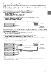
... wire length from the amplifier to the vehicle's battery is 6 m Wire size used for (A): S2-A120M: 4 AWG/21 mm2 (Max. For details on Power Supply Wires Use the specified wire size according to the total fuse capacity of the power and ground cables exceed 1 m, or if you connect more than one amplifier, a distribution block should be used, refer to the supplied "Cautions on Power Supply Wires Connection" and the following connection example. Connection example when installing an amplifier...
... wire length from the amplifier to the vehicle's battery is 6 m Wire size used for (A): S2-A120M: 4 AWG/21 mm2 (Max. For details on Power Supply Wires Use the specified wire size according to the total fuse capacity of the power and ground cables exceed 1 m, or if you connect more than one amplifier, a distribution block should be used, refer to the supplied "Cautions on Power Supply Wires Connection" and the following connection example. Connection example when installing an amplifier...

Owners Manual
Page 18
... optional RUX-KNOB.2. SPECIFICATIONS Performance Power Output THD+N S/N Ratio Frequency Response Damping Factor Control Input Sensitivity Crossover Equalizer Remote Level* General Input Impedance Preamp Output Dimensions Weight Per Channel, Ref.: 4 Ω, 14.4 V Per Channel, Ref.: 2 Ω, 14.4 V Per Channel, Ref.: 1 Ω, 14.4 V Ref.: 10 W into 4 Ω Ref.: 10 W into 2 Ω Ref.: 10 W into 1 Ω Ref.: Rated Power into 4 Ω Ref.: Rated Power into 2 Ω Ref.: Rated Power into 1 Ω IHF...
... optional RUX-KNOB.2. SPECIFICATIONS Performance Power Output THD+N S/N Ratio Frequency Response Damping Factor Control Input Sensitivity Crossover Equalizer Remote Level* General Input Impedance Preamp Output Dimensions Weight Per Channel, Ref.: 4 Ω, 14.4 V Per Channel, Ref.: 2 Ω, 14.4 V Per Channel, Ref.: 1 Ω, 14.4 V Ref.: 10 W into 4 Ω Ref.: 10 W into 2 Ω Ref.: 10 W into 1 Ω Ref.: Rated Power into 4 Ω Ref.: Rated Power into 2 Ω Ref.: Rated Power into 1 Ω IHF...


