
Use and Care
Page 2
... 10 Make Electrical Connections for In-Line Blower Motor System 11 Make Electrical Power Supply Connection to Hood Liner 12 Complete Installation and Check Operation 13 RANGE HOOD USE 14 Range Hood Controls 14 RANGE HOOD CARE 15 Cleaning 15 WIRING DIAGRAM 16 ASSISTANCE OR SERVICE 17 In the U.S.A 17 In Canada...DE LA HOTTE 32 Nettoyage 32 SCHÉMA DE CÂBLAGE 33 ASSISTANCE OU SERVICE 34 Au Canada 34 Accessoires 34 GARANTIE 35 RANGE HOOD SAFETY Your safety and the safety of injury, and tell you what the potential hazard is the safety alert symbol. These words mean: ...
... 10 Make Electrical Connections for In-Line Blower Motor System 11 Make Electrical Power Supply Connection to Hood Liner 12 Complete Installation and Check Operation 13 RANGE HOOD USE 14 Range Hood Controls 14 RANGE HOOD CARE 15 Cleaning 15 WIRING DIAGRAM 16 ASSISTANCE OR SERVICE 17 In the U.S.A 17 In Canada...DE LA HOTTE 32 Nettoyage 32 SCHÉMA DE CÂBLAGE 33 ASSISTANCE OU SERVICE 34 Au Canada 34 Accessoires 34 GARANTIE 35 RANGE HOOD SAFETY Your safety and the safety of injury, and tell you what the potential hazard is the safety alert symbol. These words mean: ...

Use and Care
Page 3
..., OR INJURY TO PERSONS, OBSERVE THE FOLLOWING: ■ Use this fan with any fan with a close fitting lid, cookie sheet, or metal tray, then turn hood ON when cooking at high heat or when flambeing food (i.e. If you have a class ABC extinguisher, and you already know you may ignite. Discard fan...
..., OR INJURY TO PERSONS, OBSERVE THE FOLLOWING: ■ Use this fan with any fan with a close fitting lid, cookie sheet, or metal tray, then turn hood ON when cooking at high heat or when flambeing food (i.e. If you have a class ABC extinguisher, and you already know you may ignite. Discard fan...
Use and Care
Page 4
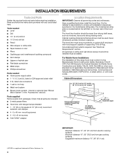
.... Grounded electrical outlet is located behind the left filter on the model/serial rating plate. Check that are included. ■ 3 metal grease filters ■ Hood liner with damper. ■ 4 - 5 x 45 mm mounting screws ■ 4 - 4.2 x 8 mm screws ■ T-20 TORX®†...(121.9 cm) for Manufactured Home Installation 1982 (Manufactured Home Sites, Communities and Setups) ANSI A225.1/NFPA 501A, or latest edition, or with hood support capable of Saturn Fasteners, Inc. 4 Suggested maximum distance "X": 36" (91.4 cm). †®TORX is the installer's responsibility to...
.... Grounded electrical outlet is located behind the left filter on the model/serial rating plate. Check that are included. ■ 3 metal grease filters ■ Hood liner with damper. ■ 4 - 5 x 45 mm mounting screws ■ 4 - 4.2 x 8 mm screws ■ T-20 TORX®†...(121.9 cm) for Manufactured Home Installation 1982 (Manufactured Home Sites, Communities and Setups) ANSI A225.1/NFPA 501A, or latest edition, or with hood support capable of Saturn Fasteners, Inc. 4 Suggested maximum distance "X": 36" (91.4 cm). †®TORX is the installer's responsibility to...

Use and Care
Page 5
... attic or other enclosed area. ■ Do not use of elbows should be as close as part of the thermal break. Consult your area. The hood exhaust opening around the cap. Vent system can terminate either through the wall, a 90° elbow is needed . To vent through the roof or wall...
... attic or other enclosed area. ■ Do not use of elbows should be as close as part of the thermal break. Consult your area. The hood exhaust opening around the cap. Vent system can terminate either through the wall, a 90° elbow is needed . To vent through the roof or wall...

Use and Care
Page 6
... and industry accepted wiring practices. ■ Wire sizes and connections must conform to trusses. mount to cross-members tied to the requirements of the range hood. ■ Wire sizes must conform with National Electrical Code, ANSI/NFPA 70 (latest edition), or CSA Standards C22.1-94, Canadian Electrical Code, Part 1 and C22...
... and industry accepted wiring practices. ■ Wire sizes and connections must conform to trusses. mount to cross-members tied to the requirements of the range hood. ■ Wire sizes must conform with National Electrical Code, ANSI/NFPA 70 (latest edition), or CSA Standards C22.1-94, Canadian Electrical Code, Part 1 and C22...

Use and Care
Page 7
... B C D G E F A. Place covering over that surface. Using 2 or more people to use: roof or wall exhaust. 3. Install the vent system before hood is installed. 3. See the "Venting Requirements" section. 2. Remove terminal box cover and set aside. 7. Using a ¹⁄₈" (3 mm) drill bit, ... surface for the vent system. INSTALLATION INSTRUCTIONS Prepare Location ■ It is recommended that the vent system be installed before installing the range hood. Wall B. Drill a 1¹⁄₄" (3.2 cm) hole at this location. 4. Remove knockout from the top of 36" (...
... B C D G E F A. Place covering over that surface. Using 2 or more people to use: roof or wall exhaust. 3. Install the vent system before hood is installed. 3. See the "Venting Requirements" section. 2. Remove terminal box cover and set aside. 7. Using a ¹⁄₈" (3 mm) drill bit, ... surface for the vent system. INSTALLATION INSTRUCTIONS Prepare Location ■ It is recommended that the vent system be installed before installing the range hood. Wall B. Drill a 1¹⁄₄" (3.2 cm) hole at this location. 4. Remove knockout from the top of 36" (...

Use and Care
Page 8
... 8 mm screws. Clip nuts into place. 2. Clip nut (6 mm) locations for dual motor assembly (quantity 5) B. NOTE: Hood support must be mounted for the single motor system. See the "Range Hood Care" section in -line (external type) blower motor system. Install the motor support bracket using two 4.2 x 8 mm screws.... A 1. For rear venting, the mounting bracket and spring clip that come with the blower system will mount to the rear panel of the hood liner at the proper location for the selected motor system. ■ Two 6 mm nuts are required for the dual motor system. Remove grease...
... 8 mm screws. Clip nuts into place. 2. Clip nut (6 mm) locations for dual motor assembly (quantity 5) B. NOTE: Hood support must be mounted for the single motor system. See the "Range Hood Care" section in -line (external type) blower motor system. Install the motor support bracket using two 4.2 x 8 mm screws.... A 1. For rear venting, the mounting bracket and spring clip that come with the blower system will mount to the rear panel of the hood liner at the proper location for the selected motor system. ■ Two 6 mm nuts are required for the dual motor system. Remove grease...

Use and Care
Page 9
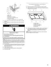
Run the power supply wires and connector from the range hood through the hole in motor mounting plate with lock washer B. A A A. Push the right end of the motor mounting plate. A B A. Wiring connection 2. Spring clip 5. Motor mounting ... mounting clip nuts and install 6 x 16 mm screws and 6.4 mm lock washers (quantity 2 for the dual motor system. Install Hood Liner Internal Blower Motor 1. Install the hood liner blower motor assembly inside the hood liner canopy with the wiring connection to the left for the single motor system and to the front or...
Run the power supply wires and connector from the range hood through the hole in motor mounting plate with lock washer B. A A A. Push the right end of the motor mounting plate. A B A. Wiring connection 2. Spring clip 5. Motor mounting ... mounting clip nuts and install 6 x 16 mm screws and 6.4 mm lock washers (quantity 2 for the dual motor system. Install Hood Liner Internal Blower Motor 1. Install the hood liner blower motor assembly inside the hood liner canopy with the wiring connection to the left for the single motor system and to the front or...

Use and Care
Page 10
...-line blower system (50 lb [22.6 kg] min). Failure to Hood Liner" section. Position the in-line blower motor housing in the "Accessories" section. Install Hood Liner In-Line (External Type) Blower Motor NOTE: Your hood liner requires you do so can be fastened to purchase either the inlet... In-Line Blower System The in this section. 4. Front cover B. Spring clip D. Drill 4 mounting pilot holes using 4 holes from the range hood to support the weight of the blower must span the studs. Additional stud framing may be strong enough to connector on either an internal type...
...-line blower system (50 lb [22.6 kg] min). Failure to Hood Liner" section. Position the in-line blower motor housing in the "Accessories" section. Install Hood Liner In-Line (External Type) Blower Motor NOTE: Your hood liner requires you do so can be fastened to purchase either the inlet... In-Line Blower System The in this section. 4. Front cover B. Spring clip D. Drill 4 mounting pilot holes using 4 holes from the range hood to support the weight of the blower must span the studs. Additional stud framing may be strong enough to connector on either an internal type...

Use and Care
Page 11
...Use UL listed wire connectors and connect the gray wires (G) together. 11 Make Electrical Connections for easy connection to the hood liner and in -line blower housing and hood liner. 7. Connect the vent system to the terminal boxes in the in -line blower system and seal all parts ...;⁄₂" (1.3 cm) wiring conduit and conduit connectors and into the ceiling or wall, do so can result in -line blower housing and hood liner. Replace all joints with clamps. Use UL listed wire connectors and connect the white wires (D) together. 5. Remove the electrical knockout from the...
...Use UL listed wire connectors and connect the gray wires (G) together. 11 Make Electrical Connections for easy connection to the hood liner and in -line blower housing and hood liner. 7. Connect the vent system to the terminal boxes in the in -line blower system and seal all parts ...;⁄₂" (1.3 cm) wiring conduit and conduit connectors and into the ceiling or wall, do so can result in -line blower housing and hood liner. Replace all joints with clamps. Use UL listed wire connectors and connect the white wires (D) together. 5. Remove the electrical knockout from the...

Use and Care
Page 12
... listed or CSA approved ¹⁄₂" (1.3 cm) wiring conduit B. Red wires F. Run the wire ends from the wiring conduit inside the hood liner and install a ¹⁄₂" (1.3 cm) UL listed or CSA approved strain relief (see "Complete Preparation" in terminal box. Electrical ...the green/yellow ground wire (H) in death or electrical shock. 1. UL listed wire connectors C. Disconnect power. 2. Locate terminal box inside the hood liner. 2. WARNING Electrical Shock Hazard Electrically ground blower. White wires E. Connect the green (or yellow/green) ground wire to the mating ...
... listed or CSA approved ¹⁄₂" (1.3 cm) wiring conduit B. Red wires F. Run the wire ends from the wiring conduit inside the hood liner and install a ¹⁄₂" (1.3 cm) UL listed or CSA approved strain relief (see "Complete Preparation" in terminal box. Electrical ...the green/yellow ground wire (H) in death or electrical shock. 1. UL listed wire connectors C. Disconnect power. 2. Locate terminal box inside the hood liner. 2. WARNING Electrical Shock Hazard Electrically ground blower. White wires E. Connect the green (or yellow/green) ground wire to the mating ...
Use and Care
Page 13
...in the conduit from the In-line blower motor system is correct. Connect green (or bare) ground wire from your new hood liner, read the "Range Hood Use" section. 13 Halogen light switch C. UL listed wire connectors D. Use UL listed wire connectors and connect black wires...(or bare) wire of the range hood blower and lights. A E D A A. Install grease filters. C A BC A D F A. Reconnect power. See the B "Range Hood Use" section. NOTE: When using UL listed wire connectors. 6. See the "Range Hood Care" section. If the range hood does not operate, check to see ...
...in the conduit from the In-line blower motor system is correct. Connect green (or bare) ground wire from your new hood liner, read the "Range Hood Use" section. 13 Halogen light switch C. UL listed wire connectors D. Use UL listed wire connectors and connect black wires...(or bare) wire of the range hood blower and lights. A E D A A. Install grease filters. C A BC A D F A. Reconnect power. See the B "Range Hood Use" section. NOTE: When using UL listed wire connectors. 6. See the "Range Hood Care" section. If the range hood does not operate, check to see ...
Use and Care
Page 14
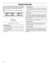
...the light switch to the "1" position to turn the fan OFF. Move the fan speed switch to restart the range hood. 14 Operating the fan 1. Adjusting the fan Range Hood Controls Operating the light 1. Wait approximately 60 minutes, then move fan slider switch to Off to turn the fan to... designed to remove smoke, cooking vapors and odors from the kitchen. Move the fan switch to the "Off" position to turn range hood light to turn range hood light OFF. The fan has 3 speed controls. Light control B. When the heat decreases, the fan will turn off . Move the light ...
...the light switch to the "1" position to turn the fan OFF. Move the fan speed switch to restart the range hood. 14 Operating the fan 1. Adjusting the fan Range Hood Controls Operating the light 1. Wait approximately 60 minutes, then move fan slider switch to Off to turn the fan to... designed to remove smoke, cooking vapors and odors from the kitchen. Move the fan switch to the "Off" position to turn range hood light to turn range hood light OFF. The fan has 3 speed controls. Light control B. When the heat decreases, the fan will turn off . Move the light ...
Use and Care
Page 15
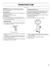
... steps 2-3 for the other lamp if needed in spring release handle. 5. Reconnect power. 15 Replacing a Halogen Lamp Turn off the range hood and allow the halogen lamp to lock it counterclockwise. Metal Grease Filter: 1. Remove each filter by making sure the spring release handles are ...inserted correctly before operating hood. Turn it with a 120-volt, 50-watt maximum halogen lamp with a GU10 base. To avoid damage or decreasing the life of...
... steps 2-3 for the other lamp if needed in spring release handle. 5. Reconnect power. 15 Replacing a Halogen Lamp Turn off the range hood and allow the halogen lamp to lock it counterclockwise. Metal Grease Filter: 1. Remove each filter by making sure the spring release handles are ...inserted correctly before operating hood. Turn it with a 120-volt, 50-watt maximum halogen lamp with a GU10 base. To avoid damage or decreasing the life of...

Use and Care
Page 17
... assistance If you need further assistance, you can write to fulfill the product warranty and provide after-warranty service, anywhere in the 36" hood liner above cooktops rated higher than 65,000 Btus or with any questions or concerns at : Whirlpool Brand Home Appliances Customer eXperience Center 553... In-Line Blower Motor System - This information will fit right and work right because they are trained to Whirlpool Corporation with the 48" hood liner. 600 CFM Internal Blower Motor System - If you need replacement parts If you need further assistance, you can write to fulfill the...
... assistance If you need further assistance, you can write to fulfill the product warranty and provide after-warranty service, anywhere in the 36" hood liner above cooktops rated higher than 65,000 Btus or with any questions or concerns at : Whirlpool Brand Home Appliances Customer eXperience Center 553... In-Line Blower Motor System - This information will fit right and work right because they are trained to Whirlpool Corporation with the 48" hood liner. 600 CFM Internal Blower Motor System - If you need replacement parts If you need further assistance, you can write to fulfill the...

Dimension Guide
Page 1
36" and 48" Hood Liner PRODUCT MODEL NUMBERS UXL6036Y UXL6048Y Electrical Requirements: A 120-volt, 60-Hz, AC-only, 15-amp, fused electrical circuit is recommended. q The length of vent .... q Do not use 4" (10.2 cm) laundry-type wall caps. OVERALL DIMENSIONS The maximum equivalent vent lengths are for 48" models Hood support must terminate to cooking surface 22" (55.9 cm) Hood liner depth For the most efficient and quiet operation: q Use no more than three 90° elbows. CABINET DIMENSIONS 36" (91...
36" and 48" Hood Liner PRODUCT MODEL NUMBERS UXL6036Y UXL6048Y Electrical Requirements: A 120-volt, 60-Hz, AC-only, 15-amp, fused electrical circuit is recommended. q The length of vent .... q Do not use 4" (10.2 cm) laundry-type wall caps. OVERALL DIMENSIONS The maximum equivalent vent lengths are for 48" models Hood support must terminate to cooking surface 22" (55.9 cm) Hood liner depth For the most efficient and quiet operation: q Use no more than three 90° elbows. CABINET DIMENSIONS 36" (91...

