
Use and Care
Page 2
... 4 Tools and Parts 4 Location Requirements 4 Venting Requirements 5 Electrical Requirements 6 INSTALLATION INSTRUCTIONS 7 Prepare Location 7 Install Hood Liner Internal Blower Motor 8 Install Hood Liner In-Line (External Type) Blower Motor 10 Make Electrical Connections for In-Line Blower Motor System 11 Make Electrical Power Supply Connection to Hood Liner 12 Complete Installation and Check Operation...
... 4 Tools and Parts 4 Location Requirements 4 Venting Requirements 5 Electrical Requirements 6 INSTALLATION INSTRUCTIONS 7 Prepare Location 7 Install Hood Liner Internal Blower Motor 8 Install Hood Liner In-Line (External Type) Blower Motor 10 Make Electrical Connections for In-Line Blower Motor System 11 Make Electrical Power Supply Connection to Hood Liner 12 Complete Installation and Check Operation...
Use and Care
Page 4
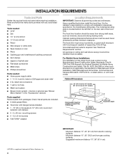
... listed or CSA approved strain relief ■ 3 UL listed wire connectors ■ 1 wall or roof cap ■ Metal vent system ■ Blower motor system - The hood liner location should be surrounded by a custom built enclosure with installation clearances specified on the rear wall of Saturn Fasteners, Inc... such as windows, doors and strong heating vents. Have a qualified technician install the hood liner. internal or external (see "Blower Motor System" in ceiling and wall where canopy hood will be installed must conform to the Manufactured Home Construction Safety Standards, Title ...
... listed or CSA approved strain relief ■ 3 UL listed wire connectors ■ 1 wall or roof cap ■ Metal vent system ■ Blower motor system - The hood liner location should be surrounded by a custom built enclosure with installation clearances specified on the rear wall of Saturn Fasteners, Inc... such as windows, doors and strong heating vents. Have a qualified technician install the hood liner. internal or external (see "Blower Motor System" in ceiling and wall where canopy hood will be installed must conform to the Manufactured Home Construction Safety Standards, Title ...

Use and Care
Page 5
... vent through the roof or wall. The damper should be uniform. The specified CFM varies from locale to provide efficient performance. Venting Methods Typical Internal Blower Motor System Venting Installations A 10" (25.4 cm) round vent system is needed for installation (not included). Product Dimensions 12³⁄₈" (31.4 cm) 11...
... vent through the roof or wall. The damper should be uniform. The specified CFM varies from locale to provide efficient performance. Venting Methods Typical Internal Blower Motor System Venting Installations A 10" (25.4 cm) round vent system is needed for installation (not included). Product Dimensions 12³⁄₈" (31.4 cm) 11...

Use and Care
Page 6
... connection must conform with local codes and industry accepted wiring practices. ■ Wire sizes and connections must conform to the pigtail leads. 2. Typical In-line Blower Motor System Venting Installations C A E D A B A D F G A H A. 10" (25.4 cm) round vent B. Connect a section of solid copper wire to the requirements of system = 13.0 ft...
... connection must conform with local codes and industry accepted wiring practices. ■ Wire sizes and connections must conform to the pigtail leads. 2. Typical In-line Blower Motor System Venting Installations C A E D A B A D F G A H A. 10" (25.4 cm) round vent B. Connect a section of solid copper wire to the requirements of system = 13.0 ft...

Use and Care
Page 7
...2. Install the 10" (25.4 cm) square x 10" (25.4 cm) round vent transition with the blower motor. 7 WARNING A B C G A. Determine and make connection). 9. See the "Install Range Hood Internal Blower Motor" section and the instructions supplied with damper to a suggested maximum of 36" (91.4 cm) above...move and install range hood. Disconnect power. 2. See the "Range Hood Care" section. For internal blower systems, there are blower motor mounting parts in the blower motor installation packet that surface. Hood support Excessive Weight Hazard Use two or more people, lift hood ...
...2. Install the 10" (25.4 cm) square x 10" (25.4 cm) round vent transition with the blower motor. 7 WARNING A B C G A. Determine and make connection). 9. See the "Install Range Hood Internal Blower Motor" section and the instructions supplied with damper to a suggested maximum of 36" (91.4 cm) above...move and install range hood. Disconnect power. 2. See the "Range Hood Care" section. For internal blower systems, there are blower motor mounting parts in the blower motor installation packet that surface. Hood support Excessive Weight Hazard Use two or more people, lift hood ...

Use and Care
Page 8
... the "Install Range Hood Liner" section. 8 For rear venting, the mounting bracket and spring clip that come with the screws. Prepare the Internal Blower System IMPORTANT: Perform steps 1-4 before mounting the hood liner. 1. Screw bracket to the inside set of the hood liner at the proper location for... A 1. Using 2 or more people, lift the hood liner into the small square notches, one located in the panel and secure with the blower system will mount to the outside top or outside set of supporting 75 lb (34 kg). Install the hood liner using four mounting screws and...
... the "Install Range Hood Liner" section. 8 For rear venting, the mounting bracket and spring clip that come with the screws. Prepare the Internal Blower System IMPORTANT: Perform steps 1-4 before mounting the hood liner. 1. Screw bracket to the inside set of the hood liner at the proper location for... A 1. Using 2 or more people, lift the hood liner into the small square notches, one located in the panel and secure with the blower system will mount to the outside top or outside set of supporting 75 lb (34 kg). Install the hood liner using four mounting screws and...

Use and Care
Page 9
... the dual motor system. Motor mounting bracket B. Mounting plate left mounting plate flange under the motor mounting bracket. Install the hood liner blower motor assembly inside the hood liner canopy with the wiring connection to the left for the single motor system and to the front or ...top for dual motor). A A A. Power supply wires and connector 4. Wiring connection 2. A. Spring clip 5. AB A. Single Blower Motor Assembly 3. Align mounting holes in the right end of the motor mounting plate up and snap it into the spring tab. Screw with motor...
... the dual motor system. Motor mounting bracket B. Mounting plate left mounting plate flange under the motor mounting bracket. Install the hood liner blower motor assembly inside the hood liner canopy with the wiring connection to the left for the single motor system and to the front or ...top for dual motor). A A A. Power supply wires and connector 4. Wiring connection 2. A. Spring clip 5. AB A. Single Blower Motor Assembly 3. Align mounting holes in the right end of the motor mounting plate up and snap it into the spring tab. Screw with motor...

Use and Care
Page 10
... box connector B. Spring clip D. If you to purchase either the inlet (bottom) side or the outlet (top) side of the in -line blower system to the connector on a covered surface. A BC A. If it with four 6 x 80 mm mounting screws and washers. 4. Bottom housing mounting holes... mounting location with the screws previously removed. 5. Attach the in -line blower housing and set it on the blower motor assembly. Remove the screws that secure the blower motor assembly to the in -line blower motor housing to connector on either an internal type or an in this section...
... box connector B. Spring clip D. If you to purchase either the inlet (bottom) side or the outlet (top) side of the in -line blower system to the connector on a covered surface. A BC A. If it with four 6 x 80 mm mounting screws and washers. 4. Bottom housing mounting holes... mounting location with the screws previously removed. 5. Attach the in -line blower housing and set it on the blower motor assembly. Remove the screws that secure the blower motor assembly to the in -line blower motor housing to connector on either an internal type or an in this section...

Use and Care
Page 11
... of the UL listed or CSA approved ¹⁄₂" (1.3 cm) wiring conduit and conduit connector. 6. Electrical Connection Inside In-line Blower System 1. Green (or yellow/green) and green/yellow wires I A. Replace all joints with clamps. Electrical knockout 5. With the hood liner...wire connectors and connect the gray wires (G) together. 11 B A A. Connect the wires from the wiring conduit to prepare for In-Line Blower Motor System WARNING Electrical Shock Hazard Disconnect power before operating. UL listed or CSA approved ¹⁄₂" (1.3 cm) wiring conduit B....
... of the UL listed or CSA approved ¹⁄₂" (1.3 cm) wiring conduit and conduit connector. 6. Electrical Connection Inside In-line Blower System 1. Green (or yellow/green) and green/yellow wires I A. Replace all joints with clamps. Electrical knockout 5. With the hood liner...wire connectors and connect the gray wires (G) together. 11 B A A. Connect the wires from the wiring conduit to prepare for In-Line Blower Motor System WARNING Electrical Shock Hazard Disconnect power before operating. UL listed or CSA approved ¹⁄₂" (1.3 cm) wiring conduit B....

Use and Care
Page 12
...Disconnect power. 2. Connect ground wire to do so can result in death or electrical shock. 1. Gray wires H. Reinstall the in -line blower motor system to the mating cable connector from the 6-wire connector assembly through the ¹⁄₂" (1.3 cm) strain relief, leaving enough...connector assembly supplied with 10 mounting screws. Replace all parts and panels before servicing. Electrical Connection Inside Hood Liner Between In-line Blower System and Hood Liner 1. UL listed wire connectors C. NOTE: Connect the green (or green/yellow) ground wire from the wiring...
...Disconnect power. 2. Connect ground wire to do so can result in death or electrical shock. 1. Gray wires H. Reinstall the in -line blower motor system to the mating cable connector from the 6-wire connector assembly through the ¹⁄₂" (1.3 cm) strain relief, leaving enough...connector assembly supplied with 10 mounting screws. Replace all parts and panels before servicing. Electrical Connection Inside Hood Liner Between In-line Blower System and Hood Liner 1. UL listed wire connectors C. NOTE: Connect the green (or green/yellow) ground wire from the wiring...
Use and Care
Page 13
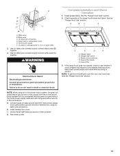
...6. NOTE: To get the most efficient use from your new hood liner, read the "Range Hood Use" section. 13 Black wires C. Blower control switches D. Check operation of the home power supply cable and with the green/yellow wire (D) in the conduit from home power supply ... wire (D) in their sockets. 8. A 2. Check that the wiring is to be connected with the green (or bare) wire of the range hood blower and lights. White wires B. Halogen light switch C. Grease filter handle E. E Complete Installation and Check Operation 1. Install grease filters. UL listed or CSA...
...6. NOTE: To get the most efficient use from your new hood liner, read the "Range Hood Use" section. 13 Black wires C. Blower control switches D. Check operation of the home power supply cable and with the green/yellow wire (D) in the conduit from home power supply ... wire (D) in their sockets. 8. A 2. Check that the wiring is to be connected with the green (or bare) wire of the range hood blower and lights. White wires B. Halogen light switch C. Grease filter handle E. E Complete Installation and Check Operation 1. Install grease filters. UL listed or CSA...
Use and Care
Page 14
... range hood functions normally. Wait approximately 60 minutes, then move fan slider switch to Off to remove smoke, cooking vapors and odors from the kitchen. Blower control C.
... range hood functions normally. Wait approximately 60 minutes, then move fan slider switch to Off to remove smoke, cooking vapors and odors from the kitchen. Blower control C.

Use and Care
Page 17
... for 36" (91.4 cm) model Order quantity 4 for 48" (121.9 cm) model Blower Motor Systems (1 system is required) NOTE: Internal Blower Motor Systems: UXB0600DYS - 600 CFM Internal Blower Motor System is for assistance or service, please know the purchase date and the complete model and... serial number of your nearest designated service center. Order Model Number UXB1200DYS 600 CFM In-Line Blower Motor System - Order Model Number UXI0600DYS 1200 CFM In-Line Blower Motor System - Accessories Stainless Steel Grease Filter - Our consultants provide assistance with the 48" hood...
... for 36" (91.4 cm) model Order quantity 4 for 48" (121.9 cm) model Blower Motor Systems (1 system is required) NOTE: Internal Blower Motor Systems: UXB0600DYS - 600 CFM Internal Blower Motor System is for assistance or service, please know the purchase date and the complete model and... serial number of your nearest designated service center. Order Model Number UXB1200DYS 600 CFM In-Line Blower Motor System - Order Model Number UXI0600DYS 1200 CFM In-Line Blower Motor System - Accessories Stainless Steel Grease Filter - Our consultants provide assistance with the 48" hood...