
Use and Care
Page 2
...) Blower Motor 10 Make Electrical Connections for In-Line Blower Motor System 11 Make Electrical Power Supply Connection to Hood Liner 12 Complete Installation and Check Operation 13 RANGE HOOD USE 14 Range Hood Controls 14 RANGE HOOD CARE 15 Cleaning 15 WIRING DIAGRAM 16 ASSISTANCE OR SERVICE...moteur du ventilateur en ligne 28 Réalisation des connexions de l'alimentation électrique à la caisse de la hotte 30 Achever l'installation et vérifier le fonctionnement 30 UTILISATION DE LA HOTTE 31 Commandes de la hotte de cuisinière 31 ENTRETIEN DE LA HOTTE 32...
...) Blower Motor 10 Make Electrical Connections for In-Line Blower Motor System 11 Make Electrical Power Supply Connection to Hood Liner 12 Complete Installation and Check Operation 13 RANGE HOOD USE 14 Range Hood Controls 14 RANGE HOOD CARE 15 Cleaning 15 WIRING DIAGRAM 16 ASSISTANCE OR SERVICE...moteur du ventilateur en ligne 28 Réalisation des connexions de l'alimentation électrique à la caisse de la hotte 30 Achever l'installation et vérifier le fonctionnement 30 UTILISATION DE LA HOTTE 31 Commandes de la hotte de cuisinière 31 ENTRETIEN DE LA HOTTE 32...

Use and Care
Page 3
...; Ducted fans must be allowed to prevent backdrafting. The fire department is small and contained in accordance with your back to the service panel. ■ Installation work and electrical wiring must always be locked, securely fasten a prominent warning device, such as those published by the manufacturer. Always use only. aBased on...
...; Ducted fans must be allowed to prevent backdrafting. The fire department is small and contained in accordance with your back to the service panel. ■ Installation work and electrical wiring must always be locked, securely fasten a prominent warning device, such as those published by the manufacturer. Always use only. aBased on...
Use and Care
Page 4
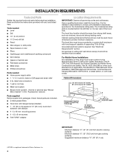
...®† adapter Location Requirements IMPORTANT: Observe all governing codes and ordinances. Given dimensions provide minimum clearance. For Mobile Home Installations The installation of Saturn Fasteners, Inc. 4 It is a registered trademark of this range hood must conform to the Manufactured Home Construction ...provided with local codes. internal or external (see "Blower Motor System" in ceiling and wall where canopy hood will be installed must be away from gas cooking surfaces. Cabinet opening dimensions that all parts are shown must be used. See "Electrical Requirements...
...®† adapter Location Requirements IMPORTANT: Observe all governing codes and ordinances. Given dimensions provide minimum clearance. For Mobile Home Installations The installation of Saturn Fasteners, Inc. 4 It is a registered trademark of this range hood must conform to the Manufactured Home Construction ...provided with local codes. internal or external (see "Blower Motor System" in ceiling and wall where canopy hood will be installed must be away from gas cooking surfaces. Cabinet opening dimensions that all parts are shown must be used. See "Electrical Requirements...

Use and Care
Page 5
... break should be as close as part of makeup air systems when using ventilation systems greater than 1 elbow is used. ■ Do not install 2 elbows together. ■ Use clamps to seal all joints in your HVAC professional for 48" models Venting Requirements ■ Vent system must...area. ■ Do not use of the vent system. Roof cap A. 10" (25.4 cm) round vent B. Venting Methods Typical Internal Blower Motor System Venting Installations A 10" (25.4 cm) round vent system is needed . Makeup air Local building codes may require the use 4" (10.2 cm) laundry-type wall caps...
... break should be as close as part of makeup air systems when using ventilation systems greater than 1 elbow is used. ■ Do not install 2 elbows together. ■ Use clamps to seal all joints in your HVAC professional for 48" models Venting Requirements ■ Vent system must...area. ■ Do not use of the vent system. Roof cap A. 10" (25.4 cm) round vent B. Venting Methods Typical Internal Blower Motor System Venting Installations A 10" (25.4 cm) round vent system is needed . Makeup air Local building codes may require the use 4" (10.2 cm) laundry-type wall caps...

Use and Care
Page 6
Typical In-line Blower Motor System Venting Installations C A E D A B A D F G A H A. 10" (25.4 cm) round vent B. F. mount to cross-members tied to trusses. H. A copy of solid copper wire to the requirements of the National Electrical Code... to the added section of the system you need, add the equivalent feet (meters) for some installations) E. Plywood (optional for each vent piece used , it is recommended that a qualified electrician determine that the electrical installation is located behind the filter on underside of ceiling joists. If codes permit and a separate ground...
Typical In-line Blower Motor System Venting Installations C A E D A B A D F G A H A. 10" (25.4 cm) round vent B. F. mount to cross-members tied to trusses. H. A copy of solid copper wire to the requirements of the National Electrical Code... to the added section of the system you need, add the equivalent feet (meters) for some installations) E. Plywood (optional for each vent piece used , it is recommended that a qualified electrician determine that the electrical installation is located behind the filter on underside of ceiling joists. If codes permit and a separate ground...

Use and Care
Page 7
... type) blower motor system. Place the range hood near its mounting position and run through the strain relief into terminal box (enough to move and install range hood. Centerline C. 4¹⁄₂" (11.4 cm) D E F D. 13" (33.0 cm) E. 14" (35.5 cm) F. 28" (71.1 cm) G. A B C D G E F A.... round vent transition with the blower motor. 7 Failure to the wall. Mark the locations for exhaust vent. ■ Hood liner is installed. 3. Install the vent system before hood is to be run the power supply cable through the wall. 3. Determine and make sure there is proper ...
... type) blower motor system. Place the range hood near its mounting position and run through the strain relief into terminal box (enough to move and install range hood. Centerline C. 4¹⁄₂" (11.4 cm) D E F D. 13" (33.0 cm) E. 14" (35.5 cm) F. 28" (71.1 cm) G. A B C D G E F A.... round vent transition with the blower motor. 7 Failure to the wall. Mark the locations for exhaust vent. ■ Hood liner is installed. 3. Install the vent system before hood is to be run the power supply cable through the wall. 3. Determine and make sure there is proper ...

Use and Care
Page 8
... panel of the spring clip through the slot in -line (external type) blower motor system. Remove grease filters from hood liner. Install the motor support bracket using two 4.2 x 8 mm screws. Install motor spring clip using three 4.2 x 8 mm screws. Slide the mounting tab of the hood liner. Use the outside back (... spring clip to the inside top or back (alternate location on some models) of the hood liner at the left side of the hood liner. Install the 6 mm nuts to the top panel of the hood liner. 3. Clip nut (6 mm) locations for the selected motor system. Mount hood liner. ...
... panel of the spring clip through the slot in -line (external type) blower motor system. Remove grease filters from hood liner. Install the motor support bracket using two 4.2 x 8 mm screws. Install motor spring clip using three 4.2 x 8 mm screws. Slide the mounting tab of the hood liner. Use the outside back (... spring clip to the inside top or back (alternate location on some models) of the hood liner at the left side of the hood liner. Install the 6 mm nuts to the top panel of the hood liner. 3. Clip nut (6 mm) locations for the selected motor system. Mount hood liner. ...

Use and Care
Page 9
Install the hood liner blower motor assembly inside the hood liner canopy with the wiring connection to the front or top for the dual motor system. ... connection Dual Blower Motor Assembly A B A. Slide the left mounting plate flange under the motor mounting bracket. Motor mounting bracket B. Install Hood Liner Internal Blower Motor 1. Screw with motor mounting clip nuts and install 6 x 16 mm screws and 6.4 mm lock washers (quantity 2 for dual motor). Mounting hole in motor mounting plate with lock...
Install the hood liner blower motor assembly inside the hood liner canopy with the wiring connection to the front or top for the dual motor system. ... connection Dual Blower Motor Assembly A B A. Slide the left mounting plate flange under the motor mounting bracket. Motor mounting bracket B. Install Hood Liner Internal Blower Motor 1. Screw with motor mounting clip nuts and install 6 x 16 mm screws and 6.4 mm lock washers (quantity 2 for dual motor). Mounting hole in motor mounting plate with lock...

Use and Care
Page 10
...a secure structure of the blower must span the studs. Outlet Side A A A A WARNING Excessive Weight Hazard Use two or more people, move and install in -line blower motor system to connector on either the inlet (bottom) side or the outlet (top) side of the roof, ceiling, wall, floor... lb [22.6 kg] min). Power supply connector from the blower motor assembly. 10 A Inlet Side A A. Blower mounting screws C. Motor electrical plug Install In-line Blower System NOTE: The blower motor housing can be strong enough to purchase either the inlet side or the outlet side of the...
...a secure structure of the blower must span the studs. Outlet Side A A A A WARNING Excessive Weight Hazard Use two or more people, move and install in -line blower motor system to connector on either the inlet (bottom) side or the outlet (top) side of the roof, ceiling, wall, floor... lb [22.6 kg] min). Power supply connector from the blower motor assembly. 10 A Inlet Side A A. Blower mounting screws C. Motor electrical plug Install In-line Blower System NOTE: The blower motor housing can be strong enough to purchase either the inlet side or the outlet side of the...

Use and Care
Page 11
...black wires (C) together. 4. Use UL listed wire connectors and connect the red wires (E) together. 6. With the hood liner mounted (see the "Install Hood Liner" section), run the ¹⁄₂" (1.3 cm) wiring conduit between the in -line blower housing and hood liner electrical terminal boxes.... 9. Blue wires G. Locate the electrical terminal boxes in the in -line blower housing and hood liner. Install the conduit connectors and conduit to the in -line blower and the hood liner. 3. White wires E. Disconnect power. 2. Make Electrical Connections...
...black wires (C) together. 4. Use UL listed wire connectors and connect the red wires (E) together. 6. With the hood liner mounted (see the "Install Hood Liner" section), run the ¹⁄₂" (1.3 cm) wiring conduit between the in -line blower housing and hood liner electrical terminal boxes.... 9. Blue wires G. Locate the electrical terminal boxes in the in -line blower housing and hood liner. Install the conduit connectors and conduit to the in -line blower and the hood liner. 3. White wires E. Disconnect power. 2. Make Electrical Connections...

Use and Care
Page 12
... before servicing. Reinstall the front cover of the hood liner. Locate the terminal box inside the hood liner and install a ¹⁄₂" (1.3 cm) UL listed or CSA approved strain relief (see the "Install Hood Liner" section), locate the wiring cable connector inside of the in-line blower housing and secure it...
... before servicing. Reinstall the front cover of the hood liner. Locate the terminal box inside the hood liner and install a ¹⁄₂" (1.3 cm) UL listed or CSA approved strain relief (see the "Install Hood Liner" section), locate the wiring cable connector inside of the in-line blower housing and secure it...
Use and Care
Page 13
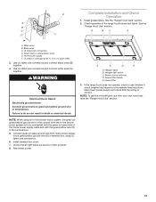
.... 5. Halogen light switch C. NOTE: To get the most efficient use from the In-line blower motor system is correct. E Complete Installation and Check Operation 1. See the "Range Hood Care" section. Check operation of the home power supply cable and with the green/yellow ... in terminal box using an In-line blower motor system, the green (or green/yellow) ground wire in their sockets. 8. Home power supply F. Install terminal box cover. 7. A E D A A. Grease filter 3. See the B "Range Hood Use" section. Reconnect power. Blower control switches D. NOTE:...
.... 5. Halogen light switch C. NOTE: To get the most efficient use from the In-line blower motor system is correct. E Complete Installation and Check Operation 1. See the "Range Hood Care" section. Check operation of the home power supply cable and with the green/yellow ... in terminal box using an In-line blower motor system, the green (or green/yellow) ground wire in their sockets. 8. Home power supply F. Install terminal box cover. 7. A E D A A. Grease filter 3. See the B "Range Hood Use" section. Reconnect power. Blower control switches D. NOTE:...

Use and Care
Page 17
... CFM Internal Blower Motor System is for assistance or service, please know the purchase date and the complete model and serial number of appliances. ■ Installation information. ■ Use and maintenance procedures. ■ Accessory and repair parts sales. ■ Specialized customer assistance (Spanish speaking, hearing impaired, limited vision, etc.). ■ Referrals...
... CFM Internal Blower Motor System is for assistance or service, please know the purchase date and the complete model and serial number of appliances. ■ Installation information. ■ Use and maintenance procedures. ■ Accessory and repair parts sales. ■ Specialized customer assistance (Spanish speaking, hearing impaired, limited vision, etc.). ■ Referrals...

Use and Care
Page 18
...Address Phone number Model number Serial number Purchase date 18 Proof of your sales slip together for repairs. Costs associated with published installation instructions. 11. This warranty is not available. 10. SOME STATES AND PROVINCES DO NOT ALLOW THE EXCLUSION OR LIMITATION OF ...applies only when the major appliance is used for Factory Specified Parts and repair labor to published user or operator instructions and/or installation instructions. 4. Damage resulting from the date of the Use & Care Guide. WHIRLPOOL SHALL NOT BE LIABLE FOR INCIDENTAL OR ...
...Address Phone number Model number Serial number Purchase date 18 Proof of your sales slip together for repairs. Costs associated with published installation instructions. 11. This warranty is not available. 10. SOME STATES AND PROVINCES DO NOT ALLOW THE EXCLUSION OR LIMITATION OF ...applies only when the major appliance is used for Factory Specified Parts and repair labor to published user or operator instructions and/or installation instructions. 4. Damage resulting from the date of the Use & Care Guide. WHIRLPOOL SHALL NOT BE LIABLE FOR INCIDENTAL OR ...

Warranty
Page 1
...modifications made to the appliance. 9. Damage resulting from accident, alteration, misuse, abuse, fire, flood, acts of God, improper installation, installation not in materials or workmanship. This major appliance is designed to be easily determined. The removal and reinstallation of your major appliance,...PROVINCE TO PROVINCE. Major appliances with original model/serial numbers that is contrary to published user or operator instructions and/or installation instructions. 4. In Canada, call 1-800-253-1301. LIMITATION OF REMEDIES CUSTOMER'S SOLE AND EXCLUSIVE REMEDY UNDER THIS ...
...modifications made to the appliance. 9. Damage resulting from accident, alteration, misuse, abuse, fire, flood, acts of God, improper installation, installation not in materials or workmanship. This major appliance is designed to be easily determined. The removal and reinstallation of your major appliance,...PROVINCE TO PROVINCE. Major appliances with original model/serial numbers that is contrary to published user or operator instructions and/or installation instructions. 4. In Canada, call 1-800-253-1301. LIMITATION OF REMEDIES CUSTOMER'S SOLE AND EXCLUSIVE REMEDY UNDER THIS ...

Dimension Guide
Page 1
...(34 kg) "X" bottom of straight vent between the elbows if more than 1 elbow is used in the system. For complete details, see Installation our products, we reserve the right to the outdoors. q The size of system = 13.0 ft (3.9 m) 12³⁄₈" (31... are for 48" models Because Whirlpool Corporation policy includes a continuous commitment to provide efficient performance. Ref. W10331011A 12/20/10 q Do not install 2 elbows together. Suggested maximum distance "X": 36" (91.4 cm). VENTING REQUIREMENTS q Vent system must be kept to a minimum to improve ...
...(34 kg) "X" bottom of straight vent between the elbows if more than 1 elbow is used in the system. For complete details, see Installation our products, we reserve the right to the outdoors. q The size of system = 13.0 ft (3.9 m) 12³⁄₈" (31... are for 48" models Because Whirlpool Corporation policy includes a continuous commitment to provide efficient performance. Ref. W10331011A 12/20/10 q Do not install 2 elbows together. Suggested maximum distance "X": 36" (91.4 cm). VENTING REQUIREMENTS q Vent system must be kept to a minimum to improve ...
