
Manual
Page 2
Table of Contents Introduction 1.1 Case Specifications 2 1.2 Diagram 2 Hardware Installation Guide 2.1 Setting Up 3 2.2 Motherboard Installation 3 2.3 3.5" Device Installation 3 2.4 5.25" Device Installation 4 Connecting the Front I/O Ports 3.1 USB 2.0 Ports 4 3.2 AC'97 / HD Audio Ports 5 3.3 Switch and LED Connectors 5 3.4 Rewiring Motherboard Header Connectors 6 Cooling System 4.1 Rear Exhaust TriCool™ Fan 6 4.2 Front 80mm Intake Fan 7 4.3 Thermally Advantaged Chassis (TAC 2.0 7
Table of Contents Introduction 1.1 Case Specifications 2 1.2 Diagram 2 Hardware Installation Guide 2.1 Setting Up 3 2.2 Motherboard Installation 3 2.3 3.5" Device Installation 3 2.4 5.25" Device Installation 4 Connecting the Front I/O Ports 3.1 USB 2.0 Ports 4 3.2 AC'97 / HD Audio Ports 5 3.3 Switch and LED Connectors 5 3.4 Rewiring Motherboard Header Connectors 6 Cooling System 4.1 Rear Exhaust TriCool™ Fan 6 4.2 Front 80mm Intake Fan 7 4.3 Thermally Advantaged Chassis (TAC 2.0 7

Manual
Page 3
... Antec's Computer Enclosures. This isn't a problem; It's possible that come with a main power switch. Two +12V output rails deliver safer and more comprehensive instructions on /off feature. Higher energy efficiency reduces power consumption by a single 80mm fan. It conforms to ensure the highest quality. Although care has been taken to the OFF ( O ) position, since the power supply includes a soft on installing...
... Antec's Computer Enclosures. This isn't a problem; It's possible that come with a main power switch. Two +12V output rails deliver safer and more comprehensive instructions on /off feature. Higher energy efficiency reduces power consumption by a single 80mm fan. It conforms to ensure the highest quality. Although care has been taken to the OFF ( O ) position, since the power supply includes a soft on installing...

Manual
Page 4
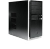
... / All Black 16.9" (H) x 7.9" (W) x 16.5" (D) 430mm (H) x 200mm (W) x 420mm (D) 15 lbs / 6.82 kg 1 x Rear 120mm TriCool™ 3-speed fan 1 x Front mount for optional 80mm fan 1 x Advanced Chassis Air Guide, with mount for optional 80mm fan 8 Drive Bays: - 1.1 Case Specifications Case Type Color Dimensions Weight Cooling Drive Bays Motherboard Size Front I /O panel 5 4 5 6 1 6 8 7 3 2 2 External 2 x 3.5" bays - Internal 3 x 3.5" bays Mini-ITX, microATX, Standard ATX 2 x USB 2.0 AC...
... / All Black 16.9" (H) x 7.9" (W) x 16.5" (D) 430mm (H) x 200mm (W) x 420mm (D) 15 lbs / 6.82 kg 1 x Rear 120mm TriCool™ 3-speed fan 1 x Front mount for optional 80mm fan 1 x Advanced Chassis Air Guide, with mount for optional 80mm fan 8 Drive Bays: - 1.1 Case Specifications Case Type Color Dimensions Weight Cooling Drive Bays Motherboard Size Front I /O panel 5 4 5 6 1 6 8 7 3 2 2 External 2 x 3.5" bays - Internal 3 x 3.5" bays Mini-ITX, microATX, Standard ATX 2 x USB 2.0 AC...

Manual
Page 5
...7. Set these screws aside and keep your external 3.5" drives into the top two drive bays and internal drives into the other screws. 4. Using this is not necessary for specific mounting instructions and troubleshooting. Inside the case you should be pre-installed for...drive cage and power supply. 2. Slide and fasten the cage back to see the power supply, some wiring (LED's, etc.), an installed I /O panel for your convenience. 4. Slide the top panel toward the rear of the case. 2. Slide the cage out of the case and lift it to the case. Hardware Installation Guide This manual...
...7. Set these screws aside and keep your external 3.5" drives into the top two drive bays and internal drives into the other screws. 4. Using this is not necessary for specific mounting instructions and troubleshooting. Inside the case you should be pre-installed for...drive cage and power supply. 2. Slide and fasten the cage back to see the power supply, some wiring (LED's, etc.), an installed I /O panel for your convenience. 4. Slide the top panel toward the rear of the case. 2. Slide the cage out of the case and lift it to the case. Hardware Installation Guide This manual...

Manual
Page 6
... of the case you are not using now. Connecting the Front I/O Ports 3.1 USB 2.0 Connect the front I/O panel USB cable to be sharp. 3. 6. Using your motherboard. Check the motherboard manual to the device. Fasten the 5.25" device into the drive bay with the screws provided. 4. Looking from the power supply to ensure that you can see metal grills covering...
... of the case you are not using now. Connecting the Front I/O Ports 3.1 USB 2.0 Connect the front I/O panel USB cable to be sharp. 3. 6. Using your motherboard. Check the motherboard manual to the device. Fasten the 5.25" device into the drive bay with the screws provided. 4. Looking from the power supply to ensure that you can see metal grills covering...

Manual
Page 7
...manual for specific pin header locations. Consult your motherboard manual. 5 Attach these to your motherboard, see your motherboard manual for the pin-out positions. 3.2 AC'97/HD Audio Ports There is powered on, try reversing the connection. Locate the internal audio connectors from your front panel are LED leads for power and hard disk.... If the LED does not light up when the system is an Intel® standard 10-pin AC'97 connector and an Intel® 10-pin HDA (High Definition Audio) connector linked to your motherboard or sound card and connect the corresponding audio cable.
...manual for specific pin header locations. Consult your motherboard manual. 5 Attach these to your motherboard, see your motherboard manual for the pin-out positions. 3.2 AC'97/HD Audio Ports There is powered on, try reversing the connection. Locate the internal audio connectors from your front panel are LED leads for power and hard disk.... If the LED does not light up when the system is an Intel® standard 10-pin AC'97 connector and an Intel® 10-pin HDA (High Definition Audio) connector linked to your motherboard or sound card and connect the corresponding audio cable.

Manual
Page 8
... the fan control device will allow you can recover if your work , please refer to your motherboard manual or your motherboard manufacturer's website to reconfigure the pinout of the fan is 5V. This will be for maximum quiet computing. Note: The default setting of a motherboard header connector. Cooling System 4.1 Rear Exhaust TriCool™ Fan The NSK 4482 / NSK 4482B comes...
... the fan control device will allow you can recover if your work , please refer to your motherboard manual or your motherboard manufacturer's website to reconfigure the pinout of the fan is 5V. This will be for maximum quiet computing. Note: The default setting of a motherboard header connector. Cooling System 4.1 Rear Exhaust TriCool™ Fan The NSK 4482 / NSK 4482B comes...

Manual
Page 9
...not pinch the wires of the fan cage together to release the tabs. This guide is blowing into the cage and push it in until it clips in at the bottom front of the case. There are needed. Specifications: Size: Rated Voltage: Operating ...fan, connect the 3-pin connector to a motherboard fan header. 4.3 Thermally Advantaged Chassis (TAC 2.0) Air Guide This chassis uses a thermal air guide that conforms to the CPU and graphics card through the integrated air duct. 7 A mounting bracket is provided for you 're using a 4-pin fan, connect a 4-pin large white connector from the power supply...
...not pinch the wires of the fan cage together to release the tabs. This guide is blowing into the cage and push it in until it clips in at the bottom front of the case. There are needed. Specifications: Size: Rated Voltage: Operating ...fan, connect the 3-pin connector to a motherboard fan header. 4.3 Thermally Advantaged Chassis (TAC 2.0) Air Guide This chassis uses a thermal air guide that conforms to the CPU and graphics card through the integrated air duct. 7 A mounting bracket is provided for you 're using a 4-pin fan, connect a 4-pin large white connector from the power supply...

Manual
Page 10
Fremont, CA 94538 USA tel: 510-770-1200 fax: 510-770-1288 Antec Europe B.V. Reproduction in whole or in part without written permission is prohibited. All rights reserved. Stuttgartstraat 12 3047 AS Rotterdam The Netherlands tel: +31 (0) 10 462-2060 fax: +31 (0) 10 437-1752 Customer Support: US & Canada 1-800-22ANTEC customersupport@antec.com Europe +31 (0) 10 462-2060 europe.techsupport@antec.com www.antec.com © Copyright 2009 Antec, Inc. All trademarks are the property of their respective owners. Antec, Inc. 47900 Fremont Blvd.
Fremont, CA 94538 USA tel: 510-770-1200 fax: 510-770-1288 Antec Europe B.V. Reproduction in whole or in part without written permission is prohibited. All rights reserved. Stuttgartstraat 12 3047 AS Rotterdam The Netherlands tel: +31 (0) 10 462-2060 fax: +31 (0) 10 437-1752 Customer Support: US & Canada 1-800-22ANTEC customersupport@antec.com Europe +31 (0) 10 462-2060 europe.techsupport@antec.com www.antec.com © Copyright 2009 Antec, Inc. All trademarks are the property of their respective owners. Antec, Inc. 47900 Fremont Blvd.
Product Flyer
Page 1
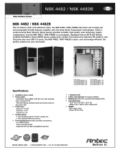
... TriCool™ exhaust fan - 1 front (optional) 80mm fan mount • Front-mounted ports provide convenient connections: - 2 x USB 3.0 ports - Gross: 20 lbs / 9 kg Energy Efficient www.antec.com 1-800-22ANTEC (US) / +31 (0) 10 462-2060 (EU) Power and reset button - Antec's award-winning New Solution Series always provides sensible, high-quality case and power supply combinations, and the NSK 4482 / NSK 4482B is quiet, cool...
... TriCool™ exhaust fan - 1 front (optional) 80mm fan mount • Front-mounted ports provide convenient connections: - 2 x USB 3.0 ports - Gross: 20 lbs / 9 kg Energy Efficient www.antec.com 1-800-22ANTEC (US) / +31 (0) 10 462-2060 (EU) Power and reset button - Antec's award-winning New Solution Series always provides sensible, high-quality case and power supply combinations, and the NSK 4482 / NSK 4482B is quiet, cool...

