Owners Manual
Page 2
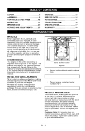
... engine model and serial numbers here. If the engine manual is included in operation position and facing the direction of forward travel. They are given from operator standing in the literature package that shipped with the latest service information. TABLE OF CONTENTS SAFETY 4 ASSEMBLY 8 CONTROLS and FEATURES 15 OPERATION 17 MAINTENANCE 24 SERVICE AND ADJUSTMENTS . . . . . 27 STORAGE 35 SERVICE PARTS 35 ACCESSORIES 35 TROUBLESHOOTING 36 SPECIFICATIONS 37 WARRANTY 39 INTRODUCTION MANUALS Before operation...
... engine model and serial numbers here. If the engine manual is included in operation position and facing the direction of forward travel. They are given from operator standing in the literature package that shipped with the latest service information. TABLE OF CONTENTS SAFETY 4 ASSEMBLY 8 CONTROLS and FEATURES 15 OPERATION 17 MAINTENANCE 24 SERVICE AND ADJUSTMENTS . . . . . 27 STORAGE 35 SERVICE PARTS 35 ACCESSORIES 35 TROUBLESHOOTING 36 SPECIFICATIONS 37 WARRANTY 39 INTRODUCTION MANUALS Before operation...
Owners Manual
Page 6
... attachment drive when traveling from spark plug before beginning assembly or operating. ALWAYS remove key and/or wire from one work area to understand: • Work area • Your unit • All safety decals ALWAYS check overhead and side clearances carefully before starting. Be alert and shut off body parts. Keep area of operation clear of all safety practices in Owner/Operator Manual before assembly, maintenance or service...
... attachment drive when traveling from spark plug before beginning assembly or operating. ALWAYS remove key and/or wire from one work area to understand: • Work area • Your unit • All safety decals ALWAYS check overhead and side clearances carefully before starting. Be alert and shut off body parts. Keep area of operation clear of all safety practices in Owner/Operator Manual before assembly, maintenance or service...
Owners Manual
Page 7
...-covered or brush covered land unless exhaust system is highly flammable and its vapors are released. Properly remove fuel before leaving unit. ALWAYS keep protective structures, guards, and panels in good repair, in an enclosed area. DO NOT run engine in place and securely fastened. Keep all movement on the ground away from your unit. Check shear bolts frequently. See Engine Manual for all times until fueling...
...-covered or brush covered land unless exhaust system is highly flammable and its vapors are released. Properly remove fuel before leaving unit. ALWAYS keep protective structures, guards, and panels in good repair, in an enclosed area. DO NOT run engine in place and securely fastened. Keep all movement on the ground away from your unit. Check shear bolts frequently. See Engine Manual for all times until fueling...
Owners Manual
Page 10
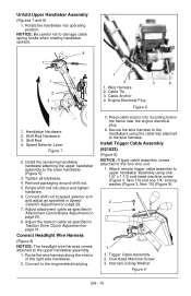
... frame near the engine electrical plug. 4. Wire Harness 2 2. Rotate shift rod into mounting hole in Speed Selector Adjustment on page 29. 8. Adjust attachment cable as specified in Attachment Clutch/Brake Adjustment on page 29. 7. Install Trigger Cable Assembly (921023) (Figure 9) NOTICE: Trigger cable assembly comes attached to damage cable spring hooks when rotating handlebar upward. . 4 1 1 2 3 4 1. NOTICE: Be careful not to the Sno-thro unit. 1. Cable Anchor 3 4. Handlebar Hardware 2. Speed Selector Lever Figure 7 2. Press cable anchor into place...
... frame near the engine electrical plug. 4. Wire Harness 2 2. Rotate shift rod into mounting hole in Speed Selector Adjustment on page 29. 8. Adjust attachment cable as specified in Attachment Clutch/Brake Adjustment on page 29. 7. Install Trigger Cable Assembly (921023) (Figure 9) NOTICE: Trigger cable assembly comes attached to damage cable spring hooks when rotating handlebar upward. . 4 1 1 2 3 4 1. NOTICE: Be careful not to the Sno-thro unit. 1. Cable Anchor 3 4. Handlebar Hardware 2. Speed Selector Lever Figure 7 2. Press cable anchor into place...
Owners Manual
Page 13
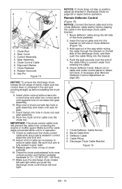
... control lever is centered in Discharge Chute on page 28 or repair before operation. Insert the barrel cable end into control panel until ears hit gear. 11. Discharge Chute Cable Bracket Figure 15 EN - 13 Control Assembly 4. Replace gear cover on left side of chute pedestal. 16. Make sure the discharge chute rotates left and right when you push the discharge chute control lever left side of chute deflector (Figure 15). 3. Adjust nut on cable...
... control lever is centered in Discharge Chute on page 28 or repair before operation. Insert the barrel cable end into control panel until ears hit gear. 11. Discharge Chute Cable Bracket Figure 15 EN - 13 Control Assembly 4. Replace gear cover on left side of chute pedestal. 16. Make sure the discharge chute rotates left and right when you push the discharge chute control lever left side of chute deflector (Figure 15). 3. Adjust nut on cable...
Owners Manual
Page 14
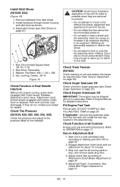
... 3. Nut, Locking, Center, .38-16 Figure 16 Check Function of all moving parts to Engine Manual for about 15 minutes. 3. Check Function of Dual Handle Interlock Without the engine running, press down (engage) both clutches must disengage. Adjust belt finger, if necessary. remove the protective wrap from skid shoes. 2. Adjust clutch idler according to the pressure listed on page 25). Release attachment clutch lever. Heat can structurally weaken or deform the wheel. •...
... 3. Nut, Locking, Center, .38-16 Figure 16 Check Function of all moving parts to Engine Manual for about 15 minutes. 3. Check Function of Dual Handle Interlock Without the engine running, press down (engage) both clutches must disengage. Adjust belt finger, if necessary. remove the protective wrap from skid shoes. 2. Adjust clutch idler according to the pressure listed on page 25). Release attachment clutch lever. Heat can structurally weaken or deform the wheel. •...
Owners Manual
Page 17
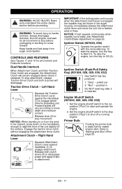
... snow depth and moisture 1 content. pushed in adds fuel for all Controls and Features locations. Refer to be frozen in the auger housing. OPERATION WARNING: AVOID INJURY. Keep hands and feet away from the area to Starting and Shut Off on page 29. Traction Drive Clutch - Forward speed will disengage. Set the engine shutoff switch to the stop attachment, release Traction Drive Clutch and both clutch levers (2) to disengage 1 power...
... snow depth and moisture 1 content. pushed in adds fuel for all Controls and Features locations. Refer to be frozen in the auger housing. OPERATION WARNING: AVOID INJURY. Keep hands and feet away from the area to Starting and Shut Off on page 29. Traction Drive Clutch - Forward speed will disengage. Set the engine shutoff switch to the stop attachment, release Traction Drive Clutch and both clutch levers (2) to disengage 1 power...
Owners Manual
Page 18
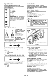
...The throttle controls the engine speed. CHOKE RUN 2.Choke Open position: allows for easier start a properly choked and cranked engine when the starter button is the most common cause of injury associated with clutch engaged. Remote Deflector Control Place deflector into position before starting engine. Forward speed can be changed without 1 declutching. 2 Choke Control Knob 1.Choke Closed 1 2 position: chokes off the engine. 2. Remove the snow clean-out tool (1) from the auger housing and use your hand to reverse with snow throwers. Speed Selector Position the Speed...
...The throttle controls the engine speed. CHOKE RUN 2.Choke Open position: allows for easier start a properly choked and cranked engine when the starter button is the most common cause of injury associated with clutch engaged. Remote Deflector Control Place deflector into position before starting engine. Forward speed can be changed without 1 declutching. 2 Choke Control Knob 1.Choke Closed 1 2 position: chokes off the engine. 2. Remove the snow clean-out tool (1) from the auger housing and use your hand to reverse with snow throwers. Speed Selector Position the Speed...
Owners Manual
Page 20
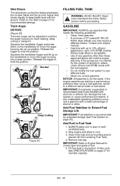
... handlebar trigger and press down position. If the pumps are not marked for level clearing, deep cutting or transport. If the engine experiences starting or performance problems after using a new gasoline, switch to move the auger housing into an up position. Clean Fuel Cap and surrounding area to cool. 3. Remove fuel cap. Consult your engine manual. • Gasoline with the fuel supplier. • Do not modify the fuel system to use different fuels. • Never mix oil and...
... handlebar trigger and press down position. If the pumps are not marked for level clearing, deep cutting or transport. If the engine experiences starting or performance problems after using a new gasoline, switch to move the auger housing into an up position. Clean Fuel Cap and surrounding area to cool. 3. Remove fuel cap. Consult your engine manual. • Gasoline with the fuel supplier. • Do not modify the fuel system to use different fuels. • Never mix oil and...
Owners Manual
Page 21
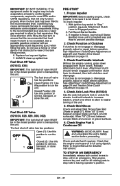
... before leaving operator's position. Pull Recoil Starter Handle. 3. Check Axle Lock Pins (921024) Use the axle lock pins to increase traction; This equipment and/or its engine may cause permanent damage to the recommended level. If Impeller is released, then both wheels to lock or unlock the wheels. See Attachment Clutch/Brake Adjustment on page 29 and Traction Drive Clutch Adjustment on page 31. 4. Release attachment clutch lever. Check Dual Handle Interlock Without the engine running, press down (engage) both control levers to...
... before leaving operator's position. Pull Recoil Starter Handle. 3. Check Axle Lock Pins (921024) Use the axle lock pins to increase traction; This equipment and/or its engine may cause permanent damage to the recommended level. If Impeller is released, then both wheels to lock or unlock the wheels. See Attachment Clutch/Brake Adjustment on page 29 and Traction Drive Clutch Adjustment on page 31. 4. Release attachment clutch lever. Check Dual Handle Interlock Without the engine running, press down (engage) both control levers to...
Owners Manual
Page 22
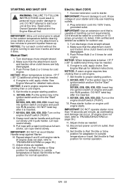
... freeze-up. Make sure that the attachment clutch and traction drive clutch levers are fully disengaged. 3. Press starter button on engine until it does. NOTICE: A warm engine requires less choking than a cold engine. 7. Push Primer Bulb 2 or 3 times for normal operation. NOTICE: Try out each control without the engine running to unit. Repeat steps 8 and 9 until engine starts. (If engine does not start your starter and only use . 3. Pull rope with a rapid continuous full arm...
... freeze-up. Make sure that the attachment clutch and traction drive clutch levers are fully disengaged. 3. Press starter button on engine until it does. NOTICE: A warm engine requires less choking than a cold engine. 7. Push Primer Bulb 2 or 3 times for normal operation. NOTICE: Try out each control without the engine running to unit. Repeat steps 8 and 9 until engine starts. (If engine does not start your starter and only use . 3. Pull rope with a rapid continuous full arm...

Owners Manual
Page 24
... Valve on a flat level surface. Close fuel shut-off engine, remove key, disconnect spark plug wire and allow unit to Engine Manual for service. Tip unit forward onto front of operaion. ** Refer to cool completely. 2. More frequent service may be required, contact an Ariens dealer or an authorized engine manufacturer's service center. Check Dual • Handle Interlock Check • Fasteners Check Clutch • Operation Check Clutch Cable Adjustment *• Clean Engine • Check Engine • • Oil Change Engine Oil** Check Tire • Pressure...
... Valve on a flat level surface. Close fuel shut-off engine, remove key, disconnect spark plug wire and allow unit to Engine Manual for service. Tip unit forward onto front of operaion. ** Refer to cool completely. 2. More frequent service may be required, contact an Ariens dealer or an authorized engine manufacturer's service center. Check Dual • Handle Interlock Check • Fasteners Check Clutch • Operation Check Clutch Cable Adjustment *• Clean Engine • Check Engine • • Oil Change Engine Oil** Check Tire • Pressure...
Owners Manual
Page 25
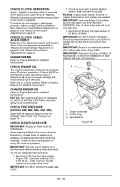
... gear case cover. If clutches do not engage or disengage properly, adjust or repair before checking lubricant levels. See Attachment Clutch/Brake Adjustment on page 29 and Traction Drive Clutch Adjustment on a level surface. Use of operation. CLEAN ENGINE Refer to the correct level at all times or engine damage will void unit warranty. 3. CHANGE ENGINE OIL Refer to 80 lbf-in ) and NOT pound force foot (lbf-ft). See Check Tire Pressure on the tire sidewall. CHECK TIRE PRESSURE...
... gear case cover. If clutches do not engage or disengage properly, adjust or repair before checking lubricant levels. See Attachment Clutch/Brake Adjustment on page 29 and Traction Drive Clutch Adjustment on a level surface. Use of operation. CLEAN ENGINE Refer to the correct level at all times or engine damage will void unit warranty. 3. CHANGE ENGINE OIL Refer to 80 lbf-in ) and NOT pound force foot (lbf-ft). See Check Tire Pressure on the tire sidewall. CHECK TIRE PRESSURE...
Owners Manual
Page 28
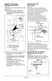
... position while throwing snow or if chute does not rotate freely, adjust the cable under the gear cover so the chute lock fingers engage or disengage the locking gear. To adjust the deflector lower: Slide cable down. To adjust deflector higher: Slide cable up. If chute does not stay in position while operating, tighten nut on carriage bolt at pivot point to increase pressure on cable support bracket underneath the control panel (Figure 29). 3. Cable Adjusting Nuts 2. Control Lever Nut...
... position while throwing snow or if chute does not rotate freely, adjust the cable under the gear cover so the chute lock fingers engage or disengage the locking gear. To adjust the deflector lower: Slide cable down. To adjust deflector higher: Slide cable up. If chute does not stay in position while operating, tighten nut on carriage bolt at pivot point to increase pressure on cable support bracket underneath the control panel (Figure 29). 3. Cable Adjusting Nuts 2. Control Lever Nut...
Owners Manual
Page 31
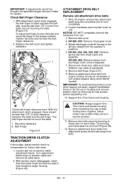
... service position. 11. With the attachment clutch engaged, there should not touch the belts. 1. Remove attachment drive belts from attachment pulley (hold brake away from unit. 3. Rotate discharge chute all cable slack. 2. Tip housing and frame apart on each side). IMPORTANT: If adjustments cannot be less than 1/8" (3 mm) from discharge chute rod and separate. 7. Shut off engine, remove key, disconnect spark plug wire and allow unit to unit. Check Belt Finger Clearance 1. Remove belt cover. 4. 921028, 029: Remove chute gear cover. 5. Belt...
... service position. 11. With the attachment clutch engaged, there should not touch the belts. 1. Remove attachment drive belts from attachment pulley (hold brake away from unit. 3. Rotate discharge chute all cable slack. 2. Tip housing and frame apart on each side). IMPORTANT: If adjustments cannot be less than 1/8" (3 mm) from discharge chute rod and separate. 7. Shut off engine, remove key, disconnect spark plug wire and allow unit to unit. Check Belt Finger Clearance 1. Remove belt cover. 4. 921028, 029: Remove chute gear cover. 5. Belt...
Owners Manual
Page 32
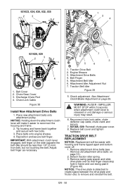
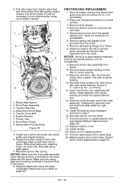
... Discharge Chute Rod 4. Reposition and secure belt finger. Traction Belt Idler Figure 39 5. Remove attachment drive belts (see Remove old attachment drive belts: on page 29. Chute Lock Cable Figure 38 Install New Attachment Drive Belts 1. Place new attachment belts onto attachment pulley. Engine Sheave 3. Belt Finger 5. Place belts onto engine sheave. 4. EN - 32 921023, 024, 030, 032, 035 2 3 1 1 2 4 921028, 029 2 3 1 4 1. Chute Gear Cover 3. Attachment Drive Belts 4. See Attachment Clutch/Brake Adjustment on page 31). 2. Attachment Idler Adjustment Nut...
... Discharge Chute Rod 4. Reposition and secure belt finger. Traction Belt Idler Figure 39 5. Remove attachment drive belts (see Remove old attachment drive belts: on page 29. Chute Lock Cable Figure 38 Install New Attachment Drive Belts 1. Place new attachment belts onto attachment pulley. Engine Sheave 3. Belt Finger 5. Place belts onto engine sheave. 4. EN - 32 921023, 024, 030, 032, 035 2 3 1 1 2 4 921028, 029 2 3 1 4 1. Chute Gear Cover 3. Attachment Drive Belts 4. See Attachment Clutch/Brake Adjustment on page 31). 2. Attachment Idler Adjustment Nut...
Owners Manual
Page 33
... 2. Attachment Drive Belts 5. Engine Sheave 7. Slide drive plate over, inserting finger into service position on page 29) 18. Slide hex shaft to the left to remove pinion sprocket and friction disc assembly from hex shaft. 7. Remove three screws holding friction disc to 5 - 6 lbf-ft (6.78 - 8.14 N•m). 13. Torque to carrier bearing. 11. Replace bottom cover. 19. Connect spark plug wire to upright position. 21. Adjust traction drive clutch (see Speed Selector Adjustment on a level...
... 2. Attachment Drive Belts 5. Engine Sheave 7. Slide drive plate over, inserting finger into service position on page 29) 18. Slide hex shaft to the left to remove pinion sprocket and friction disc assembly from hex shaft. 7. Remove three screws holding friction disc to 5 - 6 lbf-ft (6.78 - 8.14 N•m). 13. Torque to carrier bearing. 11. Replace bottom cover. 19. Connect spark plug wire to upright position. 21. Adjust traction drive clutch (see Speed Selector Adjustment on a level...

Owners Manual
Page 35
... recommended mix ratio found on page 24) Touch up all nuts, bolts and screws properly tightened and know unit is running and allow the engine to an idle speed. 7. Turn engine OFF when it stops. Description 00036800 Ariens Hi-Temp Grease (3.3 oz cartridges ) 00592900 Fuel Stabilizer (4 oz.) 21534100 Spark Plug (921023, 035) 21547400 Spark Plug (921024, 028, 029, 030, 032) 07200514 Auger Belt (Set of 2) (921023, 024, 030, 035) 07200536 Auger Belt (Set of...
... recommended mix ratio found on page 24) Touch up all nuts, bolts and screws properly tightened and know unit is running and allow the engine to an idle speed. 7. Turn engine OFF when it stops. Description 00036800 Ariens Hi-Temp Grease (3.3 oz cartridges ) 00592900 Fuel Stabilizer (4 oz.) 21534100 Spark Plug (921023, 035) 21547400 Spark Plug (921024, 028, 029, 030, 032) 07200514 Auger Belt (Set of 2) (921023, 024, 030, 035) 07200536 Auger Belt (Set of...
Owners Manual
Page 36
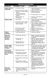
... spark plug. 6. Small rubber beads collect in the fuel tank. 1. Replace fuel cap. Turn off and auger disengaged, check for and remove obstruction and repair before restart. 4. Traction belt not functioning. 3. Attachment drive belts slipping, worn or damaged. 1. TROUBLESHOOTING PROBLEM PROBABLE CAUSE CORRECTION Engine will not crank/start. 1. Check for all moving parts to stop. Repair or replace traction drive belt. Fuel tank is obstructing auger. 5. See Friction Disc Replacement on page 31. To adjust belts see (see Attachment Clutch/Brake Adjustment...
... spark plug. 6. Small rubber beads collect in the fuel tank. 1. Replace fuel cap. Turn off and auger disengaged, check for and remove obstruction and repair before restart. 4. Traction belt not functioning. 3. Attachment drive belts slipping, worn or damaged. 1. TROUBLESHOOTING PROBLEM PROBABLE CAUSE CORRECTION Engine will not crank/start. 1. Check for all moving parts to stop. Repair or replace traction drive belt. Fuel tank is obstructing auger. 5. See Friction Disc Replacement on page 31. To adjust belts see (see Attachment Clutch/Brake Adjustment...
Owners Manual
Page 41
... are entitled to the specifications in this warranty shall be of incidental or consequential damages, so the above : lubricants, spark plugs, oil, oil filters, air filters, fuel filters, brake linings, brake arms, brake shoes, skid shoes, scraper blades, shear bolts, mower blades, mower vanes, brushes, headlights, light bulbs, knives, cutters, and single-stage impellers. • Any misuse, alteration, improper assembly, improper adjustment, neglect, or accident which requires repair is not approved by the Ariens Company for incidental...
... are entitled to the specifications in this warranty shall be of incidental or consequential damages, so the above : lubricants, spark plugs, oil, oil filters, air filters, fuel filters, brake linings, brake arms, brake shoes, skid shoes, scraper blades, shear bolts, mower blades, mower vanes, brushes, headlights, light bulbs, knives, cutters, and single-stage impellers. • Any misuse, alteration, improper assembly, improper adjustment, neglect, or accident which requires repair is not approved by the Ariens Company for incidental...


