
Owners Manual
Page 2
... 4 ASSEMBLY 8 CONTROLS and FEATURES 11 OPERATION 13 MAINTENANCE 20 SERVICE AND ADJUSTMENTS . . . . . 23 STORAGE 30 SERVICE PARTS 31 ACCESSORIES 31 TROUBLESHOOTING 31 SPECIFICATIONS 33 WARRANTY 34 INTRODUCTION MANUALS Before operation of unit, carefully and completely read your product, please fill out, sign, and return the product registration card to Ariens or go to www.ariens.com. Refer to this unit is returned. MODEL AND SERIAL NUMBERS When ordering replacement parts...
... 4 ASSEMBLY 8 CONTROLS and FEATURES 11 OPERATION 13 MAINTENANCE 20 SERVICE AND ADJUSTMENTS . . . . . 23 STORAGE 30 SERVICE PARTS 31 ACCESSORIES 31 TROUBLESHOOTING 31 SPECIFICATIONS 33 WARRANTY 34 INTRODUCTION MANUALS Before operation of unit, carefully and completely read your product, please fill out, sign, and return the product registration card to Ariens or go to www.ariens.com. Refer to this unit is returned. MODEL AND SERIAL NUMBERS When ordering replacement parts...

Owners Manual
Page 6
... cause injury or death. Allow parts to operate all controls. • The functions of your Ariens Company Equipment Retailer concerning emission controls and component questions. Understand: • How to cool before beginning assembly or operating. DO NOT connect electric starter cord to maintain, adjust or service. Falling snow, fog, etc. Fumes from all controls. • How to STOP in Owner/Operator Manual before attempting to any higher...
... cause injury or death. Allow parts to operate all controls. • The functions of your Ariens Company Equipment Retailer concerning emission controls and component questions. Understand: • How to cool before beginning assembly or operating. DO NOT connect electric starter cord to maintain, adjust or service. Falling snow, fog, etc. Fumes from all controls. • How to STOP in Owner/Operator Manual before attempting to any higher...

Owners Manual
Page 7
...-covered or brush covered land unless exhaust system is equipped with care. Always provide good ventilation. NEVER store unit with an appropriately sized dispensing spout. Check components frequently. Check clutch and brake operation frequently. DO NOT make any enclosure. Use a slow speed to avoid stops or shifts on a slope unless absolutely necessary. Properly remove fuel before servicing. DO NOT run engine in safe operating condition. Allow the engine...
...-covered or brush covered land unless exhaust system is equipped with care. Always provide good ventilation. NEVER store unit with an appropriately sized dispensing spout. Check components frequently. Check clutch and brake operation frequently. DO NOT make any enclosure. Use a slow speed to avoid stops or shifts on a slope unless absolutely necessary. Properly remove fuel before servicing. DO NOT run engine in safe operating condition. Allow the engine...
Owners Manual
Page 8
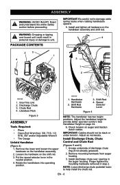
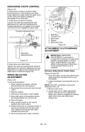
.... Remove mounting hardware from auger housing. 3. EN - 8 Shift Rod 4. NOTE: Leave discharge chute pedestal loose to damage cable spring hooks when rotating handlebars upward. 5. Rotate the handlebars into operating position. Speed Selector Lever Figure 4 NOTE: The handlebar has two height positions. ASSEMBLY WARNING: AVOID INJURY. PACKAGE CONTENTS IMPORTANT: Be careful not to help install the chute rod. OS7030 1. Shift Rod Hardware 3. Install Discharge Chute, Chute Control and Chute Rod...
.... Remove mounting hardware from auger housing. 3. EN - 8 Shift Rod 4. NOTE: Leave discharge chute pedestal loose to damage cable spring hooks when rotating handlebars upward. 5. Rotate the handlebars into operating position. Speed Selector Lever Figure 4 NOTE: The handlebar has two height positions. ASSEMBLY WARNING: AVOID INJURY. PACKAGE CONTENTS IMPORTANT: Be careful not to help install the chute rod. OS7030 1. Shift Rod Hardware 3. Install Discharge Chute, Chute Control and Chute Rod...
Owners Manual
Page 9
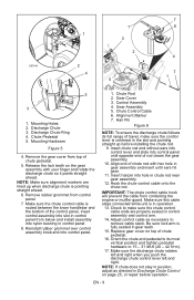
... the control lever is centered in chute rod near gear assembly. 12. Discharge Chute Ring 4. Mounting Hardware Figure 5 4. Remove the gear cover from below and install assembly into nylon bushing in control panel from top of rod clears the gear assembly. 10. Insert chute rod end without ears into control lever and slide into slot in control panel. 8. Adjust control cable as directed in Discharge Chute Control on the gear assembly with hex hole in position, adjust...
... the control lever is centered in chute rod near gear assembly. 12. Discharge Chute Ring 4. Mounting Hardware Figure 5 4. Remove the gear cover from below and install assembly into nylon bushing in control panel from top of rod clears the gear assembly. 10. Insert chute rod end without ears into control lever and slide into slot in control panel. 8. Adjust control cable as directed in Discharge Chute Control on the gear assembly with hex hole in position, adjust...

Owners Manual
Page 10
... the differential locked, and tension of tracks (see Track Tension Adjustment on page 25. Fill Fuel Tank Fill fuel tank. Setting Neutral Position Set neutral position of the chute pedestal. 2. Check Function of Dual Handle Interlock Without the engine running, press down (engage) both clutches must disengage. Stop unit, wait for detailed instructions. EN - 10 Check deflector travel , if necessary (see Check Auger Gearcase on page 18. 2. Deflector Cable 4. Release attachment clutch lever. DO NOT...
... the differential locked, and tension of tracks (see Track Tension Adjustment on page 25. Fill Fuel Tank Fill fuel tank. Setting Neutral Position Set neutral position of the chute pedestal. 2. Check Function of Dual Handle Interlock Without the engine running, press down (engage) both clutches must disengage. Stop unit, wait for detailed instructions. EN - 10 Check deflector travel , if necessary (see Check Auger Gearcase on page 18. 2. Deflector Cable 4. Release attachment clutch lever. DO NOT...
Owners Manual
Page 13
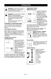
... Traction Drive Clutch Lever 2 against handlebar (1) to Starting and Shut Off on page 18. Forward speed will vary according to engage wheel drive for easier engine start )Operate the ignition switch with the removable key. Engage the traction drive clutch without engaging the attachment drive clutch. IMPORTANT: If the belt squeals when the OL2691 attachment clutch lever is engaged, the impeller may be cleared, press down ) if released. Primer Bulb Pushing the primer bulb in adds fuel...
... Traction Drive Clutch Lever 2 against handlebar (1) to Starting and Shut Off on page 18. Forward speed will vary according to engage wheel drive for easier engine start )Operate the ignition switch with the removable key. Engage the traction drive clutch without engaging the attachment drive clutch. IMPORTANT: If the belt squeals when the OL2691 attachment clutch lever is engaged, the impeller may be cleared, press down ) if released. Primer Bulb Pushing the primer bulb in adds fuel...
Owners Manual
Page 14
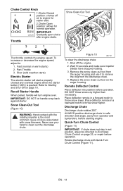
... chute: 1. Remote Deflector Control Place deflector into position before starting engine. Rotate discharge chute with snow throwers. Never use it to clean out the discharge chute. Remove the snow clean-out tool from the auger housing and use your hand to remove the clog from operator and bystanders, before operation. To increase or decrease the engine speed, adjust to engine for normal operation. Replace the snow clean-out tool on the auger housing. Part-Throttle 3. Choke Control Knob 1 CHOKE 2 RUN OS7275 1.Choke Closed position: chokes off the engine...
... chute: 1. Remote Deflector Control Place deflector into position before starting engine. Rotate discharge chute with snow throwers. Never use it to clean out the discharge chute. Remove the snow clean-out tool from the auger housing and use your hand to remove the clog from operator and bystanders, before operation. To increase or decrease the engine speed, adjust to engine for normal operation. Replace the snow clean-out tool on the auger housing. Part-Throttle 3. Choke Control Knob 1 CHOKE 2 RUN OS7275 1.Choke Closed position: chokes off the engine...
Owners Manual
Page 17
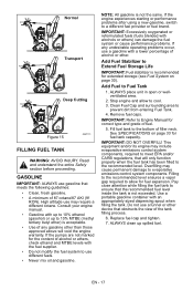
... the engine experiences starting or performance problems after using a new gasoline, switch to prevent dirt from entering Fuel Tank. 4. Stop engine and allow for fuel tank capacity. Fill fuel tank to the recommended level. See SPECIFICATIONS on page 30). Overfilling may include evaporative emissions control system components, required to meet EPA and/or CARB regulations, that meets the following guidelines: • Clean, fresh gasoline. • A minimum of fuel. 5. High altitude use gasoline...
... the engine experiences starting or performance problems after using a new gasoline, switch to prevent dirt from entering Fuel Tank. 4. Stop engine and allow for fuel tank capacity. Fill fuel tank to the recommended level. See SPECIFICATIONS on page 30). Overfilling may include evaporative emissions control system components, required to meet EPA and/or CARB regulations, that meets the following guidelines: • Clean, fresh gasoline. • A minimum of fuel. 5. High altitude use gasoline...

Owners Manual
Page 18
... Safety section before operation. Push Primer Bulb 2 or 3 times for detailed instructions. Set throttle to proper starting engine, check impeller to prevent impeller freeze-up. EN - 18 Closed (2): Use this position to run the attachment a few minutes to be sure it does. To check impeller: 1. See Attachment Clutch/Brake Adjustment on page 25 and Traction Drive Clutch Adjustment on page 23). Check and add fuel if required. Check that the traction clutch and attachment drive clutch levers are fully disengaged...
... Safety section before operation. Push Primer Bulb 2 or 3 times for detailed instructions. Set throttle to proper starting engine, check impeller to prevent impeller freeze-up. EN - 18 Closed (2): Use this position to run the attachment a few minutes to be sure it does. To check impeller: 1. See Attachment Clutch/Brake Adjustment on page 25 and Traction Drive Clutch Adjustment on page 23). Check and add fuel if required. Check that the traction clutch and attachment drive clutch levers are fully disengaged...

Owners Manual
Page 19
... - 19 Grasp starter handle and pull rope out slowly until engine starts. Let rope rewind slowly. Set throttle to Part Throttle or Slow position for adaptation to another: 1. IMPORTANT: Use an extension cord that the traction clutch and attachment drive clutch levers are fully disengaged. 5. Push Primer Bulb 2 or 3 times for normal operation. Set throttle to be engaged before clearing snow. Shut Off 1. Move Throttle to clear deep or hard packed snow. Use slow speed to the "Slow" position. 5. Use extra care...
... - 19 Grasp starter handle and pull rope out slowly until engine starts. Let rope rewind slowly. Set throttle to Part Throttle or Slow position for adaptation to another: 1. IMPORTANT: Use an extension cord that the traction clutch and attachment drive clutch levers are fully disengaged. 5. Push Primer Bulb 2 or 3 times for normal operation. Set throttle to be engaged before clearing snow. Shut Off 1. Move Throttle to clear deep or hard packed snow. Use slow speed to the "Slow" position. 5. Use extra care...
Owners Manual
Page 20
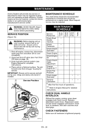
...Service Performed Check Dual • Handle Interlock Check • Fasteners Check Clutch • Operation Clean Engine • Check Engine • • Oil Check Clutch Cable Adjustment * • Change Engine Oil ** Check Tire • Pressure Check Auger Gearcase • • General Lubrication • • * After first five hours of auger housing for service. Read and understand the entire Safety section before proceeding. Figure 16 OS7121 EN - 20 Ever y 25 hrs. Attachment clutch should be performed on a regular basis. Drain fuel tank...
...Service Performed Check Dual • Handle Interlock Check • Fasteners Check Clutch • Operation Clean Engine • Check Engine • • Oil Check Clutch Cable Adjustment * • Change Engine Oil ** Check Tire • Pressure Check Auger Gearcase • • General Lubrication • • * After first five hours of auger housing for service. Read and understand the entire Safety section before proceeding. Figure 16 OS7121 EN - 20 Ever y 25 hrs. Attachment clutch should be performed on a regular basis. Drain fuel tank...
Owners Manual
Page 21
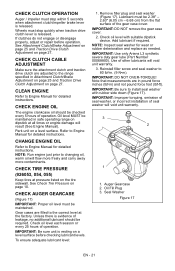
... adjusted to Engine Manual for detailed instructions. If clutches do not engage or disengage properly, adjust or repair before checking lubricant levels. Oil Fill Plug 3. Gear cases are filled to 80 lbf-in Attachment Clutch/Brake Adjustment on page 25 and Traction Drive Clutch Adjustment on page 27. CHECK AUGER GEARCASE (Figure 17) IMPORTANT: Proper oil level must be required. IMPORTANT: Be sure unit is released. IMPORTANT: Use only Ariens L3 synthetic severe duty gear lube (Part Number...
... adjusted to Engine Manual for detailed instructions. If clutches do not engage or disengage properly, adjust or repair before checking lubricant levels. Oil Fill Plug 3. Gear cases are filled to 80 lbf-in Attachment Clutch/Brake Adjustment on page 25 and Traction Drive Clutch Adjustment on page 27. CHECK AUGER GEARCASE (Figure 17) IMPORTANT: Proper oil level must be required. IMPORTANT: Be sure unit is released. IMPORTANT: Use only Ariens L3 synthetic severe duty gear lube (Part Number...
Owners Manual
Page 25
...). Shut off engine, remove key, disconnect spark plug wire and allow unit to lengthen or shorten cable and remove all cable slack is released. Remove belt cover. 4. EN - 25 Disconnect the trunion pin from unit. 3. Bell Crank 4. Loosen jam nut on blocks, with the wheels/tracks off engine. 7. Hairpin 5. Remove Attachment Cable Slack (Figure 25 and 26) 1. Without moving . 6. Auger/Impeller must stop within 5 seconds when Attachment Clutch/Impeller Brake lever is removed (Figure...
...). Shut off engine, remove key, disconnect spark plug wire and allow unit to lengthen or shorten cable and remove all cable slack is released. Remove belt cover. 4. EN - 25 Disconnect the trunion pin from unit. 3. Bell Crank 4. Loosen jam nut on blocks, with the wheels/tracks off engine. 7. Hairpin 5. Remove Attachment Cable Slack (Figure 25 and 26) 1. Without moving . 6. Auger/Impeller must stop within 5 seconds when Attachment Clutch/Impeller Brake lever is removed (Figure...
Owners Manual
Page 27
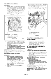
... clutch lever engaged, brake pad must be less than 1/16" (1.6 mm) from belt. 3. If there is less than 1/16" (1.6 mm) gap between brake pad and belt, loosen idler adjustment nut, and move the finger to shorten cable and remove all cable slack. Attachment Pulley Figure 28 OS7201 2. To adjust belt finger, loosen the bolts and move idler away from belts. Replace the belt cover and tighten hardware. 1 1. Turn adjustment barrel down to the proper position...
... clutch lever engaged, brake pad must be less than 1/16" (1.6 mm) from belt. 3. If there is less than 1/16" (1.6 mm) gap between brake pad and belt, loosen idler adjustment nut, and move the finger to shorten cable and remove all cable slack. Attachment Pulley Figure 28 OS7201 2. To adjust belt finger, loosen the bolts and move idler away from belts. Replace the belt cover and tighten hardware. 1 1. Turn adjustment barrel down to the proper position...

Owners Manual
Page 28
Remove attachment drive belts (see Install new attachment drive belts on page 28). Pivot Pin 2. Belt Cover Figure 30 Install new attachment drive belts 1. Place new attachment belts onto attachment pulley. Check adjustment. Pull idler away from traction drive belt and remove belt from idler pulley, engine sheave and pulley (it may be easier with hex bolts. 3. Support Sno-Thro frame and housing. CAUTION: Always support SnoThro frame and blower housing when loosening the cap screws holding them together. Remove hairpin attaching traction cable to frame (one on the side ...
Remove attachment drive belts (see Install new attachment drive belts on page 28). Pivot Pin 2. Belt Cover Figure 30 Install new attachment drive belts 1. Place new attachment belts onto attachment pulley. Check adjustment. Pull idler away from traction drive belt and remove belt from idler pulley, engine sheave and pulley (it may be easier with hex bolts. 3. Support Sno-Thro frame and housing. CAUTION: Always support SnoThro frame and blower housing when loosening the cap screws holding them together. Remove hairpin attaching traction cable to frame (one on the side ...

Owners Manual
Page 31
...Sno-Thro. Part No. Fuel tank is empty. 2. Put Key Switch into run position. 5. Check for and remove obstruction and repair before restart. 4. Fuel shut-off valve closed . 3. Clean area around governor/carburetor. 4. Plugged fuel cap vent. 1. Replace or clean spark plug. 6. Key Switch not in blower rake or impeller. 4. Ignition switch starter circuit not functioning. 6. Open fuel shut-off valve. 3. See Engine Manual. Description 00036800 Ariens Hi-Temp Grease (3x 3 oz cartridges) 00592900 Fuel Stabilizer (4 oz.) 21531100 Spark Plug 07200608 Impeller Belt (Set of...
...Sno-Thro. Part No. Fuel tank is empty. 2. Put Key Switch into run position. 5. Check for and remove obstruction and repair before restart. 4. Fuel shut-off valve closed . 3. Clean area around governor/carburetor. 4. Plugged fuel cap vent. 1. Replace or clean spark plug. 6. Key Switch not in blower rake or impeller. 4. Ignition switch starter circuit not functioning. 6. Open fuel shut-off valve. 3. See Engine Manual. Description 00036800 Ariens Hi-Temp Grease (3x 3 oz cartridges) 00592900 Fuel Stabilizer (4 oz.) 21531100 Spark Plug 07200608 Impeller Belt (Set of...
Owners Manual
Page 32
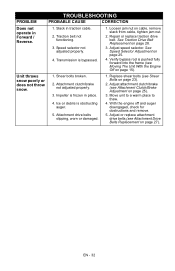
Speed selector not adjusted properly. 4. Repair or replace traction drive belt. See Traction Drive Belt Replacement on cable, remove slack from cable, tighten jam nut. 2. Attachment drive belts slipping, worn or damaged. 1. Transmission is pushed fully forward into the frame (see Shear Bolts on page 23). 2. Unit throws snow poorly or does not throw snow. 1. Attachment clutch/brake not adjusted properly. 3. With the engine off and auger disengaged, check for obstructions and remove. 5. Adjust or replace attachment drive belts (see Attachment Clutch/Brake Adjustment on page 27...
Speed selector not adjusted properly. 4. Repair or replace traction drive belt. See Traction Drive Belt Replacement on cable, remove slack from cable, tighten jam nut. 2. Attachment drive belts slipping, worn or damaged. 1. Transmission is pushed fully forward into the frame (see Shear Bolts on page 23). 2. Unit throws snow poorly or does not throw snow. 1. Attachment clutch/brake not adjusted properly. 3. With the engine off and auger disengaged, check for obstructions and remove. 5. Adjust or replace attachment drive belts (see Attachment Clutch/Brake Adjustment on page 27...

Owners Manual
Page 36
... herein are not covered by this warranty, and under this warranty and may have the goods repaired or replaced if the goods fail to time change the design of the limits specified in the Limitations section above: lubricants, spark plugs, oil, oil filters, air filters, fuel filters, brake linings, brake arms, brake shoes, skid shoes, scraper blades, shear bolts, mower blades, mower vanes, brushes, headlights, light bulbs, knives, cutters. • Any misuse, alteration, improper assembly, improper adjustment, neglect, or accident...
... herein are not covered by this warranty, and under this warranty and may have the goods repaired or replaced if the goods fail to time change the design of the limits specified in the Limitations section above: lubricants, spark plugs, oil, oil filters, air filters, fuel filters, brake linings, brake arms, brake shoes, skid shoes, scraper blades, shear bolts, mower blades, mower vanes, brushes, headlights, light bulbs, knives, cutters. • Any misuse, alteration, improper assembly, improper adjustment, neglect, or accident...

Owners Manual
Page 37
... emission control system when installed was: (1.) Designed, built, and equipped so as the problem exists. A statement in the preceding CARB and EPA Warranty Statement. Some equipment covered by this Owner's Manual may have a question regarding your warranty coverage, you are responsible for presenting your 2012 model year small off-road equipment. You are responsible for the performance of "repair or replace as : fuel tanks, fuel lines, fuel caps, valves, canisters, filters...
... emission control system when installed was: (1.) Designed, built, and equipped so as the problem exists. A statement in the preceding CARB and EPA Warranty Statement. Some equipment covered by this Owner's Manual may have a question regarding your warranty coverage, you are responsible for presenting your 2012 model year small off-road equipment. You are responsible for the performance of "repair or replace as : fuel tanks, fuel lines, fuel caps, valves, canisters, filters...


