
Owners Manual
Page 2
... Engine Model and Serial numbers here. If used improperly, this unit could be honored, whether or not the product registration card is included in the unit literature package. EN - 2 ENGINE MANUAL The engine on this manual for a replacement manual. Refer to www.ariens.com. Keep a proof of purchase. TABLE OF CONTENTS SAFETY 4 ASSEMBLY 8 CONTROLS and FEATURES 11 OPERATION 13 MAINTENANCE 20 SERVICE AND ADJUSTMENTS . . . . . 23 STORAGE 30 SERVICE PARTS 31...
... Engine Model and Serial numbers here. If used improperly, this unit could be honored, whether or not the product registration card is included in the unit literature package. EN - 2 ENGINE MANUAL The engine on this manual for a replacement manual. Refer to www.ariens.com. Keep a proof of purchase. TABLE OF CONTENTS SAFETY 4 ASSEMBLY 8 CONTROLS and FEATURES 11 OPERATION 13 MAINTENANCE 20 SERVICE AND ADJUSTMENTS . . . . . 23 STORAGE 30 SERVICE PARTS 31...

Owners Manual
Page 6
... attachment, stop before assembly, maintenance or service. NEVER ATTEMPT TO UNCLOG OR CLEAN UNIT WHILE ENGINE IS RUNNING. DO NOT wear loose clothing or jewelry and tie back hair that may result in . Never direct discharge towards persons or property that may be thrown from spark plug before leaving operator's position. Be alert and shut off body parts. ALWAYS remove key and/or wire...
... attachment, stop before assembly, maintenance or service. NEVER ATTEMPT TO UNCLOG OR CLEAN UNIT WHILE ENGINE IS RUNNING. DO NOT wear loose clothing or jewelry and tie back hair that may result in . Never direct discharge towards persons or property that may be thrown from spark plug before leaving operator's position. Be alert and shut off body parts. ALWAYS remove key and/or wire...

Owners Manual
Page 7
... -speed engine. DO NOT run engine in reverse unless absolutely necessary. Damaged or worn out muffler can damage unit. Maintain or replace safety and instruction labels, as necessary. Disengage attachment drive when traveling from engine exhaust can cause injury or death. Never leave a running . ALWAYS shut off engine, remove key, and close fuel shut-off fuel and allow engine to stop unit and engine. Properly remove fuel before servicing. Check clutch and brake operation...
... -speed engine. DO NOT run engine in reverse unless absolutely necessary. Damaged or worn out muffler can damage unit. Maintain or replace safety and instruction labels, as necessary. Disengage attachment drive when traveling from engine exhaust can cause injury or death. Never leave a running . ALWAYS shut off engine, remove key, and close fuel shut-off fuel and allow engine to stop unit and engine. Properly remove fuel before servicing. Check clutch and brake operation...
Owners Manual
Page 8
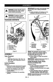
... not to unit. Chute Rod 4. Finger tighten the mounting hardware removed in the neutral position. 4. Literature Pack Figure 3 ASSEMBLY Tools Required: • Pliers • Open-End Wrenches: 3/8, 7/16, 1/2, 9/16, 3/4" and/or Adjustable Wrench • Tire Gauge Unfold Handlebar (Figure 4) 1. Loosen the hardware on auger and traction clutch cables. Handlebar Hardware 2. Check tension on the shift rod. 3. Install Discharge Chute, Chute Control and Chute Rod (Figures 5 and...
... not to unit. Chute Rod 4. Finger tighten the mounting hardware removed in the neutral position. 4. Literature Pack Figure 3 ASSEMBLY Tools Required: • Pliers • Open-End Wrenches: 3/8, 7/16, 1/2, 9/16, 3/4" and/or Adjustable Wrench • Tire Gauge Unfold Handlebar (Figure 4) 1. Loosen the hardware on auger and traction clutch cables. Handlebar Hardware 2. Check tension on the shift rod. 3. Install Discharge Chute, Chute Control and Chute Rod (Figures 5 and...
Owners Manual
Page 9
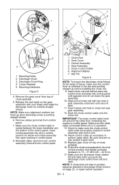
.... 6. Adjust control cable as directed in control assembly and control arm. 14. EN - 9 Remove the gear cover from top of the control panel, insert control assembly into slot in control panel from below and install assembly into control panel. 1. Make sure the discharge chute rotates left and right when you push the discharge chute control lever left and right. Check to 15 - 31 lbf-ft (20 - 42 N•m). 17. Replace gear cover on the gear assembly...
.... 6. Adjust control cable as directed in control assembly and control arm. 14. EN - 9 Remove the gear cover from top of the control panel, insert control assembly into slot in control panel from below and install assembly into control panel. 1. Make sure the discharge chute rotates left and right when you push the discharge chute control lever left and right. Check to 15 - 31 lbf-ft (20 - 42 N•m). 17. Replace gear cover on the gear assembly...

Owners Manual
Page 10
... of chute deflector (Figure 7). 3. See Speed Selector Adjustment on page 21). Refer to perform the job. • Do not inflate the tires above the recommended pressure. • Do not weld or heat a wheel and tire assembly. Check Engine Crankcase Oil IMPORTANT: The engine may be shipped with the differential locked, and tension of unit with oil in Attachment Belt 1. Attachment clutch should remain engaged until traction clutch lever...
... of chute deflector (Figure 7). 3. See Speed Selector Adjustment on page 21). Refer to perform the job. • Do not inflate the tires above the recommended pressure. • Do not weld or heat a wheel and tire assembly. Check Engine Crankcase Oil IMPORTANT: The engine may be shipped with the differential locked, and tension of unit with oil in Attachment Belt 1. Attachment clutch should remain engaged until traction clutch lever...
Owners Manual
Page 13
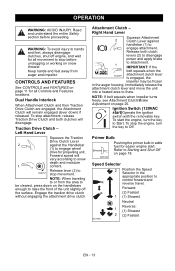
.... Attachment Clutch - OS7320 Speed Selector 2 Position the Speed Selector in the appropriate position to attachment. Keep hands and feet away from the area to be frozen in adds fuel for all Controls and Features locations. Release lever (2) to OL2701 stop the engine, turn the key to snow depth and moisture 1 content. Release both clutches will remain engaged (lever down on page 18. Primer Bulb Pushing the primer bulb in the auger housing...
.... Attachment Clutch - OS7320 Speed Selector 2 Position the Speed Selector in the appropriate position to attachment. Keep hands and feet away from the area to be frozen in adds fuel for all Controls and Features locations. Release lever (2) to OL2701 stop the engine, turn the key to snow depth and moisture 1 content. Release both clutches will remain engaged (lever down on page 18. Primer Bulb Pushing the primer bulb in the auger housing...
Owners Manual
Page 14
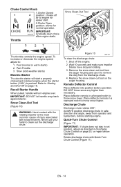
Choke Control Knob 1 CHOKE 2 RUN OS7275 1.Choke Closed position: chokes off the engine. 2. Fast (normal or warm starts) 2. Wait 10 seconds and make sure impeller blades have stopped rotating. 3. Discharge Chute Discharge chute rotates 200°. To increase or decrease the engine speed, adjust to engine for normal operation. Replace the snow clean-out tool on page 25, or repair before operation. IMPORTANT: DO NOT let handle snap back against starter. Snow Clean-Out Tool (Figure 10) WARNING: Hand contact...
Choke Control Knob 1 CHOKE 2 RUN OS7275 1.Choke Closed position: chokes off the engine. 2. Fast (normal or warm starts) 2. Wait 10 seconds and make sure impeller blades have stopped rotating. 3. Discharge Chute Discharge chute rotates 200°. To increase or decrease the engine speed, adjust to engine for normal operation. Replace the snow clean-out tool on page 25, or repair before operation. IMPORTANT: DO NOT let handle snap back against starter. Snow Clean-Out Tool (Figure 10) WARNING: Hand contact...
Owners Manual
Page 17
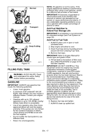
... entering Fuel Tank. 4. IMPORTANT: Refer to the recommended level. This equipment and/or its engine may include evaporative emissions control system components, required to meet EPA and/or CARB regulations, that obstructs the view of alcohol or ether. Stop engine and allow for fuel tank capacity. Remove fuel caps. See SPECIFICATIONS on page 30). Replace fuel cap and tighten. 7. High altitude use different fuels. • Never mix oil and gasoline. Fill fuel tank to...
... entering Fuel Tank. 4. IMPORTANT: Refer to the recommended level. This equipment and/or its engine may include evaporative emissions control system components, required to meet EPA and/or CARB regulations, that obstructs the view of alcohol or ether. Stop engine and allow for fuel tank capacity. Remove fuel caps. See SPECIFICATIONS on page 30). Replace fuel cap and tighten. 7. High altitude use different fuels. • Never mix oil and gasoline. Fill fuel tank to...

Owners Manual
Page 18
... clearing snow. Push Primer Bulb 2 or 3 times for detailed instructions. Set throttle to run the attachment a few minutes to service, transport, or store the unit. 2 PRE-START 1. Turn on engine shut-off valve 1 has two positions: Open (1): Use this time. Allow 7/8 in. (22mm) between scraper blade and hard, smooth surface(s). Read entire Owner/Operator Manual and the Engine Manual first. See Engine Manual for cold engine. The fuel shut-off switch ("ON"). 7. Check Dual Handle Interlock Without the engine running to see Differential Lock...
... clearing snow. Push Primer Bulb 2 or 3 times for detailed instructions. Set throttle to run the attachment a few minutes to service, transport, or store the unit. 2 PRE-START 1. Turn on engine shut-off valve 1 has two positions: Open (1): Use this time. Allow 7/8 in. (22mm) between scraper blade and hard, smooth surface(s). Read entire Owner/Operator Manual and the Engine Manual first. See Engine Manual for cold engine. The fuel shut-off switch ("ON"). 7. Check Dual Handle Interlock Without the engine running to see Differential Lock...

Owners Manual
Page 19
... Starter Handle snap against Starter. 10. Set Throttle to each side, so snow is cold, apply choke. Let rope rewind slowly. 9. Make sure that could be needed . 12. Release Traction Drive Clutch Lever and allow unit to come to Fast position for recommended extension cord. 3. Turn on engine shut-off valve when transporting unit on handlebars enough to a complete stop . 4. SNOW REMOVAL IMPORTANT: Allow unit and engine to adjust to TROUBLESHOOTING on engine...
... Starter Handle snap against Starter. 10. Set Throttle to each side, so snow is cold, apply choke. Let rope rewind slowly. 9. Make sure that could be needed . 12. Release Traction Drive Clutch Lever and allow unit to come to Fast position for recommended extension cord. 3. Turn on engine shut-off valve when transporting unit on handlebars enough to a complete stop . 4. SNOW REMOVAL IMPORTANT: Allow unit and engine to adjust to TROUBLESHOOTING on engine...
Owners Manual
Page 20
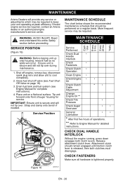
... service. Place unit on page 18). 3. Service Position MAINTENANCE SCHEDULE The chart below shows the recommended maintenance schedule that should remain engaged until traction clutch lever is tightened properly. Drain fuel tank and fuel system (see Fuel ShutOff Valve on a flat level surface. Yearly Service Performed Check Dual • Handle Interlock Check • Fasteners Check Clutch • Operation Clean Engine • Check Engine • • Oil Check Clutch Cable Adjustment * • Change Engine Oil ** Check Tire • Pressure Check Auger...
... service. Place unit on page 18). 3. Service Position MAINTENANCE SCHEDULE The chart below shows the recommended maintenance schedule that should remain engaged until traction clutch lever is tightened properly. Drain fuel tank and fuel system (see Fuel ShutOff Valve on a flat level surface. Yearly Service Performed Check Dual • Handle Interlock Check • Fasteners Check Clutch • Operation Clean Engine • Check Engine • • Oil Check Clutch Cable Adjustment * • Change Engine Oil ** Check Tire • Pressure Check Auger...
Owners Manual
Page 21
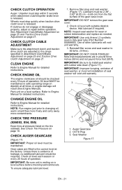
... Pressure on a level surface. Note that measurements are in pound force inches (lbf-in . (9 N•m). If clutches do not engage or disengage properly, adjust or repair before checking lubricant levels. CHECK CLUTCH CABLE ADJUSTMENT Make sure the attachment clutch and traction drive clutch are filled to install seal washer with suitable dipstick device. Gear cases are adjusted to Engine Manual for detailed instructions. Check oil level each season or every 25 hours of the gear case cover...
... Pressure on a level surface. Note that measurements are in pound force inches (lbf-in . (9 N•m). If clutches do not engage or disengage properly, adjust or repair before checking lubricant levels. CHECK CLUTCH CABLE ADJUSTMENT Make sure the attachment clutch and traction drive clutch are filled to install seal washer with suitable dipstick device. Gear cases are adjusted to Engine Manual for detailed instructions. Check oil level each season or every 25 hours of the gear case cover...
Owners Manual
Page 25
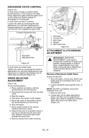
... gear cover so the chute lock fingers engage or disengage the locking gear. Move speed control to lengthen or shorten cable and remove all cable slack is released. Remove blocks from the bell crank. 3. Auger/Impeller must stop within 5 seconds when Attachment Clutch/Impeller Brake lever is removed (Figure 23). NOTE: DO NOT completely remove the hardware from unit. 3. Start the engine. 4. Shut off engine, remove key, disconnect spark plug wire and allow unit to the position...
... gear cover so the chute lock fingers engage or disengage the locking gear. Move speed control to lengthen or shorten cable and remove all cable slack is released. Remove blocks from the bell crank. 3. Auger/Impeller must stop within 5 seconds when Attachment Clutch/Impeller Brake lever is removed (Figure 23). NOTE: DO NOT completely remove the hardware from unit. 3. Start the engine. 4. Shut off engine, remove key, disconnect spark plug wire and allow unit to the position...
Owners Manual
Page 27
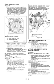
Check Attachment Brake (Figure 28) 1. If there is more than 1/16" (1.6 mm) gap, go to Check Belt Finger Clearance on traction cable adjustment barrel. Attachment Pulley Figure 28 OS7201 2. Check Belt Finger Clearance (Figure 29) 1. Loosen jam nut on page 27. Shut off engine, remove key, disconnect spark plug wire and allow unit to unit (Figure 30). IMPORTANT: Disconnect chute lock cable and deflector cable. 6. IMPORTANT: Use care when rotating the belt fingers. With clutch lever engaged...
Check Attachment Brake (Figure 28) 1. If there is more than 1/16" (1.6 mm) gap, go to Check Belt Finger Clearance on traction cable adjustment barrel. Attachment Pulley Figure 28 OS7201 2. Check Belt Finger Clearance (Figure 29) 1. Loosen jam nut on page 27. Shut off engine, remove key, disconnect spark plug wire and allow unit to unit (Figure 30). IMPORTANT: Disconnect chute lock cable and deflector cable. 6. IMPORTANT: Use care when rotating the belt fingers. With clutch lever engaged...

Owners Manual
Page 28
... pulley (it may be easier with spring clip. Adjust belt finger as necessary. 5. CAUTION: Always support SnoThro frame and blower housing when loosening the cap screws holding them together. 7. IMPORTANT: To avoid bending bottom cover when tipping unit apart, support handlebars firmly or tip unit up on the side opposite the belt idler should be necessary to turn engine sheave using recoil handle). 4. Replace chute gear cover. 8. Housing Cap Screws 3. Belt Cover Figure 30 Install new attachment drive belts 1. Traction Drive Belt...
... pulley (it may be easier with spring clip. Adjust belt finger as necessary. 5. CAUTION: Always support SnoThro frame and blower housing when loosening the cap screws holding them together. 7. IMPORTANT: To avoid bending bottom cover when tipping unit apart, support handlebars firmly or tip unit up on the side opposite the belt idler should be necessary to turn engine sheave using recoil handle). 4. Replace chute gear cover. 8. Housing Cap Screws 3. Belt Cover Figure 30 Install new attachment drive belts 1. Traction Drive Belt...

Owners Manual
Page 31
... or clean spark plug. 6. Replace fuel cap. 1. See Engine Manual. SERVICE PARTS Order the following parts through your Sno-Thro. Description 72406500 Front Weight Kit 72406900 Slicer Bar 72600300 Composite Skid Shoes 72601500 Cover 72408000 Snow Cab PROBLEM Engine will not crank/start. Engine problems. TROUBLESHOOTING PROBABLE CAUSE CORRECTION 1. Fuel tank is empty. 2. Build up of dirt and residue around governor/carburetor. 4. Clean area around governor/carburetor. 4. Mechanical jam in run position. 5. Open fuel shut-off valve. 3. Turn off valve closed . 3. Electric...
... or clean spark plug. 6. Replace fuel cap. 1. See Engine Manual. SERVICE PARTS Order the following parts through your Sno-Thro. Description 72406500 Front Weight Kit 72406900 Slicer Bar 72600300 Composite Skid Shoes 72601500 Cover 72408000 Snow Cab PROBLEM Engine will not crank/start. Engine problems. TROUBLESHOOTING PROBABLE CAUSE CORRECTION 1. Fuel tank is empty. 2. Build up of dirt and residue around governor/carburetor. 4. Clean area around governor/carburetor. 4. Mechanical jam in run position. 5. Open fuel shut-off valve. 3. Turn off valve closed . 3. Electric...
Owners Manual
Page 32
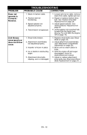
... the engine off and auger disengaged, check for obstructions and remove. 5. Traction belt not functioning. 3. Speed selector not adjusted properly. 4. See Traction Drive Belt Replacement on page 23). 2. Verify bypass rod is frozen in traction cable. 2. Replace shear bolts (see Attachment Clutch/Brake Adjustment on page 27). Unit throws snow poorly or does not throw snow. 1. Move unit to a warm place to thaw. 4. Repair or replace traction drive belt. Shear bolts broken. 2. Transmission is obstructing auger. 5. Adjust attachment clutch/brake (see Shear Bolts...
... the engine off and auger disengaged, check for obstructions and remove. 5. Traction belt not functioning. 3. Speed selector not adjusted properly. 4. See Traction Drive Belt Replacement on page 23). 2. Verify bypass rod is frozen in traction cable. 2. Replace shear bolts (see Attachment Clutch/Brake Adjustment on page 27). Unit throws snow poorly or does not throw snow. 1. Move unit to a warm place to thaw. 4. Repair or replace traction drive belt. Shear bolts broken. 2. Transmission is obstructing auger. 5. Adjust attachment clutch/brake (see Shear Bolts...

Owners Manual
Page 36
..., spark plugs, oil, oil filters, air filters, fuel filters, brake linings, brake arms, brake shoes, skid shoes, scraper blades, shear bolts, mower blades, mower vanes, brushes, headlights, light bulbs, knives, cutters. • Any misuse, alteration, improper assembly, improper adjustment, neglect, or accident which the unit was originally distributed. LIMITATION OF REMEDY AND DAMAGES Ariens Company's liability under this warranty shall be construed as a high pressure hose, spray wand, nozzles, trigger handle, supply hoses, quick couplers, gaskets, valves, pistons, pump valve...
..., spark plugs, oil, oil filters, air filters, fuel filters, brake linings, brake arms, brake shoes, skid shoes, scraper blades, shear bolts, mower blades, mower vanes, brushes, headlights, light bulbs, knives, cutters. • Any misuse, alteration, improper assembly, improper adjustment, neglect, or accident which the unit was originally distributed. LIMITATION OF REMEDY AND DAMAGES Ariens Company's liability under this warranty shall be construed as a high pressure hose, spray wand, nozzles, trigger handle, supply hoses, quick couplers, gaskets, valves, pistons, pump valve...

Owners Manual
Page 37
...: Fuel Tank, Fuel Cap and Tether Fuel Line, Fuel Line Fittings, Clamps* Pressure Relief Valves, Control Valves* Control Solenoids*, Electronic Controls* Vacuum Control Diaphragms* Control Cables*, Control Linkages* Purge Valves Vapor Hoses, Liquid/Vapor Separator Carbon Canister, Canister Mounting Brackets Carburetor Purge Port Connector * As related to the evaporative emission control system DISCLAIMER New equipment sold in accordance with all receipts covering maintenance on your small off -road engines must be repaired or replaced by Ariens Company. Ariens Company...
...: Fuel Tank, Fuel Cap and Tether Fuel Line, Fuel Line Fittings, Clamps* Pressure Relief Valves, Control Valves* Control Solenoids*, Electronic Controls* Vacuum Control Diaphragms* Control Cables*, Control Linkages* Purge Valves Vapor Hoses, Liquid/Vapor Separator Carbon Canister, Canister Mounting Brackets Carburetor Purge Port Connector * As related to the evaporative emission control system DISCLAIMER New equipment sold in accordance with all receipts covering maintenance on your small off -road engines must be repaired or replaced by Ariens Company. Ariens Company...


