Owners Manual
Page 8
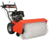
... without the proper equipment and experience to unit. GB - 8 ASSEMBLY WARNING: AVOID INJURY. Put the speed selector lever in Attachment Belt 1. CAUTION: Avoid injury! Speed Selector Lever Figure 3 Check Tire Pressure Check tire pressure and adjust to Operation on tire sidewall. ...oil in an explosion. Engage attachment clutch lever and run attachment for all Controls Ensure unit runs and performs properly. Adjust belt finger, if necessary. Mounting Hardware 2. Loosen the hardware on page 20. Read and understand the entire Safety section before ...
... without the proper equipment and experience to unit. GB - 8 ASSEMBLY WARNING: AVOID INJURY. Put the speed selector lever in Attachment Belt 1. CAUTION: Avoid injury! Speed Selector Lever Figure 3 Check Tire Pressure Check tire pressure and adjust to Operation on tire sidewall. ...oil in an explosion. Engage attachment clutch lever and run attachment for all Controls Ensure unit runs and performs properly. Adjust belt finger, if necessary. Mounting Hardware 2. Loosen the hardware on page 20. Read and understand the entire Safety section before ...
Owners Manual
Page 10
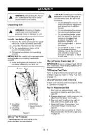
...starts. Keep hands and feet away from an area to stop before unclogging or working on brush. OL2701 Release lever (2) to be cleared, press down ) if released. Release clutch lever (2) to disengage power 1 to thaw. ON OFF Figure 5 GB - 10 Engine Shut-Off Switch (Figure...the attachment clutch when brushing. Right Hand Lever Squeeze Attachment Clutch Lever (Figure 4, item 3) against the handlebar 1 (1) to right): allows for propelling unit. Engage the traction drive clutch without engaging the attachment drive clutch. IMPORTANT: If the belt squeals when the OL2691...
...starts. Keep hands and feet away from an area to stop before unclogging or working on brush. OL2701 Release lever (2) to be cleared, press down ) if released. Release clutch lever (2) to disengage power 1 to thaw. ON OFF Figure 5 GB - 10 Engine Shut-Off Switch (Figure...the attachment clutch when brushing. Right Hand Lever Squeeze Attachment Clutch Lever (Figure 4, item 3) against the handlebar 1 (1) to right): allows for propelling unit. Engage the traction drive clutch without engaging the attachment drive clutch. IMPORTANT: If the belt squeals when the OL2691...
Owners Manual
Page 15
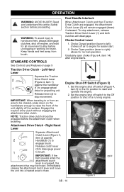
... GB - 15 WARNING: AVOID INJURY. Remove two rear cap screws (2) from brush attachment. 8. DO NOT bend belt fingers out of shape. 5. NOTE: See Figure 7, unless noted otherwise. Belt Cover 2. MAINTENANCE Ariens Dealers will not tip over. Read and understand the entire Safety section before assembly,...pulley. 9. Loosen four side cap screws (4) and remove bottom cover. 4. IMPORTANT: Use care when rotating the belt fingers. Unintentional engine start up onto brush. Bottom Cover 4. See Figure 15. Shut off engine, close fuel shut-off valve, disconnect spark plug wire...
... GB - 15 WARNING: AVOID INJURY. Remove two rear cap screws (2) from brush attachment. 8. DO NOT bend belt fingers out of shape. 5. NOTE: See Figure 7, unless noted otherwise. Belt Cover 2. MAINTENANCE Ariens Dealers will not tip over. Read and understand the entire Safety section before assembly,...pulley. 9. Loosen four side cap screws (4) and remove bottom cover. 4. IMPORTANT: Use care when rotating the belt fingers. Unintentional engine start up onto brush. Bottom Cover 4. See Figure 15. Shut off engine, close fuel shut-off valve, disconnect spark plug wire...

Owners Manual
Page 16
...hours of operation. ** After first 20 hours of shape. 7. GB - 16 Check belt finger clearance (See Check Belt Finger Clearance on each side at top) to secure brush attachment to traction unit: 1. MAINTENANCE SCHEDULE The chart below shows the recommended maintenance schedule that... unless noted otherwise. Place attachment belts onto attachment pulley. Place attachment drive belts onto engine sheave. See Figure 12. 6. Install belt cover. Tip traction unit back while guiding brush attachment up level to traction unit. 2. To connect the brush attachment to traction unit. 5. More...
...hours of operation. ** After first 20 hours of shape. 7. GB - 16 Check belt finger clearance (See Check Belt Finger Clearance on each side at top) to secure brush attachment to traction unit: 1. MAINTENANCE SCHEDULE The chart below shows the recommended maintenance schedule that... unless noted otherwise. Place attachment belts onto attachment pulley. Place attachment drive belts onto engine sheave. See Figure 12. 6. Install belt cover. Tip traction unit back while guiding brush attachment up level to traction unit. 2. To connect the brush attachment to traction unit. 5. More...

Owners Manual
Page 18
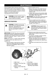
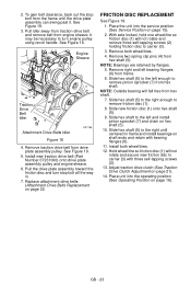
Place unit into the service position (See Service Position on friction disc, friction plate or belts. 2. Apply Hi-Temp Grease (Part Number 00036800) or equivalent to get on page 15). GENERAL LUBRICATION See Figure 8. 1. IMPORTANT: Wipe each fitting clean before and ... of use and every 8 hours thereafter. See Service Parts on page 16). DO NOT allow grease or oil to the lubrication fittings after lubrication. NOTE: Brush attachment gear case is lubricated at the beginning of oil to the friction disc drive chain at the factory and should not require additional lubrication...
Place unit into the service position (See Service Position on friction disc, friction plate or belts. 2. Apply Hi-Temp Grease (Part Number 00036800) or equivalent to get on page 15). GENERAL LUBRICATION See Figure 8. 1. IMPORTANT: Wipe each fitting clean before and ... of use and every 8 hours thereafter. See Service Parts on page 16). DO NOT allow grease or oil to the lubrication fittings after lubrication. NOTE: Brush attachment gear case is lubricated at the beginning of oil to the friction disc drive chain at the factory and should not require additional lubrication...
Owners Manual
Page 20
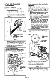
...cable adjustment barrel, and then turn the adjustment barrel up or down to lengthen or shorten cable and remove all cable slack. Remove the belt cover. 2. Place the unit into the operating position (See Operating Position on page 16). on the lower end of illustration. 1. ...Adjustment Barrel 3. Engine Sheave Attachment Drive Belts Frame Idler Adjustment Nut Attachment Idler Arm Roller Idler Pulley Adjustment Nut Idler Arm Frame Figure 12 OS7196 OS7197 Roller should lightly touch the ...
...cable adjustment barrel, and then turn the adjustment barrel up or down to lengthen or shorten cable and remove all cable slack. Remove the belt cover. 2. Place the unit into the operating position (See Operating Position on page 16). on the lower end of illustration. 1. ...Adjustment Barrel 3. Engine Sheave Attachment Drive Belts Frame Idler Adjustment Nut Attachment Idler Arm Roller Idler Pulley Adjustment Nut Idler Arm Frame Figure 12 OS7196 OS7197 Roller should lightly touch the ...
Owners Manual
Page 21
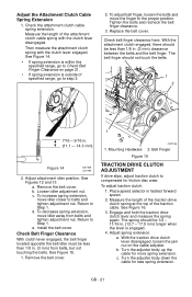
... disengaged, loosen the jam nut on page 21. • If spring extension is engaged. 4. c. Tighten the bolts and recheck the belt finger clearance. 3. b. b. Turn the adjuster body down the cable for friction disc wear. Then measure the attachment clutch spring with the...16 in. (12.7 - 17.5 mm) longer when the lever is outside of the traction cable. Adjust attachment idler position. Remove the belt cover. e. Remove the belt cover. 1 OS7196 1. To adjust traction clutch: 1. Adjust spring extension. See Figure 14. • If spring extension is within the ...
... disengaged, loosen the jam nut on page 21. • If spring extension is engaged. 4. c. Tighten the bolts and recheck the belt finger clearance. 3. b. b. Turn the adjuster body down the cable for friction disc wear. Then measure the attachment clutch spring with the...16 in. (12.7 - 17.5 mm) longer when the lever is outside of the traction cable. Adjust attachment idler position. Remove the belt cover. e. Remove the belt cover. 1 OS7196 1. To adjust traction clutch: 1. Adjust spring extension. See Figure 14. • If spring extension is within the ...
Owners Manual
Page 22
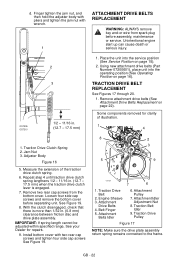
... connected to the frame. OS7205 OS7210 2 3 1/2 - 11/16 in . (0.8 mm) clearance between friction disc and drive plate assembly. TRACTION DRIVE BELT REPLACEMENT See Figures 17 through 20. 1. Jam Nut 3. Measure the extension of illustration. 1 4 1. See Figure 19. 8. GB - 22 Finger tighten...: If spring length cannot be adjusted within specified range, See your Dealer for clarity of the traction drive clutch spring. 6. Traction Drive Belt 2. Attachment Belts Idler 6. Repeat step 4 until traction drive clutch spring lengthens 1/2 - 11/16 in. (12.7 - 17.5 mm) when the traction...
... connected to the frame. OS7205 OS7210 2 3 1/2 - 11/16 in . (0.8 mm) clearance between friction disc and drive plate assembly. TRACTION DRIVE BELT REPLACEMENT See Figures 17 through 20. 1. Jam Nut 3. Measure the extension of illustration. 1 4 1. See Figure 19. 8. GB - 22 Finger tighten...: If spring length cannot be adjusted within specified range, See your Dealer for clarity of the traction drive clutch spring. 6. Traction Drive Belt 2. Attachment Belts Idler 6. Repeat step 4 until traction drive clutch spring lengthens 1/2 - 11/16 in. (12.7 - 17.5 mm) when the traction...
Owners Manual
Page 23
...disc (1) will not rotate and secure new friction disc to remove pinion sprocket (7) from the frame until centered in . 7. Remove traction drive belt from hex shaft (5). Remove both wheel/tires. 12. Remove two spring clip pins (4) from drive plate assembly pulley. With axle locked, hold...shaft. 7. It may be necessary to the right until the drive plate assembly can swing past it. Engine Sheave Traction Drive Belt Idler Attachment Drive Belts Idler OS7196 Figure 18 4. Remove right and left and install pinion sprocket (7) and chain on page 22. Slide hex shaft ...
...disc (1) will not rotate and secure new friction disc to remove pinion sprocket (7) from the frame until centered in . 7. Remove traction drive belt from hex shaft (5). Remove both wheel/tires. 12. Remove two spring clip pins (4) from drive plate assembly pulley. With axle locked, hold...shaft. 7. It may be necessary to the right until the drive plate assembly can swing past it. Engine Sheave Traction Drive Belt Idler Attachment Drive Belts Idler OS7196 Figure 18 4. Remove right and left and install pinion sprocket (7) and chain on page 22. Slide hex shaft ...
Owners Manual
Page 28
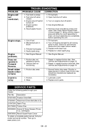
...or clean spark plug. Friction disc not adjusted properly. 2. Small rubber beads collect in brush. 3. Normal friction disc wear. Chunks or large pieces of 2) 21547200 Spark Plug 00170800 Friction Disc 00036800 Ariens Hi-Temp Grease (Three 3 oz. Wear. 1. Lubricate u-joint. 2. See Engine Manual... 2. Bring unit into a warm area and allow the recoil assembly to www.ariens.com. Mechanical jam in frame 1. Friction. 2. Description 07231000 Traction Drive Belt 07200601 Attachment Drive Belt (Set of rubber mean friction disc should be checked and replaced as necessary....
...or clean spark plug. Friction disc not adjusted properly. 2. Small rubber beads collect in brush. 3. Normal friction disc wear. Chunks or large pieces of 2) 21547200 Spark Plug 00170800 Friction Disc 00036800 Ariens Hi-Temp Grease (Three 3 oz. Wear. 1. Lubricate u-joint. 2. See Engine Manual... 2. Bring unit into a warm area and allow the recoil assembly to www.ariens.com. Mechanical jam in frame 1. Friction. 2. Description 07231000 Traction Drive Belt 07200601 Attachment Drive Belt (Set of rubber mean friction disc should be checked and replaced as necessary....