Owners Manual
Page 2
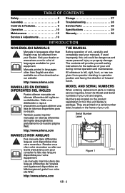
... your dealer or www.ariens.com for the safe use of your manuals. MODEL AND SERIAL NUMBERS When ordering replacement parts or making service inquiries, know the Model and Serial numbers of unit, carefully and completely read your unit during normal operation and maintenance. TABLE OF CONTENTS Safety 4 Assembly 8 Controls & Features 9 Operation 10 Maintenance 15 Service & Adjustments 19 Storage 27 Troubleshooting 28 Service Parts 28 Specifications 29 Warranty 30 INTRODUCTION NON-ENGLISH MANUALS Manuals in languages other...
... your dealer or www.ariens.com for the safe use of your manuals. MODEL AND SERIAL NUMBERS When ordering replacement parts or making service inquiries, know the Model and Serial numbers of unit, carefully and completely read your unit during normal operation and maintenance. TABLE OF CONTENTS Safety 4 Assembly 8 Controls & Features 9 Operation 10 Maintenance 15 Service & Adjustments 19 Storage 27 Troubleshooting 28 Service Parts 28 Specifications 29 Warranty 30 INTRODUCTION NON-ENGLISH MANUALS Manuals in languages other...
Owners Manual
Page 3
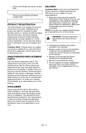
... an Ariens authorized replacement part may adversely affect the performance, durability, or safety of purchase. Some illustrations may void the warranty. Read and understand all assembly has been properly completed. WARNING: Improper assembly or adjustments can cause serious injury. 2. Review control functions and operation of any time without complete assembly and instruction by your retailer, it is returned. • Record Unit Model and Serial number here...
... an Ariens authorized replacement part may adversely affect the performance, durability, or safety of purchase. Some illustrations may void the warranty. Read and understand all assembly has been properly completed. WARNING: Improper assembly or adjustments can cause serious injury. 2. Review control functions and operation of any time without complete assembly and instruction by your retailer, it is returned. • Record Unit Model and Serial number here...
Owners Manual
Page 5
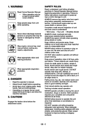
.... DANGER! • Read the operator's manual. • Adjust brush height before operating. • Avoid injury from spark plug before assembly, maintenance or service. Unintentional engine start up can cause injury. DO NOT allow children to dig in Owner/Operator Manual before operation. Check for hidden hazards. DO NOT operate unit without proper training. SAFETY RULES Read, understand, and follow instructions could cause the brush to operate or play on irregular terrain...
.... DANGER! • Read the operator's manual. • Adjust brush height before operating. • Avoid injury from spark plug before assembly, maintenance or service. Unintentional engine start up can cause injury. DO NOT allow children to dig in Owner/Operator Manual before operation. Check for hidden hazards. DO NOT operate unit without proper training. SAFETY RULES Read, understand, and follow instructions could cause the brush to operate or play on irregular terrain...

Owners Manual
Page 6
... good ventilation. Before starting units equipped with electric starter. Use only approved extension cords and receptacles when starting engine, disengage control(s). DO NOT connect electric starter cord to cool before leaving unit. Before cleaning, removing clogs or making any moving parts to maintain, adjust or service. ALWAYS shut off body parts. NEVER secure from all instructions in use . DO NOT transport machine while engine is irregular brush can drive machine rearward. DO...
... good ventilation. Before starting units equipped with electric starter. Use only approved extension cords and receptacles when starting engine, disengage control(s). DO NOT connect electric starter cord to cool before leaving unit. Before cleaning, removing clogs or making any moving parts to maintain, adjust or service. ALWAYS shut off body parts. NEVER secure from all instructions in use . DO NOT transport machine while engine is irregular brush can drive machine rearward. DO...

Owners Manual
Page 7
... fuel container. DO NOT use a nozzle lockopen device. Before separating brush attachment from the truck or trailer and refuel it is used, must be maintained in any unimproved, forest-covered or brush covered land unless exhaust system is complete. Adjust brush height before storing in safe operating condition. Always place containers on clothing, change engine governor settings or over during maintenance. Maintain or replace safety and instruction...
... fuel container. DO NOT use a nozzle lockopen device. Before separating brush attachment from the truck or trailer and refuel it is used, must be maintained in any unimproved, forest-covered or brush covered land unless exhaust system is complete. Adjust brush height before storing in safe operating condition. Always place containers on clothing, change engine governor settings or over during maintenance. Maintain or replace safety and instruction...
Owners Manual
Page 8
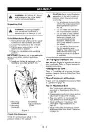
... rim parts is shipped with 5W-30 oil in personal injury or damage to Check Attachment Idler Arm Roller Clearance on tire sidewall. Start unit in an explosion. Mounting Hardware 2. Speed Selector Lever Figure 3 Check Tire Pressure Check tire pressure and adjust to stop, and remove spark plug wire. 4. Stop unit, wait for about 15 minutes. 3. Adjust belt finger, if necessary. GB - 8 Welding can cause an increase in air pressure...
... rim parts is shipped with 5W-30 oil in personal injury or damage to Check Attachment Idler Arm Roller Clearance on tire sidewall. Start unit in an explosion. Mounting Hardware 2. Speed Selector Lever Figure 3 Check Tire Pressure Check tire pressure and adjust to stop, and remove spark plug wire. 4. Stop unit, wait for about 15 minutes. 3. Adjust belt finger, if necessary. GB - 8 Welding can cause an increase in air pressure...
Owners Manual
Page 9
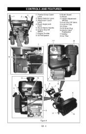
Recoil Starter Handle 15.Oil Drain Plug 6. Brush Guard 10.Brush 2. Brush Angle Lock 13.Fuel Fill Cap Lever 14.Choke 5. Engine Throttle 17.Muffler 8. CONTROLS AND FEATURES 1 3 2 1. Engine Shut Off 4 Switch 16.Electric Start Pushbutton 7. Traction Drive Clutch Lever 9. Oil Fill/Dipstick 18.Air Filter 17 18 7 14 12 13 6 5 16 8 32 15 1 9 4 8 11 10 15 Figure 4 GB - 9 Attachment Clutch Wheels Lever 12.Fuel Shut Off Valve 4. Speed Selector Lever 11.Height Adjustment 3.
Recoil Starter Handle 15.Oil Drain Plug 6. Brush Guard 10.Brush 2. Brush Angle Lock 13.Fuel Fill Cap Lever 14.Choke 5. Engine Throttle 17.Muffler 8. CONTROLS AND FEATURES 1 3 2 1. Engine Shut Off 4 Switch 16.Electric Start Pushbutton 7. Traction Drive Clutch Lever 9. Oil Fill/Dipstick 18.Air Filter 17 18 7 14 12 13 6 5 16 8 32 15 1 9 4 8 11 10 15 Figure 4 GB - 9 Attachment Clutch Wheels Lever 12.Fuel Shut Off Valve 4. Speed Selector Lever 11.Height Adjustment 3.
Owners Manual
Page 11
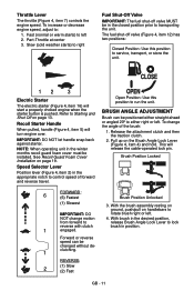
... fuel shut-off valve MUST be installed. Refer to Starting and Shut Off on handlebars to control speed of the brush: 1. Speed Selector Lever Position lever (Figure 4, item 2) in position. 1 engaged. Open Position: Use this position to either right or left 2. BRUSH ANGLE ADJUSTMENT Brush can be positioned either straight ahead or angled 20º to service, transport, or store the unit. 12 3 Electric Starter The electric starter (Figure 4, item 16) will start a properly choked engine when...
... fuel shut-off valve MUST be installed. Refer to Starting and Shut Off on handlebars to control speed of the brush: 1. Speed Selector Lever Position lever (Figure 4, item 2) in position. 1 engaged. Open Position: Use this position to either right or left 2. BRUSH ANGLE ADJUSTMENT Brush can be positioned either straight ahead or angled 20º to service, transport, or store the unit. 12 3 Electric Starter The electric starter (Figure 4, item 16) will start a properly choked engine when...
Owners Manual
Page 12
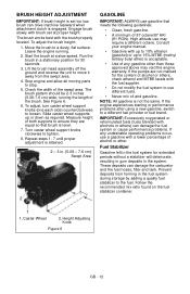
... adjustment is attained. 2 - 3 in the fuel system for 30 seconds. 3. Turn caster wheel support knobs clockwise to loosen. Leave the engine running the length of the swept area. High altitude use different fuels. • Never mix oil and gasoline. To adjust the brush height: 1. The brush pattern should be 2-3 inches (5.08-7.6 cm) wide, running . 2. Engage brush slowly with the brush properly leveled. BRUSH HEIGHT ADJUSTMENT IMPORTANT: If brush height is set at a slow speed. To adjust, turn caster wheel support knobs...
... adjustment is attained. 2 - 3 in the fuel system for 30 seconds. 3. Turn caster wheel support knobs clockwise to loosen. Leave the engine running the length of the swept area. High altitude use different fuels. • Never mix oil and gasoline. To adjust the brush height: 1. The brush pattern should be 2-3 inches (5.08-7.6 cm) wide, running . 2. Engage brush slowly with the brush properly leveled. BRUSH HEIGHT ADJUSTMENT IMPORTANT: If brush height is set at a slow speed. To adjust, turn caster wheel support knobs...
Owners Manual
Page 13
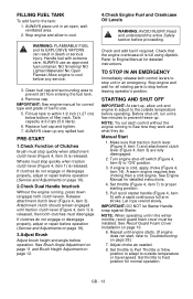
... detailed instructions. 4. Manual Start 1. Pull recoil starter handle (Figure 4, item 5) with extreme care. Wheels must stop quickly when attachment clutch lever (Figure 4, item 3) is released, then both control levers to proper starting position. 5. Allow engine to cool before proceeding. Replace fuel cap and tighten. 7. See Brush Angle Adjustment on page 11 and Brush Height Adjustment on page 19. 6. See Recoil Guard Foam Cover Installation on page 12. 4.Check Engine Fuel and Crankcase Oil Levels WARNING: AVOID INJURY. Check that traction clutch lever (Figure...
... detailed instructions. 4. Manual Start 1. Pull recoil starter handle (Figure 4, item 5) with extreme care. Wheels must stop quickly when attachment clutch lever (Figure 4, item 3) is released, then both control levers to proper starting position. 5. Allow engine to cool before proceeding. Replace fuel cap and tighten. 7. See Brush Angle Adjustment on page 11 and Brush Height Adjustment on page 19. 6. See Recoil Guard Foam Cover Installation on page 12. 4.Check Engine Fuel and Crankcase Oil Levels WARNING: AVOID INJURY. Check that traction clutch lever (Figure...
Owners Manual
Page 14
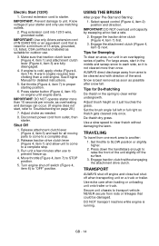
... speed control (Figure 4, item 2) position and direction. Tips for detailed instructions. 5. DO NOT transport machine while engine is not cleared more than a cold engine. Electric Start (120V) 1. Set throttle (Figure 4, item 7) to SLOW position or slightly higher. 2. Press starter button (Figure 4, item 16) on a truck or trailer. Snow is cold, apply choke (Figure 4, item 14). Set throttle to proper starting position. 6. Engage traction clutch without damaging the lawn. See Engine Manual for...
... speed control (Figure 4, item 2) position and direction. Tips for detailed instructions. 5. DO NOT transport machine while engine is not cleared more than a cold engine. Electric Start (120V) 1. Set throttle (Figure 4, item 7) to SLOW position or slightly higher. 2. Press starter button (Figure 4, item 16) on a truck or trailer. Snow is cold, apply choke (Figure 4, item 14). Set throttle to proper starting position. 6. Engage traction clutch without damaging the lawn. See Engine Manual for...
Owners Manual
Page 15
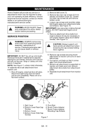
.... 5. Shut off engine, close fuel shut-off valve, disconnect spark plug wire and allow unit to keep your unit operating at top). 7. Read and understand the entire Safety section before assembly, maintenance or service. Remove belt cover (1). 3. Remove two rear cap screws (2) from traction unit: 1. Ensure unit is supported on a flat level surface. 6. Bottom Cover 4. SERVICE POSITION WARNING: ALWAYS remove key and/or wire from attachment pulley. 9. Loosen four side cap screws (4) and remove bottom cover. 4. Remove attachment drive belts from traction unit...
.... 5. Shut off engine, close fuel shut-off valve, disconnect spark plug wire and allow unit to keep your unit operating at top). 7. Read and understand the entire Safety section before assembly, maintenance or service. Remove belt cover (1). 3. Remove two rear cap screws (2) from traction unit: 1. Ensure unit is supported on a flat level surface. 6. Bottom Cover 4. SERVICE POSITION WARNING: ALWAYS remove key and/or wire from attachment pulley. 9. Loosen four side cap screws (4) and remove bottom cover. 4. Remove attachment drive belts from traction unit...

Owners Manual
Page 16
... belt fingers. Place attachment belts onto attachment pulley. IMPORTANT: DO NOT bend belt fingers out of operation. More frequent service may be performed on page 21). GB - 16 MAINTENANCE SCHEDULE Service Performed Each Use Daily (8 hrs.) Every 25 hours Yearly or 100 hrs Check Dual Handle • Interlock Check Fasteners • Check Clutch Operation • Clean Engine • Clean Recoil Guard Foam • Cover Check Engine Oil *• General Lubrication • Check Clutch Spring *• Adjustments Check Tire Pressure • Change Engine Oil...
... belt fingers. Place attachment belts onto attachment pulley. IMPORTANT: DO NOT bend belt fingers out of operation. More frequent service may be performed on page 21). GB - 16 MAINTENANCE SCHEDULE Service Performed Each Use Daily (8 hrs.) Every 25 hours Yearly or 100 hrs Check Dual Handle • Interlock Check Fasteners • Check Clutch Operation • Clean Engine • Clean Recoil Guard Foam • Cover Check Engine Oil *• General Lubrication • Check Clutch Spring *• Adjustments Check Tire Pressure • Change Engine Oil...
Owners Manual
Page 17
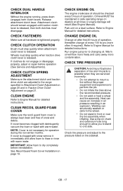
...! CHECK CLUTCH OPERATION Brush must stop quickly when attachment clutch lever is clogged with warm water. CHECK CLUTCH SPRING ADJUSTMENT Make sure the attachment clutch and traction drive clutch are serviced incorrectly: • Do not attempt to mount a tire without the proper equipment and experience to the pressure listed on page 21. See Recoil Guard Foam Cover Installation on a level surface. Use a clip-on dipstick at all hardware is always kept clean and free of operation...
...! CHECK CLUTCH OPERATION Brush must stop quickly when attachment clutch lever is clogged with warm water. CHECK CLUTCH SPRING ADJUSTMENT Make sure the attachment clutch and traction drive clutch are serviced incorrectly: • Do not attempt to mount a tire without the proper equipment and experience to the pressure listed on page 21. See Recoil Guard Foam Cover Installation on a level surface. Use a clip-on dipstick at all hardware is always kept clean and free of operation...
Owners Manual
Page 21
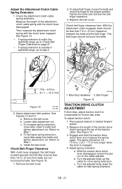
... to belts and tighten adjustment nut. Check belt finger clearance here. See Figures 12 and 13. Remove the belt cover. b. To increase spring extension, move idler away from belts, but not touching the belts. To decrease spring extension, move idler closer to the proper position. Install the belt cover. Check the attachment clutch cable spring extension. Adjust attachment idler position. Return to Step 1. Return to Step 1. Check Belt Finger Clearance With clutch lever engaged, the belt finger located opposite the belt...
... to belts and tighten adjustment nut. Check belt finger clearance here. See Figures 12 and 13. Remove the belt cover. b. To increase spring extension, move idler away from belts, but not touching the belts. To decrease spring extension, move idler closer to the proper position. Install the belt cover. Check the attachment clutch cable spring extension. Adjust attachment idler position. Return to Step 1. Return to Step 1. Check Belt Finger Clearance With clutch lever engaged, the belt finger located opposite the belt...
Owners Manual
Page 22
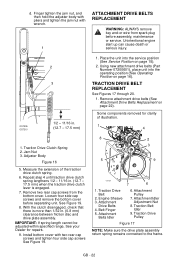
... Attachment Drive Belts Replacement on page 15). 2. Some components removed for repairs. 9. Measure the extension of illustration. 1 4 1. Using new attachment drive belts (Part Number 07200601), place unit into the service position (See Service Position on page 22). Adjuster Body Figure 16 5. Remove two rear cap screws from spark plug before separating unit. Traction Drive Belt 2. d. Jam Nut 3. See Figure 19. 8. IMPORTANT: If spring length cannot be adjusted within specified range, See your Dealer for clarity of the traction drive clutch spring...
... Attachment Drive Belts Replacement on page 15). 2. Some components removed for repairs. 9. Measure the extension of illustration. 1 4 1. Using new attachment drive belts (Part Number 07200601), place unit into the service position (See Service Position on page 22). Adjuster Body Figure 16 5. Remove two rear cap screws from spark plug before separating unit. Traction Drive Belt 2. d. Jam Nut 3. See Figure 19. 8. IMPORTANT: If spring length cannot be adjusted within specified range, See your Dealer for clarity of the traction drive clutch spring...
Owners Manual
Page 23
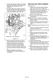
... Service Position on page 22. FRICTION DISC REPLACEMENT See Figure 19. 1. NOTE: Outside bearing will not rotate and secure new friction disc to remove pinion sprocket (7) from hex shaft. 7. Hold wheel/tire so friction disc (1) will fall free from hex shaft. NOTE: Bearings are retained by flanges. 5. Remove two spring clip pins (4) from frame. 6. Install both wheel/tires. 4. GB - 23 Install new traction drive belt (Part Number 07231000) onto drive plate assembly pulley...
... Service Position on page 22. FRICTION DISC REPLACEMENT See Figure 19. 1. NOTE: Outside bearing will not rotate and secure new friction disc to remove pinion sprocket (7) from hex shaft. 7. Hold wheel/tire so friction disc (1) will fall free from hex shaft. NOTE: Bearings are retained by flanges. 5. Remove two spring clip pins (4) from frame. 6. Install both wheel/tires. 4. GB - 23 Install new traction drive belt (Part Number 07231000) onto drive plate assembly pulley...
Owners Manual
Page 28
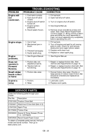
...Traction belt not functioning. 1. SERVICE PARTS Order the following parts through your model and serial number. Friction disc wear. 1. Fill fuel tank. 2. Open fuel shut-off engine and wait for and remove obstruction and repair before operating the unit. Lubricate u-joint. 2. Repair or replace friction disc. Turn off valve. 3. See Engine Manual. Turn on page 17. Remove snow and debris screen and clean. See Engine Manual. 1. TROUBLESHOOTING PROBLEM PROBABLE CAUSE CORRECTION Engine will not crank/start. 1. See Clean Recoil Guard Foam Cover on engine...
...Traction belt not functioning. 1. SERVICE PARTS Order the following parts through your model and serial number. Friction disc wear. 1. Fill fuel tank. 2. Open fuel shut-off engine and wait for and remove obstruction and repair before operating the unit. Lubricate u-joint. 2. Repair or replace friction disc. Turn off valve. 3. See Engine Manual. Turn on page 17. Remove snow and debris screen and clean. See Engine Manual. 1. TROUBLESHOOTING PROBLEM PROBABLE CAUSE CORRECTION Engine will not crank/start. 1. See Clean Recoil Guard Foam Cover on engine...
Owners Manual
Page 30
..., Tillers, String Trimmers, Log Splitters, Edgers and Power Brushes Ariens Company (Ariens) warrants to the Ariens Company, or register the unit online at the time of sale. Two-Year Limited Warranty on AMP™ Series Battery Packs and Subassemblies The battery pack and/or battery subassemblies on AMP series electric mowers is put to personal use around a household or residence. One-Year Limited Warranty on Service Parts and Accessories Genuine Ariens or Gravely brand service parts...
..., Tillers, String Trimmers, Log Splitters, Edgers and Power Brushes Ariens Company (Ariens) warrants to the Ariens Company, or register the unit online at the time of sale. Two-Year Limited Warranty on AMP™ Series Battery Packs and Subassemblies The battery pack and/or battery subassemblies on AMP series electric mowers is put to personal use around a household or residence. One-Year Limited Warranty on Service Parts and Accessories Genuine Ariens or Gravely brand service parts...
Owners Manual
Page 31
..., spark plugs, oil, oil filters, air filters, fuel filters, brake linings, brake arms, brake shoes, runners, scraper blades, shear bolts, mower blades, mower vanes, tines, brushes, headlights, light bulbs, knives, cutters. • Any misuse, alteration, improper assembly, improper adjustment, neglect, or accident which vary from time to 12 months after date of its products. Nothing contained in workmanship, and repair or replacement of any other countries, contact place of fitness for warranty information. DISCLAIMER OF FURTHER WARRANTY Ariens Company...
..., spark plugs, oil, oil filters, air filters, fuel filters, brake linings, brake arms, brake shoes, runners, scraper blades, shear bolts, mower blades, mower vanes, tines, brushes, headlights, light bulbs, knives, cutters. • Any misuse, alteration, improper assembly, improper adjustment, neglect, or accident which vary from time to 12 months after date of its products. Nothing contained in workmanship, and repair or replacement of any other countries, contact place of fitness for warranty information. DISCLAIMER OF FURTHER WARRANTY Ariens Company...


