Owners Manual
Page 2
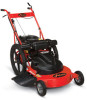
... also printed on a serial number label, located on our website: http://www.ariens.com MANUALES EN IDIOMAS DIFERENTES DEL INGLES Puede obtener manuales en idiomas diferentes del inglés en su distribuidor. Engine Serial Number Label Unit Serial Number Label Figure 1 GB - 2 © ...Copyright 2012 Ariens Company TABLE OF CONTENTS Safety 4 Assembly 9 Controls and Features 14 Operation 15 Maintenance 19 ...
... also printed on a serial number label, located on our website: http://www.ariens.com MANUALES EN IDIOMAS DIFERENTES DEL INGLES Puede obtener manuales en idiomas diferentes del inglés en su distribuidor. Engine Serial Number Label Unit Serial Number Label Figure 1 GB - 2 © ...Copyright 2012 Ariens Company TABLE OF CONTENTS Safety 4 Assembly 9 Controls and Features 14 Operation 15 Maintenance 19 ...

Owners Manual
Page 3
... thoroughly read and understand them. • Record Unit Model and Serial numbers here: • Record Engine Model & Serial numbers here: PRODUCT REGISTRATION The Ariens dealer must register the product at the time of unauthorized replacement parts. DEALER DELIVERY CAUTION: DO NOT... affect the performance, durability, or safety of unit. DISCLAIMER Ariens reserves the right to discontinue, make changes to change oil in this manual may occur. Give customer Owner/Operator, Parts, and Engine manuals. Dealer should advise customer of operation. 5. Advise customer...
... thoroughly read and understand them. • Record Unit Model and Serial numbers here: • Record Engine Model & Serial numbers here: PRODUCT REGISTRATION The Ariens dealer must register the product at the time of unauthorized replacement parts. DEALER DELIVERY CAUTION: DO NOT... affect the performance, durability, or safety of unit. DISCLAIMER Ariens reserves the right to discontinue, make changes to change oil in this manual may occur. Give customer Owner/Operator, Parts, and Engine manuals. Dealer should advise customer of operation. 5. Advise customer...

Owners Manual
Page 4
... objects. Never assume that children will use the unit, ALWAYS provide this manual and any needed safety training before leaving operator's position. Stop unit and engine and allow moving parts to point out important safety precautions. It may also be used on decals and in serious injury or death. If anyone...
... objects. Never assume that children will use the unit, ALWAYS provide this manual and any needed safety training before leaving operator's position. Stop unit and engine and allow moving parts to point out important safety precautions. It may also be used on decals and in serious injury or death. If anyone...

Owners Manual
Page 5
.... DANGER! OL1801 Keep children and others away from spark plug before assembly. OL4370 Never direct discharge toward other than original purchaser; Failure to unit. Unintentional engine start up can cause injury. Figure 2 1. Thrown objects can cause death or serious injury. OL3030 3. GB - 5 Do not allow operation of machine by untrained personnel...
.... DANGER! OL1801 Keep children and others away from spark plug before assembly. OL4370 Never direct discharge toward other than original purchaser; Failure to unit. Unintentional engine start up can cause injury. Figure 2 1. Thrown objects can cause death or serious injury. OL3030 3. GB - 5 Do not allow operation of machine by untrained personnel...
Owners Manual
Page 6
... feature frequently. NEVER allow blade to stop before servicing. Fumes from engine exhaust can hide obstacles. DO NOT run . Wear sturdy footwear, gloves, a hard hat and safety goggles or safety glasses with Ariens original equipment replacement parts for safety. NEVER operate mower barefoot or when... wearing open sandals or canvas shoes. DO NOT touch hot parts. DO NOT attempt to make cutting height wheel adjustments while the engine is running. DO NOT ...
... feature frequently. NEVER allow blade to stop before servicing. Fumes from engine exhaust can hide obstacles. DO NOT run . Wear sturdy footwear, gloves, a hard hat and safety goggles or safety glasses with Ariens original equipment replacement parts for safety. NEVER operate mower barefoot or when... wearing open sandals or canvas shoes. DO NOT touch hot parts. DO NOT attempt to make cutting height wheel adjustments while the engine is running. DO NOT ...
Owners Manual
Page 7
... for your unit. Check attachments frequently and replace worn or damaged components with an internal combustion engine. CAUTION: DO NOT drop machine when loading or unloading or damage to service. See your Ariens Dealer or engine manufacturer's service center. If this feature fails to operate, disconnect spark plug wire and repair before extended...
... for your unit. Check attachments frequently and replace worn or damaged components with an internal combustion engine. CAUTION: DO NOT drop machine when loading or unloading or damage to service. See your Ariens Dealer or engine manufacturer's service center. If this feature fails to operate, disconnect spark plug wire and repair before extended...
Owners Manual
Page 8
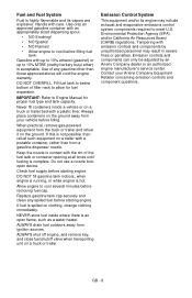
...trailer. Handle with emission controls and components by an Ariens Company dealer or an authorized engine manufacturer's service center. When practical, remove gas-powered equipment from your Ariens Company Equipment Retailer concerning emission controls and component questions. ...Check fuel supply before starting engine. Allow engine to cool several minutes before filling fuel tank. If this...
...trailer. Handle with emission controls and components by an Ariens Company dealer or an authorized engine manufacturer's service center. When practical, remove gas-powered equipment from your Ariens Company Equipment Retailer concerning emission controls and component questions. ...Check fuel supply before starting engine. Allow engine to cool several minutes before filling fuel tank. If this...

Owners Manual
Page 10
Apply pressure against rear wheels. Slide cable wire through slot in place. Press cable clip into the engine flywheel brake actuation arm through bellcrank stud to the front of Engine) GB - 10 Figure 7 Install a flat washer, the actuation link and a second flat washer on the bellcrank...to secure actuation link. Flat Washer Bellcrank Stud Hairpin OPC Cable End Cable Clip Slot Oil Fill Engine Flywheel Brake Actuation Arm Cable Mounting Bracket Figure 6 (Front of the engine. 1. Install hairpin through the bottom side. 2. Connect OPC cable end to install the wheel ...
Apply pressure against rear wheels. Slide cable wire through slot in place. Press cable clip into the engine flywheel brake actuation arm through bellcrank stud to the front of Engine) GB - 10 Figure 7 Install a flat washer, the actuation link and a second flat washer on the bellcrank...to secure actuation link. Flat Washer Bellcrank Stud Hairpin OPC Cable End Cable Clip Slot Oil Fill Engine Flywheel Brake Actuation Arm Cable Mounting Bracket Figure 6 (Front of the engine. 1. Install hairpin through the bottom side. 2. Connect OPC cable end to install the wheel ...

Owners Manual
Page 11
...tighten cap screw. Position throttle control (on handlebar) all the way forward (down between handlebar and wheel drive actuation link. 3. Push engine throttle lever fully forward until horizontal and position over cable and attach to secure the OPC and throttle cables. See Figure 9. •... 9. Loop end of cable ties. The throttle lever may also be positioned against its stop . Tighten the slotted hex cap screw to engine throttle lever. 4. Throttle Cable Cable Clamp Throttle Lever Throttle Cable 2 Throttle Lever Cable Clamp Cap Screw 3 Cap Screw Handlebar 1 Wheel ...
...tighten cap screw. Position throttle control (on handlebar) all the way forward (down between handlebar and wheel drive actuation link. 3. Push engine throttle lever fully forward until horizontal and position over cable and attach to secure the OPC and throttle cables. See Figure 9. •... 9. Loop end of cable ties. The throttle lever may also be positioned against its stop . Tighten the slotted hex cap screw to engine throttle lever. 4. Throttle Cable Cable Clamp Throttle Lever Throttle Cable 2 Throttle Lever Cable Clamp Cap Screw 3 Cap Screw Handlebar 1 Wheel ...
Owners Manual
Page 13
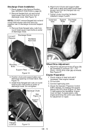
...Figure 13 GB - 13 Discharge Chute See Figure 14 Support Plate Figure 14 Wheel Drive Adjustment 1. Check engine oil level and add if necessary. Connect spark plug wire. 4. If engine starts, stop engine and bring the unit to achieve 1/8" - 1/4" (3mm - 6mm) drive roller gap at center of...and support plate with hole in mower deck. Install three flanged lock nuts on page 20. 2. Discharge Chute Installation 1. Engine Preparation 1. Try starting the engine without the OPC lever (Figure 15, Item 1) held against the handlebar. Remove flanged lock nut and round head square ...
...Figure 13 GB - 13 Discharge Chute See Figure 14 Support Plate Figure 14 Wheel Drive Adjustment 1. Check engine oil level and add if necessary. Connect spark plug wire. 4. If engine starts, stop engine and bring the unit to achieve 1/8" - 1/4" (3mm - 6mm) drive roller gap at center of...and support plate with hole in mower deck. Install three flanged lock nuts on page 20. 2. Discharge Chute Installation 1. Engine Preparation 1. Try starting the engine without the OPC lever (Figure 15, Item 1) held against the handlebar. Remove flanged lock nut and round head square ...

Owners Manual
Page 14
Wheel Drive Control Handlebars 4. Lower Guard 10. Operator Presence (Engine/Blade) Control 2. Muffler GB - 14 Recoil Starter Handle 3. Fuel Tank and Cap 7. Fixed Front Wheels (Standard) 11. 11 10 CONTROLS AND FEATURES 5 4 1 3 2 8 7 6 4 9 13 12 Figure 15 1. Air Filter 6. Discharge Chute 9. Engine Throttle Control 5. Oil Fill/Dipstick 12. Upper (Wheel Drive) Guard 8.
Wheel Drive Control Handlebars 4. Lower Guard 10. Operator Presence (Engine/Blade) Control 2. Muffler GB - 14 Recoil Starter Handle 3. Fuel Tank and Cap 7. Fixed Front Wheels (Standard) 11. 11 10 CONTROLS AND FEATURES 5 4 1 3 2 8 7 6 4 9 13 12 Figure 15 1. Air Filter 6. Discharge Chute 9. Engine Throttle Control 5. Oil Fill/Dipstick 12. Upper (Wheel Drive) Guard 8.

Owners Manual
Page 15
... is released. The drive speed may cause damage or injury. Thrown objects may be manually held against the handlebar to start the engine and blade. Recoil Starter Handle When pulled, recoil starter handle will disengage when this feature frequently. CAUTION: If clog or obstruction .... Releasing the OPC lever grounds engine spark and applies engine flywheel brake, stopping the engine and blade within 3 seconds. Check this lever is preset and cannot be held against the handlebar to engage wheel drive. See Wheel Drive Speed Adjustment on page 24. GB - 15 CAUTION: DO...
... is released. The drive speed may cause damage or injury. Thrown objects may be manually held against the handlebar to start the engine and blade. Recoil Starter Handle When pulled, recoil starter handle will disengage when this feature frequently. CAUTION: If clog or obstruction .... Releasing the OPC lever grounds engine spark and applies engine flywheel brake, stopping the engine and blade within 3 seconds. Check this lever is preset and cannot be held against the handlebar to engage wheel drive. See Wheel Drive Speed Adjustment on page 24. GB - 15 CAUTION: DO...

Owners Manual
Page 16
...area. 4. IMPORTANT: DO NOT let starter handle snap against the handlebar, grasp starter handle and pull rope slowly until engine starts. (If engine does not start engine. Keep mower blades sharp. Mow with rapid continuous full arm stroke to start , see TROUBLESHOOTING on page 36. ... neck to allow to below bottom of the MAINTENANCE SCHEDULE on a level surface that features a temperature-controlled automatic choke. NOTE: Start engine on page 19. 2. Remove cap. See SPECIFICATIONS on page 34.) Shut Off 1. Thoroughly read and understand entire Operator Manual. 3. ALWAYS...
...area. 4. IMPORTANT: DO NOT let starter handle snap against the handlebar, grasp starter handle and pull rope slowly until engine starts. (If engine does not start engine. Keep mower blades sharp. Mow with rapid continuous full arm stroke to start , see TROUBLESHOOTING on page 36. ... neck to allow to below bottom of the MAINTENANCE SCHEDULE on a level surface that features a temperature-controlled automatic choke. NOTE: Start engine on page 19. 2. Remove cap. See SPECIFICATIONS on page 34.) Shut Off 1. Thoroughly read and understand entire Operator Manual. 3. ALWAYS...

Owners Manual
Page 17
Stop engine, wait for all moving parts to stop and hot parts to cool before adjusting height of cut. 5. Place unit on axle bolt. 11. Wheel Figure ... height is against mower frame. Place axles in a series of mounting holes. Raise back of mower to lift rear wheels off engine, wait for moving parts to stop and allow engine to cool. 2. Install wheel/tire assembly on a flat, level surface. 3. Connect spark plug wire to rear wheel height settings. 13. ALWAYS...
Stop engine, wait for all moving parts to stop and hot parts to cool before adjusting height of cut. 5. Place unit on axle bolt. 11. Wheel Figure ... height is against mower frame. Place axles in a series of mounting holes. Raise back of mower to lift rear wheels off engine, wait for moving parts to stop and allow engine to cool. 2. Install wheel/tire assembly on a flat, level surface. 3. Connect spark plug wire to rear wheel height settings. 13. ALWAYS...

Owners Manual
Page 18
... of the standard, fixed front wheels is set the same as rear wheel height for a 2.7" (69mm) cut holes are spaced approximately 0.665" (17mm) apart. Stop engine, wait for higher cut hole. 7. Raise front of Cut Holes GB - 18 The mower is changed by raising or lowering wheels in the four available...
... of the standard, fixed front wheels is set the same as rear wheel height for a 2.7" (69mm) cut holes are spaced approximately 0.665" (17mm) apart. Stop engine, wait for higher cut hole. 7. Raise front of Cut Holes GB - 18 The mower is changed by raising or lowering wheels in the four available...
Owners Manual
Page 19
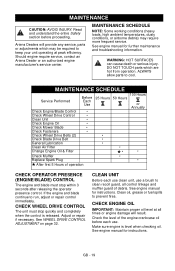
...which are hot from operation. CHECK ENGINE OIL IMPORTANT: Maintain proper oil level at peak efficiency. Should engine require service, contact an Ariens Dealer or an authorized engine manufacturer's service center. Adjust or repair if necessary. See engine manual for further maintenance and troubleshooting ...- 19 Read and understand the entire Safety section before each use clean unit, use . Ariens Dealers will result. See engine manual for instructions. If the engine and blade continue to prevent fires. CHECK WHEEL DRIVE CONTROL The unit must stop quickly and...
...which are hot from operation. CHECK ENGINE OIL IMPORTANT: Maintain proper oil level at peak efficiency. Should engine require service, contact an Ariens Dealer or an authorized engine manufacturer's service center. Adjust or repair if necessary. See engine manual for further maintenance and troubleshooting ...- 19 Read and understand the entire Safety section before each use clean unit, use . Ariens Dealers will result. See engine manual for instructions. If the engine and blade continue to prevent fires. CHECK WHEEL DRIVE CONTROL The unit must stop quickly and...

Owners Manual
Page 20
... amount of material from unit. Blade should fully compress lock washer. Block blade to help prevent fuel spills. Follow steps below to prevent rotation. 3. Stop engine, wait for nicks and dull cutting edges. IMPORTANT: After service is complete and unit is removed. Install Mower Blade NOTE: Ensure blade air lift points...
... amount of material from unit. Blade should fully compress lock washer. Block blade to help prevent fuel spills. Follow steps below to prevent rotation. 3. Stop engine, wait for nicks and dull cutting edges. IMPORTANT: After service is complete and unit is removed. Install Mower Blade NOTE: Ensure blade air lift points...

Owners Manual
Page 21
...GENERAL LUBRICATION Lubricate wheel drive shaft through grease fitting every to a torque of operation. See engine manual for wear and/or damage and replace as necessary. Figure 22 CHANGE ENGINE OIL Change engine crankcase oil after every 50 hours of operation. DO NOT overfill. If either end of dirt... Refer to blade hardware and all fasteners for instructions and proper oil type. See Figure 21. Lightly oil all times or engine damage will result. Air Lift Erosion Figure 20 3. CHECK FASTENERS Check all guards, shields and safety devices. Pay special attention to...
...GENERAL LUBRICATION Lubricate wheel drive shaft through grease fitting every to a torque of operation. See engine manual for wear and/or damage and replace as necessary. Figure 22 CHANGE ENGINE OIL Change engine crankcase oil after every 50 hours of operation. DO NOT overfill. If either end of dirt... Refer to blade hardware and all fasteners for instructions and proper oil type. See Figure 21. Lightly oil all times or engine damage will result. Air Lift Erosion Figure 20 3. CHECK FASTENERS Check all guards, shields and safety devices. Pay special attention to...

Owners Manual
Page 22
... drain from tube. 4. Turn oil filter counterclockwise to Engine Manual for instructions and proper oil type. 9. Refer to remove. See engine manual for debris, cracks, wear, or other damage every 50 hours of operation. Add engine oil. Oil Fill Tube with Cap/Dipstick CHECK MUFFLER ... plug wire terminals can cause sparking. See Figure 23. 5. Remove plastic from oil filter and surrounding area. 2. Place a suitable container below engine oil fill tube and remove cap to allow oil to spark plug. Install new filter and hand tighten securely. 7. Install oil fill cap. ...
... drain from tube. 4. Turn oil filter counterclockwise to Engine Manual for instructions and proper oil type. 9. Refer to remove. See engine manual for debris, cracks, wear, or other damage every 50 hours of operation. Add engine oil. Oil Fill Tube with Cap/Dipstick CHECK MUFFLER ... plug wire terminals can cause sparking. See Figure 23. 5. Remove plastic from oil filter and surrounding area. 2. Place a suitable container below engine oil fill tube and remove cap to allow oil to spark plug. Install new filter and hand tighten securely. 7. Install oil fill cap. ...
Owners Manual
Page 23
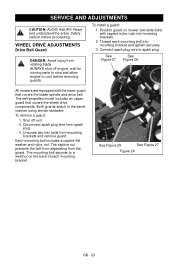
ALWAYS shut off unit. 2. To install a guard: 1. Shut off engine, wait for moving parts to stop and allow engine to cool before proceeding. Each mounting bolt includes a captive flat washer and nyloc nut. Thread each mounting bracket. Connect spark plug wire to a weldnut ... prevents the bolt from separating from mounting brackets and remove guard. Unscrew two hex bolts from the guard. See Figure 25 See Figure 27 Figure 24 GB - 23 Read and understand the entire Safety section before removing guards. Position guard on the back of each mounting bolt into mounting brackets. 2....
ALWAYS shut off unit. 2. To install a guard: 1. Shut off engine, wait for moving parts to stop and allow engine to cool before proceeding. Each mounting bolt includes a captive flat washer and nyloc nut. Thread each mounting bracket. Connect spark plug wire to a weldnut ... prevents the bolt from separating from mounting brackets and remove guard. Unscrew two hex bolts from the guard. See Figure 25 See Figure 27 Figure 24 GB - 23 Read and understand the entire Safety section before removing guards. Position guard on the back of each mounting bolt into mounting brackets. 2....

