
Owners Manual
Page 2
... safe use of your unit during normal operation and maintenance. If the engine manual is included in the literature package that shipped with safety instructions for a replacement manual. They are located on the frame of your unit. TABLE OF CONTENTS SAFETY 4 ASSEMBLY 8 CONTROLS and FEATURES 12 OPERATION 13 MAINTENANCE 20 SERVICE AND ADJUSTMENTS . . . . . 23 STORAGE 33 SERVICE PARTS 33 ACCESSORIES 33 TROUBLESHOOTING 34 SPECIFICATIONS 35 WARRANTY 38 INTRODUCTION NON-ENGLISH MANUALS Manuals...
... safe use of your unit during normal operation and maintenance. If the engine manual is included in the literature package that shipped with safety instructions for a replacement manual. They are located on the frame of your unit. TABLE OF CONTENTS SAFETY 4 ASSEMBLY 8 CONTROLS and FEATURES 12 OPERATION 13 MAINTENANCE 20 SERVICE AND ADJUSTMENTS . . . . . 23 STORAGE 33 SERVICE PARTS 33 ACCESSORIES 33 TROUBLESHOOTING 34 SPECIFICATIONS 35 WARRANTY 38 INTRODUCTION NON-ENGLISH MANUALS Manuals...

Owners Manual
Page 5
... an Ariens Company dealer or an authorized engine manufacturer's service center. NEVER use clean-out tool to unit. OS2080 ROTATING PARTS. Emission controls and components can cause death or serious injury. ALWAYS remove key and/or wire from unit while operating. WARNING! Tampering with emission controls and components by thrown objects. Read Owner/Operator Manual. OL1801 OL4370 Keep people away from spark plug before beginning assembly or operating. Keep...
... an Ariens Company dealer or an authorized engine manufacturer's service center. NEVER use clean-out tool to unit. OS2080 ROTATING PARTS. Emission controls and components can cause death or serious injury. ALWAYS remove key and/or wire from unit while operating. WARNING! Tampering with emission controls and components by thrown objects. Read Owner/Operator Manual. OL1801 OL4370 Keep people away from spark plug before beginning assembly or operating. Keep...

Owners Manual
Page 6
... from spark plug. NEVER ATTEMPT TO UNCLOG OR CLEAN UNIT WHILE ENGINE IS RUNNING. Understand: • How to operate all controls. • The functions of all instructions in . Use only approved extension cords and receptacles when starting . ALWAYS allow unit and engine to adjust to outdoor temperatures before attempting to maintain, adjust or service. Disengage attachment drive when traveling from operation. Immediately stop before starting engine, disengage control(s). Remove wire from engine exhaust can cut...
... from spark plug. NEVER ATTEMPT TO UNCLOG OR CLEAN UNIT WHILE ENGINE IS RUNNING. Understand: • How to operate all controls. • The functions of all instructions in . Use only approved extension cords and receptacles when starting . ALWAYS allow unit and engine to adjust to outdoor temperatures before attempting to maintain, adjust or service. Disengage attachment drive when traveling from operation. Immediately stop before starting engine, disengage control(s). Remove wire from engine exhaust can cut...
Owners Manual
Page 7
... housing, remove fuel so no spills will not tip over -speed engine. Fumes from your vehicle before servicing. Check shear bolts frequently. When parking on a truck or trailer bed with water for at all hardware properly tightened. This product is running or hot from the truck or trailer and refuel it is complete. When practical, remove gas-powered equipment from operation. No flames, No sparks...
... housing, remove fuel so no spills will not tip over -speed engine. Fumes from your vehicle before servicing. Check shear bolts frequently. When parking on a truck or trailer bed with water for at all hardware properly tightened. This product is running or hot from the truck or trailer and refuel it is complete. When practical, remove gas-powered equipment from operation. No flames, No sparks...
Owners Manual
Page 8
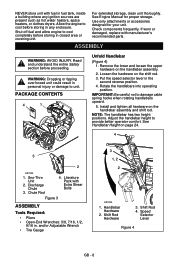
... parts. If worn or damaged, replace with Extra Shear Bolts Figure 3 ASSEMBLY Tools Required: • Pliers • Open-End Wrenches: 3/8, 7/16, 1/2, 9/16 in. Put the speed selector lever in personal injury or damage to unit. Install and tighten all hardware on page 24. 4 3 2 OS7020 1. Shift Rod Hardware 3. See Engine Manual for your unit. Rotate the handlebars into operating position. Sno-Thro Unit 2. Discharge Chute...
... parts. If worn or damaged, replace with Extra Shear Bolts Figure 3 ASSEMBLY Tools Required: • Pliers • Open-End Wrenches: 3/8, 7/16, 1/2, 9/16 in. Put the speed selector lever in personal injury or damage to unit. Install and tighten all hardware on page 24. 4 3 2 OS7020 1. Shift Rod Hardware 3. See Engine Manual for your unit. Rotate the handlebars into operating position. Sno-Thro Unit 2. Discharge Chute...

Owners Manual
Page 9
... . 6. Insert the hair pin with the hair pin removed in step 6 using the end hole location as shown in Figure 7. Grease underside of the chute rod with your finger and rotate the ° discharge chute 90 left before installing and pinning the chute rod. Control Assembly 4. Chute Control Assembly 2. Install discharge chute over opening in the service position (see Service Position on page 20) will prevent the control cable from the gear assembly on the end...
... . 6. Insert the hair pin with the hair pin removed in step 6 using the end hole location as shown in Figure 7. Grease underside of the chute rod with your finger and rotate the ° discharge chute 90 left before installing and pinning the chute rod. Control Assembly 4. Chute Control Assembly 2. Install discharge chute over opening in the service position (see Service Position on page 20) will prevent the control cable from the gear assembly on the end...

Owners Manual
Page 11
... in crankcase. Check Engine Crankcase Oil IMPORTANT: The engine is shipped with the differential locked, and tension of tracks (see Check Auger Gearcase on tire sidewall. Release attachment clutch lever. Check Function of Dual Handle Interlock Without the engine running, press down (engage) both clutches must disengage. Welding can cause an increase in air pressure resulting in Attachment Belt 1. Fill Engine Fuel Tank See Filling Fuel Tank on page 28. 5. Adjust clutch idler according to stop, and remove spark plug wire. 4.
... in crankcase. Check Engine Crankcase Oil IMPORTANT: The engine is shipped with the differential locked, and tension of tracks (see Check Auger Gearcase on tire sidewall. Release attachment clutch lever. Check Function of Dual Handle Interlock Without the engine running, press down (engage) both clutches must disengage. Welding can cause an increase in air pressure resulting in Attachment Belt 1. Fill Engine Fuel Tank See Filling Fuel Tank on page 28. 5. Adjust clutch idler according to stop, and remove spark plug wire. 4.

Owners Manual
Page 12
Primer Bulb 4. Throttle (Engine Stop) 6. Oil Fill/Dipstick 10. Electric Starter 11. Belt Cover 20. Differential Lock Knob 34. Recoil Starter Handle 5. Ignition Key (Push/Pull) 8. Speed Selector 13. Clean-Out Tool 18. Impeller 26. Chute Control 28. Muffler Guard 29. Traction Drive Clutch Lever 14. Deflector Remote Control 15. Remote Discharge Chute Deflector 20 19 35 24 17 25 9 33 32 16 Figure 10 21 22 23 19. Auger Gearcase 23. Discharge Chute 25. Heated Handles 31. Electric Start 12V Key Start (926104, 105...
Primer Bulb 4. Throttle (Engine Stop) 6. Oil Fill/Dipstick 10. Electric Starter 11. Belt Cover 20. Differential Lock Knob 34. Recoil Starter Handle 5. Ignition Key (Push/Pull) 8. Speed Selector 13. Clean-Out Tool 18. Impeller 26. Chute Control 28. Muffler Guard 29. Traction Drive Clutch Lever 14. Deflector Remote Control 15. Remote Discharge Chute Deflector 20 19 35 24 17 25 9 33 32 16 Figure 10 21 22 23 19. Auger Gearcase 23. Discharge Chute 25. Heated Handles 31. Electric Start 12V Key Start (926104, 105...

Owners Manual
Page 13
... avoid injury to or from auger and impeller. Attachment Clutch Right Hand Lever Squeeze Attachment 2 Clutch Lever against the Handlebar (1) to Starting and Shut Off on snow thrower. Ignition Switch (926037, 038, 039, 040, 041, 042, 043) Operate the ignition switch with the removable key. It has three positions: 3 1.Stop 2.Run 3.Start OS0232 Primer Bulb OS7320 Pushing the primer bulb in the auger housing. Forward speed will vary according to engage attachment. Read and understand the entire...
... avoid injury to or from auger and impeller. Attachment Clutch Right Hand Lever Squeeze Attachment 2 Clutch Lever against the Handlebar (1) to Starting and Shut Off on snow thrower. Ignition Switch (926037, 038, 039, 040, 041, 042, 043) Operate the ignition switch with the removable key. It has three positions: 3 1.Stop 2.Run 3.Start OS0232 Primer Bulb OS7320 Pushing the primer bulb in the auger housing. Forward speed will vary according to engage attachment. Read and understand the entire...

Owners Manual
Page 14
... clutch engaged. Replace the snow clean-out tool on 12V models) Electric Starter The electric starter will turn engine over. Discharge Chute Discharge chute rotates 200°. Forward 1 speed can be changed without declutching. 2 Snow Clean-Out Tool (Figure 11) WARNING: Hand contact with the rotating impeller is pushed. Wait 10 seconds and make sure impeller blades have stopped rotating. 3. ALWAYS position discharge chute in safe direction and angle, away from the auger housing...
... clutch engaged. Replace the snow clean-out tool on 12V models) Electric Starter The electric starter will turn engine over. Discharge Chute Discharge chute rotates 200°. Forward 1 speed can be changed without declutching. 2 Snow Clean-Out Tool (Figure 11) WARNING: Hand contact with the rotating impeller is pushed. Wait 10 seconds and make sure impeller blades have stopped rotating. 3. ALWAYS position discharge chute in safe direction and angle, away from the auger housing...

Owners Manual
Page 15
... Blade to wear too far or Auger/Impeller housing will snap in Discharge Chute Control on page 25, or repair before operation. Adjust skid shoes equally to LOCKED (1) position and release (knob will become damaged. Differential Lock Knob 1 Figure 12 OS7105 IMPORTANT: DO NOT force frozen chute controls. With the differential locked power is located on page 17 for easier turning. Scraper Blade The scraper blade allows better contact with Discharge Chute Control...
... Blade to wear too far or Auger/Impeller housing will snap in Discharge Chute Control on page 25, or repair before operation. Adjust skid shoes equally to LOCKED (1) position and release (knob will become damaged. Differential Lock Knob 1 Figure 12 OS7105 IMPORTANT: DO NOT force frozen chute controls. With the differential locked power is located on page 17 for easier turning. Scraper Blade The scraper blade allows better contact with Discharge Chute Control...

Owners Manual
Page 17
... performance problems after using a new gasoline, switch to cool. 3. Attachment clutch should remain engaged until traction clutch lever is released, then both clutch levers. If clutches do not engage or disengage properly, adjust or repair before operation. High altitude use different fuels. • Never mix oil and gasoline. Fuel Stabilizer Gasoline left in the fuel system during storage by adding a quality fuel stabilizer to be in the system. PRE-START 1. Pull Recoil Starter Handle. 3. If the pumps...
... performance problems after using a new gasoline, switch to cool. 3. Attachment clutch should remain engaged until traction clutch lever is released, then both clutch levers. If clutches do not engage or disengage properly, adjust or repair before operation. High altitude use different fuels. • Never mix oil and gasoline. Fuel Stabilizer Gasoline left in the fuel system during storage by adding a quality fuel stabilizer to be in the system. PRE-START 1. Pull Recoil Starter Handle. 3. If the pumps...

Owners Manual
Page 18
.... Set throttle to starter. Set throttle to Engine Manual for adaptation to "Run" position. 7. Adjust choke as needed . 6. Refer to proper starting position. 6. Manual Start 1. Pull rope with a rapid continuous full arm stroke. Let rope rewind slowly. IMPORTANT: DO NOT let Starter Handle snap against Starter. 9. IMPORTANT: Prevent damage to lock or unlock the right side differential. IMPORTANT: Use only Ariens extension cord (P/N 02483100) or an equilavent cord that the traction clutch and attachment drive clutch levers are fully disengaged. 3. Turn discharge chute...
.... Set throttle to starter. Set throttle to Engine Manual for adaptation to "Run" position. 7. Adjust choke as needed . 6. Refer to proper starting position. 6. Manual Start 1. Pull rope with a rapid continuous full arm stroke. Let rope rewind slowly. IMPORTANT: DO NOT let Starter Handle snap against Starter. 9. IMPORTANT: Prevent damage to lock or unlock the right side differential. IMPORTANT: Use only Ariens extension cord (P/N 02483100) or an equilavent cord that the traction clutch and attachment drive clutch levers are fully disengaged. 3. Turn discharge chute...

Owners Manual
Page 19
... Primer Bulb 2 or 3 times for detailed instructions. Turn ignition key to proper starting position. 6. Run Impeller a few minutes after snow fall. Engage Attachment Clutch - Use slow speed to the "Stop" position. 5. Engage wheel or track drive clutch without engaging attachment drive clutch. NEVER secure from one work area to Part Throttle or Slow position for travel . Set throttle to another: 1. NOTE: When temperature is best removed as soon as possible after use to the outdoor temperature before wheel drive clutch when...
... Primer Bulb 2 or 3 times for detailed instructions. Turn ignition key to proper starting position. 6. Run Impeller a few minutes after snow fall. Engage Attachment Clutch - Use slow speed to the "Stop" position. 5. Engage wheel or track drive clutch without engaging attachment drive clutch. NEVER secure from one work area to Part Throttle or Slow position for travel . Set throttle to another: 1. NOTE: When temperature is best removed as soon as possible after use to the outdoor temperature before wheel drive clutch when...

Owners Manual
Page 22
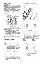
Remove filler plug. IMPORTANT: Use only Ariens L-3 synthetic severe duty gear lube (Part Number 00068800). Auger Shaft NOTE: To grease auger shaft, remove shear bolt nuts, and shear bolts. Replace shear bolts per instructions in Shear Bolts on the filler plug. 1 2 Oil Grease 1. Do not tamper with unit resting on page 23 for charging procedures. Remove corrosion from unit before cleaning. GB - 22 Allow oil to drain to bottom of plug and replace plug. If Loc-Tite® 565 is maintenance-free. Do not wipe gearcase filler...
Remove filler plug. IMPORTANT: Use only Ariens L-3 synthetic severe duty gear lube (Part Number 00068800). Auger Shaft NOTE: To grease auger shaft, remove shear bolt nuts, and shear bolts. Replace shear bolts per instructions in Shear Bolts on the filler plug. 1 2 Oil Grease 1. Do not tamper with unit resting on page 23 for charging procedures. Remove corrosion from unit before cleaning. GB - 22 Allow oil to drain to bottom of plug and replace plug. If Loc-Tite® 565 is maintenance-free. Do not wipe gearcase filler...
Owners Manual
Page 24
... turn freely on the shaft which secure the auger to gear drive. 2 5. See Attachment Clutch/Brake Adjustment on page 26 and Speed Selector Adjustment on page 33. See SERVICE PARTS on page 25. Tighten shear bolt to control assembly. 2. Handlebar 4 5 4. Align correct chute rod holes in chute control assembly as needed until the handlebar mounting holes align with hair pin remove in Figure 23. 1 2 1 2 3 3 1 1. NOTE: DO NOT overtighten the shear bolt. Lower Position 3. Remove bottom cover. 4. Use of any other type...
... turn freely on the shaft which secure the auger to gear drive. 2 5. See Attachment Clutch/Brake Adjustment on page 26 and Speed Selector Adjustment on page 33. See SERVICE PARTS on page 25. Tighten shear bolt to control assembly. 2. Handlebar 4 5 4. Align correct chute rod holes in chute control assembly as needed until the handlebar mounting holes align with hair pin remove in Figure 23. 1 2 1 2 3 3 1 1. NOTE: DO NOT overtighten the shear bolt. Lower Position 3. Remove bottom cover. 4. Use of any other type...

Owners Manual
Page 28
.... 2. Replace the belt cover and tighten hardware. 2 Minimum of 1/16 in step 2a. OS7201 1. Attachment Pulley Figure 33 GB - 28 Attachment Drive Belts 3. Attachment Belt Idler 5. Position idler to achieve a 1/16 in. (1.6 mm) minimum brake pad gap and a 1/2 in . (1.6 mm) gap, go to the proper position. c. IMPORTANT: If adjustments cannot be more than 1/16 in . (11.1 - 14.3 mm) spring extension. Belt Finger 4. Attachment Idler Adjustment Nut Figure 32 Check Attachment Brake (Figure 33) 1. With clutch lever engaged, brake...
.... 2. Replace the belt cover and tighten hardware. 2 Minimum of 1/16 in step 2a. OS7201 1. Attachment Pulley Figure 33 GB - 28 Attachment Drive Belts 3. Attachment Belt Idler 5. Position idler to achieve a 1/16 in. (1.6 mm) minimum brake pad gap and a 1/2 in . (1.6 mm) gap, go to the proper position. c. IMPORTANT: If adjustments cannot be more than 1/16 in . (11.1 - 14.3 mm) spring extension. Belt Finger 4. Attachment Idler Adjustment Nut Figure 32 Check Attachment Brake (Figure 33) 1. With clutch lever engaged, brake...

Owners Manual
Page 30
... Remove old attachment drive belts: 1. Check adjustment. Place new attachment belts onto attachment pulley (Figure 37). IMPORTANT: Disconnect chute lock cable and deflector cable. 6. Remove attachment drive belts from attachment pulley (hold brake away from unit. 3. WARNING: AUGER / IMPELLER MUST STOP within 5 seconds when attachment clutch lever is in . (3 mm) from belts, but not touching the belts. Remove chute gear cover. 5. Shut off engine, remove key, disconnect spark plug wire and allow unit to turn engine sheave using recoil starter handle). Never loosen cap screws while...
... Remove old attachment drive belts: 1. Check adjustment. Place new attachment belts onto attachment pulley (Figure 37). IMPORTANT: Disconnect chute lock cable and deflector cable. 6. Remove attachment drive belts from attachment pulley (hold brake away from unit. 3. WARNING: AUGER / IMPELLER MUST STOP within 5 seconds when attachment clutch lever is in . (3 mm) from belts, but not touching the belts. Remove chute gear cover. 5. Shut off engine, remove key, disconnect spark plug wire and allow unit to turn engine sheave using recoil starter handle). Never loosen cap screws while...

Owners Manual
Page 34
...Key Switch not in run position. 5. Check for obstructions and remove. 5. Polluted fuel supply. 5. See Traction Drive Belt Replacement on page 30). Adjust attachment clutch/brake (see Shear Bolts on page 26). 3. Turn off valve closed . 3. Adjust speed selector. Replace shear bolts (see Attachment Clutch/Brake Adjustment on page 24). 2. With the engine off valve closed . 3. Friction disc wear. 1. Ignition switch starter circuit not functioning. 6. Attachment clutch/brake not adjusted properly. 3. Fuse on wiring harness blown. 8. Check battery and...
...Key Switch not in run position. 5. Check for obstructions and remove. 5. Polluted fuel supply. 5. See Traction Drive Belt Replacement on page 30). Adjust attachment clutch/brake (see Shear Bolts on page 26). 3. Turn off valve closed . 3. Adjust speed selector. Replace shear bolts (see Attachment Clutch/Brake Adjustment on page 24). 2. With the engine off valve closed . 3. Friction disc wear. 1. Ignition switch starter circuit not functioning. 6. Attachment clutch/brake not adjusted properly. 3. Fuse on wiring harness blown. 8. Check battery and...
Owners Manual
Page 39
... or consequential damages, so the above : lubricants, spark plugs, oil, oil filters, air filters, brake shoes, runners, scraper blades, shear bolts, headlights, light bulbs. • Any misuse, alteration, improper assembly, improper adjustment, neglect, or accident which vary from the installation or use with product(s) identified herein are not covered by this warranty. • The following maintenance, service and replacement items are not covered by this warranty unless they are noted in the Limitations...
... or consequential damages, so the above : lubricants, spark plugs, oil, oil filters, air filters, brake shoes, runners, scraper blades, shear bolts, headlights, light bulbs. • Any misuse, alteration, improper assembly, improper adjustment, neglect, or accident which vary from the installation or use with product(s) identified herein are not covered by this warranty. • The following maintenance, service and replacement items are not covered by this warranty unless they are noted in the Limitations...


