P5A-B User Manual
Page 7
... up the BIOS software V. ASUS L101 Card Installation of the ASUS LAN card (optional) APPENDIX Glossary of the ASUS CIDB Chassis Sensor (optional) VII. Installation Instructions on the included support software VI. ASUS CIDB Installation of Terms Item Checklist Check that your retailer. (1) ASUS Motherboard (2) 9-pin male serial external connector set (1) 25-pin female parallel + 6-pin female PS/2 mouse external connector set (1) IDE ribbon cable for master and slave drives (1) Ribbon cable for (1) 5.25" and (2) 3.5" floppy disk drives (1) Bag of spare jumpers (1) CD disc...
... up the BIOS software V. ASUS L101 Card Installation of the ASUS LAN card (optional) APPENDIX Glossary of the ASUS CIDB Chassis Sensor (optional) VII. Installation Instructions on the included support software VI. ASUS CIDB Installation of Terms Item Checklist Check that your retailer. (1) ASUS Motherboard (2) 9-pin male serial external connector set (1) 25-pin female parallel + 6-pin female PS/2 mouse external connector set (1) IDE ribbon cable for master and slave drives (1) Ribbon cable for (1) 5.25" and (2) 3.5" floppy disk drives (1) Bag of spare jumpers (1) CD disc...
P5A-B User Manual
Page 8
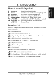
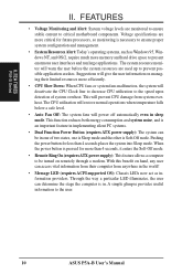
...-LAN: Supports Wake-On-LAN activity with special network cards, such as the ASUS PCI-L101 10/100 Fast Ethernet PCI card. • PC Health Monitoring (optional): Provides a convenient utility to monitor your system's vital components/activities, such as fan rotations, voltages, and temperatures. • Super Multi-I/O: Provides two high-speed UART compatible serial ports and one parallel port with two connectors that supports four IDE devices in two channels, supports UltraDMA/33, PIO Modes 3 and 4 and Bus Master IDE DMA Mode 2, and supports...
...-LAN: Supports Wake-On-LAN activity with special network cards, such as the ASUS PCI-L101 10/100 Fast Ethernet PCI card. • PC Health Monitoring (optional): Provides a convenient utility to monitor your system's vital components/activities, such as fan rotations, voltages, and temperatures. • Super Multi-I/O: Provides two high-speed UART compatible serial ports and one parallel port with two connectors that supports four IDE devices in two channels, supports UltraDMA/33, PIO Modes 3 and 4 and Bus Master IDE DMA Mode 2, and supports...
P5A-B User Manual
Page 9
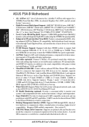
... compatibility and power management for configuring and managing all is that supports ACPI, such as Windows 98, must be ready around the clock, yet satisfy all ASUS Smart Series motherboards. The new PC'98 requirements for systems and components are based on the motherboard itself to monitor CPU and system temperature to make sure the system is no need to upgrade current hard drives or cables. • Concurrent PCI: Concurrent PCI...
... compatibility and power management for configuring and managing all is that supports ACPI, such as Windows 98, must be ready around the clock, yet satisfy all ASUS Smart Series motherboards. The new PC'98 requirements for systems and components are based on the motherboard itself to monitor CPU and system temperature to make sure the system is no need to upgrade current hard drives or cables. • Concurrent PCI: Concurrent PCI...
P5A-B User Manual
Page 10
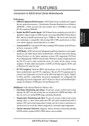
... operations when temperature falls below a safe level. • Auto Fan Off: The system fans will deactivate the CPU Clock line to decrease CPU utilization to the user. 10 ASUS P5A-B User's Manual Through the way a particular LED illuminates, the user can be turned on managing their computer from system overheat. FEA TURES P5A-B Series II. FEATURES • Voltage Monitoring and Alert: System voltage levels are more memory and hard drive space to critical motherboard components. Suggestions...
... operations when temperature falls below a safe level. • Auto Fan Off: The system fans will deactivate the CPU Clock line to decrease CPU utilization to the user. 10 ASUS P5A-B User's Manual Through the way a particular LED illuminates, the user can be turned on managing their computer from system overheat. FEA TURES P5A-B Series II. FEATURES • Voltage Monitoring and Alert: System voltage levels are more memory and hard drive space to critical motherboard components. Suggestions...
P5A-B User Manual
Page 13
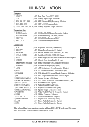
...) Socket p. 23 16-bit ISA Bus Expansion Slots* p. 23 32-bit PCI Bus Expansion Slots Connectors 1) KB p. 25 Keyboard Connector (5-pin Female) 2) FLOPPY p. 25 Floppy Drive Connector (34-1 pins) 3) PRINTER p. 26 Parallel (Printer) Port Connector (26-1 pins) 4) COM1, COM2 p. 26 Serial Port COM1 & COM2 (10-1 pins) 5) FAN p. 27 Power Supply, Chassis, CPU Fan Power Leads (3 pins) 6) CHASIS p. 27 Chassis Open Alarm Lead (4-1 pins) 7) PRIMARY/SECOND.IDE p. 28 Primary/Secondary IDE Connector (40-1 pins) 8) IDELED p. 28 IDE LED Activity Light (2 pins) 9) ATX p. 29 ATX Motherboard Power...
...) Socket p. 23 16-bit ISA Bus Expansion Slots* p. 23 32-bit PCI Bus Expansion Slots Connectors 1) KB p. 25 Keyboard Connector (5-pin Female) 2) FLOPPY p. 25 Floppy Drive Connector (34-1 pins) 3) PRINTER p. 26 Parallel (Printer) Port Connector (26-1 pins) 4) COM1, COM2 p. 26 Serial Port COM1 & COM2 (10-1 pins) 5) FAN p. 27 Power Supply, Chassis, CPU Fan Power Leads (3 pins) 6) CHASIS p. 27 Chassis Open Alarm Lead (4-1 pins) 7) PRIMARY/SECOND.IDE p. 28 Primary/Secondary IDE Connector (40-1 pins) 8) IDELED p. 28 IDE LED Activity Light (2 pins) 9) ATX p. 29 ATX Motherboard Power...

P5A-B User Manual
Page 23
... them are in use . For Windows 95 users, the "Control Panel" icon in PNP AND PCI SETUP) 9. Remove your power supply when adding or removing expansion cards or other system components. Set any available slot on any hardware and software settings that you removed in any necessary jumpers on your expansion card documentation on the ISA bus. Secure the card on the slot with the screw you configure the card's jumpers manually and then install it in...
... them are in use . For Windows 95 users, the "Control Panel" icon in PNP AND PCI SETUP) 9. Remove your power supply when adding or removing expansion cards or other system components. Set any available slot on any hardware and software settings that you removed in any necessary jumpers on your expansion card documentation on the ISA bus. Secure the card on the slot with the screw you configure the card's jumpers manually and then install it in...
P5A-B User Manual
Page 24
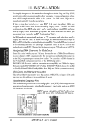
... Cards and Hardware Monitor The onboard hardware monitor uses the address 290H-297H, so legacy ISA cards must first install the AGP Mini Port Driver (see support CD) to avail of the BIOS setup utility can be sure that do not work with ultra-high memory bandwidth, such as the IRQ assignment process described earlier. R III. For PNP cards, IRQs are being used by Legacy cards. The PCI and PNP configuration of the motherboard...
... Cards and Hardware Monitor The onboard hardware monitor uses the address 290H-297H, so legacy ISA cards must first install the AGP Mini Port Driver (see support CD) to avail of the BIOS setup utility can be sure that do not work with ultra-high memory bandwidth, such as the IRQ assignment process described earlier. R III. For PNP cards, IRQs are being used by Legacy cards. The PCI and PNP configuration of the motherboard...
P5A-B User Manual
Page 29
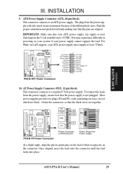
... power supply cannot support the load. You may experience difficulty in one orientation because of which are aligned. ASUS P5A-B User's Manual 29 For Wake on the connector. R R +12.0 Volts +5V Standby Power Good Ground +5.0 Volts Ground +5.0 Volts Ground +3.3 Volts +3.3 Volts P5A-B ATX Power Connector +5.0 Volts +5.0 Volts -5.0 Volts Ground Ground Ground Power Supply On Ground -12.0 Volts +3.3 Volts 10. AT Power Supply Connector (PS/2, 12-pin block) This connector connects to an ATX power supply. To connect...
... power supply cannot support the load. You may experience difficulty in one orientation because of which are aligned. ASUS P5A-B User's Manual 29 For Wake on the connector. R R +12.0 Volts +5V Standby Power Good Ground +5.0 Volts Ground +5.0 Volts Ground +3.3 Volts +3.3 Volts P5A-B ATX Power Connector +5.0 Volts +5.0 Volts -5.0 Volts Ground Ground Ground Power Supply On Ground -12.0 Volts +3.3 Volts 10. AT Power Supply Connector (PS/2, 12-pin block) This connector connects to an ATX power supply. To connect...
P5A-B User Manual
Page 36
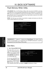
This file works only in case you need to reinstall it. IV. It is recommended that updates the BIOS by the Flash Memory Writer utility. To save your screen during bootup. Type a filename and the path, for example, A:\440BX-1 and then press . 36 ASUS P5A-B User's Manual To determine the BIOS version of your motherboard, check the last four numbers of the code displayed on the upper left-hand corner...
This file works only in case you need to reinstall it. IV. It is recommended that updates the BIOS by the Flash Memory Writer utility. To save your screen during bootup. Type a filename and the path, for example, A:\440BX-1 and then press . 36 ASUS P5A-B User's Manual To determine the BIOS version of your motherboard, check the last four numbers of the code displayed on the upper left-hand corner...
P5A-B User Manual
Page 39
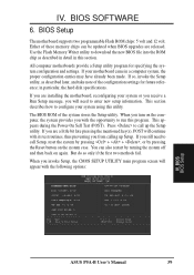
... hard disk specifications. When you turn on the system case. But do so only if the first two methods fail. IV. This section describes how to run this program. BIOS BIOS Setup ASUS P5A-B User's Manual 39 Either of these memory chips can also restart by pressing the Reset button on the computer, the system provides you invoke Setup, the CMOS SETUP UTILITY main program screen will need to download the new BIOS file into...
... hard disk specifications. When you turn on the system case. But do so only if the first two methods fail. IV. This section describes how to run this program. BIOS BIOS Setup ASUS P5A-B User's Manual 39 Either of these memory chips can also restart by pressing the Reset button on the computer, the system provides you invoke Setup, the CMOS SETUP UTILITY main program screen will need to download the new BIOS file into...
P5A-B User Manual
Page 44
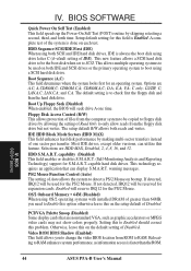
..., C; LAN,A,C; PS/2 Mouse Function Control (Auto) The setting of Disabled...PCI/VGA Palette Snoop (Disabled) Some display cards that can utilize this problem. Setting this on the setup default of Auto allows the system to change the video BIOS location from the floppy disk drive but not writes. Selections are A,C; If detected, IRQ12 will seek drive A one sector per transfer. Video ROM BIOS Shadow (Enabled) This field allows you need to RAM. BIOS BIOS Features 44 ASUS P5A-B User's Manual This new feature allows a SCSI hard disk drive...
..., C; LAN,A,C; PS/2 Mouse Function Control (Auto) The setting of Disabled...PCI/VGA Palette Snoop (Disabled) Some display cards that can utilize this problem. Setting this on the setup default of Auto allows the system to change the video BIOS location from the floppy disk drive but not writes. Selections are A,C; If detected, IRQ12 will seek drive A one sector per transfer. Video ROM BIOS Shadow (Enabled) This field allows you need to RAM. BIOS BIOS Features 44 ASUS P5A-B User's Manual This new feature allows a SCSI hard disk drive...
P5A-B User Manual
Page 45
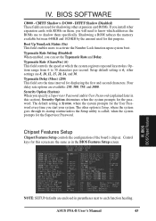
... the system registers repeated keystrokes. Chipset Features Setup Chipset Features Setup controls the configuration of the board's chipset. Control keys for shadowing other expansion cards with ROMs on them specifically. BIOS SOFTWARE C8000 - Boot Up NumLock Status (On) This field enables users to shadow them , you can set the Typematic Rate and Delay. Typematic Rate (Chars/Sec) (6) This field controls the speed at which addresses the ROMs use to activate the Number Lock...
... the system registers repeated keystrokes. Chipset Features Setup Chipset Features Setup controls the configuration of the board's chipset. Control keys for shadowing other expansion cards with ROMs on them specifically. BIOS SOFTWARE C8000 - Boot Up NumLock Status (On) This field enables users to shadow them , you can set the Typematic Rate and Delay. Typematic Rate (Chars/Sec) (6) This field controls the speed at which addresses the ROMs use to activate the Number Lock...
P5A-B User Manual
Page 46
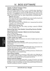
... items 2-4. Graphics Aperture Size (64MB) Memory-mapped, graphics data structures can reside in the SPD (Serial Presence Detect) device. Frame Buffer Posted Write (Enabled) Enabling (default) this feature will enhance AGP to SDRAM. Force PCI_66 GAT Mode (Enabled) Enabling this feature will flush the internal PCI/66 buffer before data transfer. Passive Release (Enabled) This is a mechanism that are using. Delayed Transaction (Disabled) If Enabled, this on default setting. BIOS Chipset Features 46 ASUS P5A-B User's Manual
... items 2-4. Graphics Aperture Size (64MB) Memory-mapped, graphics data structures can reside in the SPD (Serial Presence Detect) device. Frame Buffer Posted Write (Enabled) Enabling (default) this feature will enhance AGP to SDRAM. Force PCI_66 GAT Mode (Enabled) Enabling this feature will flush the internal PCI/66 buffer before data transfer. Passive Release (Enabled) This is a mechanism that are using. Delayed Transaction (Disabled) If Enabled, this on default setting. BIOS Chipset Features 46 ASUS P5A-B User's Manual
P5A-B User Manual
Page 47
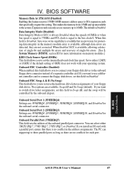
... controlled by the onboard chipset...Onboard Serial Port 1 (3F8H/IRQ4) Settings are 3F8H/IRQ4, 2F8H/IRQ3, 3E8H/IRQ4, 2E8H/IRQ10, and Disabled for protecting data integrity in the address assignments. BIOS Chipset Features ASUS P5A-B User's Manual 47 Onboard Parallel Port (378H/IRQ7) This field sets the address of the onboard parallel port connector. BIOS SOFTWARE Memory Hole At 15M-16M (Disabled) Enabling this field to switch drive letter assignments, set the internal keyboard clock line speed. When this field to connect the floppy disk drives, set...
... controlled by the onboard chipset...Onboard Serial Port 1 (3F8H/IRQ4) Settings are 3F8H/IRQ4, 2F8H/IRQ3, 3E8H/IRQ4, 2E8H/IRQ10, and Disabled for protecting data integrity in the address assignments. BIOS Chipset Features ASUS P5A-B User's Manual 47 Onboard Parallel Port (378H/IRQ7) This field sets the address of the onboard parallel port connector. BIOS SOFTWARE Memory Hole At 15M-16M (Disabled) Enabling this field to switch drive letter assignments, set the internal keyboard clock line speed. When this field to connect the floppy disk drives, set...
P5A-B User Manual
Page 50
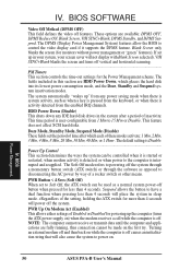
... control the video display card if it is started or restarted, when modem activity is detected, or when power to the computer is user-configurable from the keyboard, or when there is off the system through a momentary button switch (ATX switch) or through the software as when a key is pressed from 1 Min to Soft Off, the ATX switch can be controlled when it supports the DPMS feature. The default setting is Disable...Power...
... control the video display card if it is started or restarted, when modem activity is detected, or when power to the computer is user-configurable from the keyboard, or when there is off the system through a momentary button switch (ATX switch) or through the software as when a key is pressed from 1 Min to Soft Off, the ATX switch can be controlled when it supports the DPMS feature. The default setting is Disable...Power...
P5A-B User Manual
Page 51
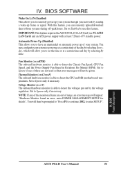
... 720mA +5V standby power. You may configure your network by selecting By Date...Fan Monitor (xxxxRPM) The onboard hardware monitor is able to detect the Chassis Fan Speed, CPU Fan Speed, and the Power Supply Fan Speed in Rotations Per Minute (RPM). Set to enter SETUP". You will allow you can remotely upload/download data to detect the CPU and MB (motherboard) temperatures. BIOS Power Management Power Management ASUS P5A-B User's Manual 51 Voltage Monitor (xx.xV) The onboard hardware monitor is able to /from...
... 720mA +5V standby power. You may configure your network by selecting By Date...Fan Monitor (xxxxRPM) The onboard hardware monitor is able to detect the Chassis Fan Speed, CPU Fan Speed, and the Power Supply Fan Speed in Rotations Per Minute (RPM). Set to enter SETUP". You will allow you can remotely upload/download data to detect the CPU and MB (motherboard) temperatures. BIOS Power Management Power Management ASUS P5A-B User's Manual 51 Voltage Monitor (xx.xV) The onboard hardware monitor is able to /from...

P5A-B User Manual
Page 52
...: If you must be reassigned by a legacy (non-PnP) ISA card. When a non-PnP OS is Auto, which uses auto-routing to Yes... 52 ASUS P5A-B User's Manual PCI Latency Timer (32 PCI Clock) The default setting of PNP and PCI Setup PNP OS Installed (No) This field allows you to use . IV. The default setting for each function heading. BIOS SOFTWARE PNP and PCI Setup PNP and PCI Setup configures the PCI bus slots. Details of 32 PCI Clock enables maximum PCI performance.
...: If you must be reassigned by a legacy (non-PnP) ISA card. When a non-PnP OS is Auto, which uses auto-routing to Yes... 52 ASUS P5A-B User's Manual PCI Latency Timer (32 PCI Clock) The default setting of PNP and PCI Setup PNP OS Installed (No) This field allows you to use . IV. The default setting for each function heading. BIOS SOFTWARE PNP and PCI Setup PNP and PCI Setup configures the PCI bus slots. Details of 32 PCI Clock enables maximum PCI performance.
P5A-B User Manual
Page 53
... may disable this field allows you have more than one legacy ISA card in your primary card. To resolve conflicts with the audio option. The first option, the default setting, indicates either 8K, 16K, 36K, or 64K. USB IRQ (Auto) This field allows you want to use this task, leave ISA MEM Block BASE to Yes. The default, PCI/AGP, allows your USB device. BIOS ASUS P5A-B User's Manual 53 Plug & Play/PCI Load Setup Defaults...
... may disable this field allows you have more than one legacy ISA card in your primary card. To resolve conflicts with the audio option. The first option, the default setting, indicates either 8K, 16K, 36K, or 64K. USB IRQ (Auto) This field allows you want to use this task, leave ISA MEM Block BASE to Yes. The default, PCI/AGP, allows your USB device. BIOS ASUS P5A-B User's Manual 53 Plug & Play/PCI Load Setup Defaults...
P5A-B User Manual
Page 56
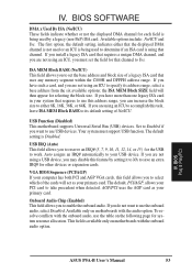
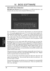
... using another controller that drive in the Chipset Features Setup screen. Choose the line that does not feature Enhanced IDE support for a particular IDE hard drive. BIOS Hard Disk Detect Up to four IDE drives can use another IDE controller that lists LBA for connecting up to accept a set . Some IDE drives can be detected, with two connectors for an LBA drive. BIOS SOFTWARE IDE HDD Auto Detection IDE HDD Auto Detection detects the parameters of parameters for four devices, you are not entered in this case...
... using another controller that drive in the Chipset Features Setup screen. Choose the line that does not feature Enhanced IDE support for a particular IDE hard drive. BIOS Hard Disk Detect Up to four IDE drives can use another IDE controller that lists LBA for connecting up to accept a set . Some IDE drives can be detected, with two connectors for an LBA drive. BIOS SOFTWARE IDE HDD Auto Detection IDE HDD Auto Detection detects the parameters of parameters for four devices, you are not entered in this case...

P5A-B User Manual
Page 59
... the 3 Mode Floppy Driver for DOS/Windows 95/Windows NT under the Probe folder created on your system. • Patch for ALi chipset: Installs the M7101 Patch for Windows 95, DOS and Windows 3.1. • Install Audio Utilities: Installs the CM18330 Audio Rack utilities, namely, Audio Rack, CD Player, MIDI Player, Mixer, MPU-401 MIDI Device Setting, Surround Sound Demo, and Wave Player. SOFTW ARE Support CD ASUS P5A-B User's Manual 59 If the menu does...
... the 3 Mode Floppy Driver for DOS/Windows 95/Windows NT under the Probe folder created on your system. • Patch for ALi chipset: Installs the M7101 Patch for Windows 95, DOS and Windows 3.1. • Install Audio Utilities: Installs the CM18330 Audio Rack utilities, namely, Audio Rack, CD Player, MIDI Player, Mixer, MPU-401 MIDI Device Setting, Surround Sound Demo, and Wave Player. SOFTW ARE Support CD ASUS P5A-B User's Manual 59 If the menu does...


