P5A-B User Manual
Page 1
R P5A-B Pentium® Super7 Motherboard USER'S MANUAL
R P5A-B Pentium® Super7 Motherboard USER'S MANUAL
P5A-B User Manual
Page 4
INSTALLATION 12 ASUS P5A-B Motherboard Layout 12 Installation Steps 14 1. System Memory (DIMM 19 DIMM Memory Installation Procedures 20 3. Central Processing Unit (CPU 21 4. CONTENTS I. Jumpers ... Power Management Setup 49 Details of Power Management Setup 49 PNP and PCI Setup 52 Details of the ASUS P5A-B Motherboard 11 III. FEATURES 8 ASUS P5A-B Motherboard 8 Introduction to ASUS Smart Series Motherboards 9 Parts of PNP and PCI Setup 52 4 ASUS P5A-B User's Manual INTRODUCTION 7 How this Manual is Organized 7 Item Checklist 7 II. External Connectors 25 ...
INSTALLATION 12 ASUS P5A-B Motherboard Layout 12 Installation Steps 14 1. System Memory (DIMM 19 DIMM Memory Installation Procedures 20 3. Central Processing Unit (CPU 21 4. CONTENTS I. Jumpers ... Power Management Setup 49 Details of Power Management Setup 49 PNP and PCI Setup 52 Details of the ASUS P5A-B Motherboard 11 III. FEATURES 8 ASUS P5A-B Motherboard 8 Introduction to ASUS Smart Series Motherboards 9 Parts of PNP and PCI Setup 52 4 ASUS P5A-B User's Manual INTRODUCTION 7 How this Manual is Organized 7 Item Checklist 7 II. External Connectors 25 ...
P5A-B User Manual
Page 5
... Motherboard Support CD 59 Desktop Management Interface (DMI 60 Introducing the ASUS DMI Configuration Utility 60 Starting the ASUS DMI Configuration Utility 60 Using the ASUS DMI Configuration Utility 61 VI. ASUS LAN Card 65 ASUS PCI-L101 Fast Ethernet Card 65 Features 66 Software Driver Support 66 Question and Answer 66 APPENDIX 67 Glossary 67 ASUS P5A...
... Motherboard Support CD 59 Desktop Management Interface (DMI 60 Introducing the ASUS DMI Configuration Utility 60 Starting the ASUS DMI Configuration Utility 60 Using the ASUS DMI Configuration Utility 61 VI. ASUS LAN Card 65 ASUS PCI-L101 Fast Ethernet Card 65 Features 66 Software Driver Support 66 Question and Answer 66 APPENDIX 67 Glossary 67 ASUS P5A...
P5A-B User Manual
Page 7
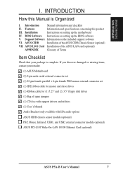
...) PS/2 Mouse, Infrared, USB1, and USB2 external connector module (optional) ASUS PCI-L101 Wake-On-LAN 10/100 Ethernet Card (optional) ASUS P5A-B User's Manual 7 ASUS L101 Card Installation of the ASUS LAN card (optional) APPENDIX Glossary of Terms Item Checklist Check that your retailer. (1) ASUS Motherboard (2) 9-pin male serial external connector set (1) 25-pin female parallel...
...) PS/2 Mouse, Infrared, USB1, and USB2 external connector module (optional) ASUS PCI-L101 Wake-On-LAN 10/100 Ethernet Card (optional) ASUS P5A-B User's Manual 7 ASUS L101 Card Installation of the ASUS LAN card (optional) APPENDIX Glossary of Terms Item Checklist Check that your retailer. (1) ASUS Motherboard (2) 9-pin male serial external connector set (1) 25-pin female parallel...
P5A-B User Manual
Page 8
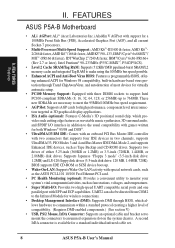
... DMI-enabled components.) (See section V) • USB, PS/2 Mouse, IrDA Connector: Supports an optional cable and bracket set . 8 ASUS P5A-B User's Manual These new SDRAMs are necessary to meet the 95MHz/100MHz bus speed requirement. • AGP Slot: Supports AGP cards for ... rotations, voltages, and temperatures. • Super Multi-I /O interface in addition to an unused expansion slot on the system chassis. II. FEATURES ASUS P5A-B Motherboard • ALi AGPset: ALi® (Acer Laboratories Inc.) Aladdin V AGPset with EPP and ECP capabilities. Supports Japanese "Floppy 3 mode" (3.5-...
... DMI-enabled components.) (See section V) • USB, PS/2 Mouse, IrDA Connector: Supports an optional cable and bracket set . 8 ASUS P5A-B User's Manual These new SDRAMs are necessary to meet the 95MHz/100MHz bus speed requirement. • AGP Slot: Supports AGP cards for ... rotations, voltages, and temperatures. • Super Multi-I /O interface in addition to an unused expansion slot on the system chassis. II. FEATURES ASUS P5A-B Motherboard • ALi AGPset: ALi® (Acer Laboratories Inc.) Aladdin V AGPset with EPP and ECP capabilities. Supports Japanese "Floppy 3 mode" (3.5-...
P5A-B User Manual
Page 9
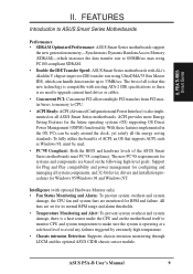
...are based on all system components, and 32-bit device drivers and installation procedures for configuring and managing all ASUS Smart Series motherboards. All fans are set for its normal RPM range and alarm thresholds. • Temperature Monitoring and Alert...ASUS P5A-B User's Manual 9 The new PC'98 requirements for systems and components are monitored for the future operating systems (OS) supporting OS Direct Power Management (OSPM) functionality. FEATURES Introduction to ASUS Smart Series Motherboards Performance • SDRAM Optimized Performance: ASUS Smart Series motherboards ...
...are based on all system components, and 32-bit device drivers and installation procedures for configuring and managing all ASUS Smart Series motherboards. All fans are set for its normal RPM range and alarm thresholds. • Temperature Monitoring and Alert...ASUS P5A-B User's Manual 9 The new PC'98 requirements for systems and components are monitored for the future operating systems (OS) supporting OS Direct Power Management (OSPM) functionality. FEATURES Introduction to ASUS Smart Series Motherboards Performance • SDRAM Optimized Performance: ASUS Smart Series motherboards ...
P5A-B User Manual
Page 10
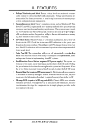
...management. • System Resources Alert: Today's operating systems, such as information providers. Voltage specifications are used up to the user. 10 ASUS P5A-B User's Manual This will power off automatically even in . The CPU utilization will restore normal operations when temperature falls below a safe level....the system will warn the user before the system resources are more critical for more memory and hard drive space to critical motherboard components. With this benefit on remotely through a modem. The system resource monitor will deactivate the CPU Clock line to decrease...
...management. • System Resources Alert: Today's operating systems, such as information providers. Voltage specifications are used up to the user. 10 ASUS P5A-B User's Manual This will power off automatically even in . The CPU utilization will restore normal operations when temperature falls below a safe level....the system will warn the user before the system resources are more critical for more memory and hard drive space to critical motherboard components. With this benefit on remotely through a modem. The system resource monitor will deactivate the CPU Clock line to decrease...
P5A-B User Manual
Page 11
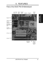
FEATURES Parts of the ASUS P5A-B Motherboard Serial Parallel 3 DIMM ALi Aladdin V Ports Port Sockets AGPset ATX Power AT Connector CPU ZIF Socket 7 Keyboard USB/MIR Floppy/IDE Connectors 512KB/1024KB Pipelined Burst L2 Cache Accelerated Graphics Port 3 PCI Slots 2 ISA Slots Programmable Flash ROM IrDA C-Media 3D Positional Sound Chip (optional) ASUS P5A-B User's Manual 11 II. FEA TURES Motherboard Parts II.
FEATURES Parts of the ASUS P5A-B Motherboard Serial Parallel 3 DIMM ALi Aladdin V Ports Port Sockets AGPset ATX Power AT Connector CPU ZIF Socket 7 Keyboard USB/MIR Floppy/IDE Connectors 512KB/1024KB Pipelined Burst L2 Cache Accelerated Graphics Port 3 PCI Slots 2 ISA Slots Programmable Flash ROM IrDA C-Media 3D Positional Sound Chip (optional) ASUS P5A-B User's Manual 11 II. FEA TURES Motherboard Parts II.

P5A-B User Manual
Page 12
INSTALLATION ASUS P5A-B Motherboard Layout AT Keyboard Connector KB USB, PS/2 Mouse, IrDA COM 1 COM 2 Parallel Port Row 5 4 3 2 1 0 VIO1 AT Power Connector VIO0 FS3 FS2 PWR_FAN FS1 FS0 ATX ... BIOS) C-Media 3D Positional Sound Chip (optional) VID3 VID2 VID1 VID0 CHA_FAN SPDI SPDO TTL ISA Slot 2 IDELED IR + Panel Connectors III. III. INST ALLATION Motherboard Layout 12 ASUS P5A-B User's Manual
INSTALLATION ASUS P5A-B Motherboard Layout AT Keyboard Connector KB USB, PS/2 Mouse, IrDA COM 1 COM 2 Parallel Port Row 5 4 3 2 1 0 VIO1 AT Power Connector VIO0 FS3 FS2 PWR_FAN FS1 FS0 ATX ... BIOS) C-Media 3D Positional Sound Chip (optional) VID3 VID2 VID1 VID0 CHA_FAN SPDI SPDO TTL ISA Slot 2 IDELED IR + Panel Connectors III. III. INST ALLATION Motherboard Layout 12 ASUS P5A-B User's Manual
P5A-B User Manual
Page 13
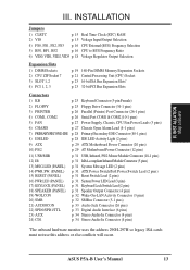
INST ALLATION Map of Board III. ASUS P5A-B User's Manual 13 III. INSTALLATION Jumpers 1) CLRTC p. 15 Real Time Clock (RTC) RAM 2) VIO p. 15 Voltage Input/Output Selection 4) FS0, FS1, FS2, FS3 p. 16 CPU ... (4-1 pins) 7) PRIMARY/SECOND.IDE p. 28 Primary/Secondary IDE Connector (40-1 pins) 8) IDELED p. 28 IDE LED Activity Light (2 pins) 9) ATX p. 29 ATX Motherboard Power Connector (20 pins) 10) PS/2 p. 29 AT Motherboard Power Connector (12 pins) 11) USB/MIR p. 31 USB, Infrared, PS/2 Mouse Module Connector (18-1 pins) 12) IR p. 31 IrDA-compliant...
INST ALLATION Map of Board III. ASUS P5A-B User's Manual 13 III. INSTALLATION Jumpers 1) CLRTC p. 15 Real Time Clock (RTC) RAM 2) VIO p. 15 Voltage Input/Output Selection 4) FS0, FS1, FS2, FS3 p. 16 CPU ... (4-1 pins) 7) PRIMARY/SECOND.IDE p. 28 Primary/Secondary IDE Connector (40-1 pins) 8) IDELED p. 28 IDE LED Activity Light (2 pins) 9) ATX p. 29 ATX Motherboard Power Connector (20 pins) 10) PS/2 p. 29 AT Motherboard Power Connector (12 pins) 11) USB/MIR p. 31 USB, Infrared, PS/2 Mouse Module Connector (18-1 pins) 12) IR p. 31 IrDA-compliant...

P5A-B User Manual
Page 14
... on the Motherboard 2. III. Install System Memory Modules 3. Jumpers WARNING! INSTALLATION Installation Steps Before using your computer, you do not have one, touch both of your computer. 1. Install Expansion Cards 5. Use a grounded wrist strap before handling computer components. Connect Ribbon Cables, Cabinet Wires, and Power Supply 6. INST ALLATION Jumpers 14 ASUS P5A-B User...
... on the Motherboard 2. III. Install System Memory Modules 3. Jumpers WARNING! INSTALLATION Installation Steps Before using your computer, you do not have one, touch both of your computer. 1. Install Expansion Cards 5. Use a grounded wrist strap before handling computer components. Connect Ribbon Cables, Cabinet Wires, and Power Supply 6. INST ALLATION Jumpers 14 ASUS P5A-B User...
P5A-B User Manual
Page 17
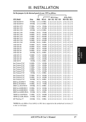
... [2-3] [1-2] [2-3] [2-3] [2-3] [1-2] [2-3] [2-3] [2-3] [1-2] [2-3] [2-3] [2-3] [2-3] [2-3] [2-3] [2-3] [1-2] [2-3] [2-3] [2-3] [1-2] [2-3] [2-3] [2-3] [2-3] [2-3] [2-3] [2-3] (Freq. BUS F. ASUS P5A-B User's Manual 17 INSTALLATION Set the jumpers by the Internal speed of your CPU as follows: CPU Model Freq. Mult.) BF0 BF1 BF2... [2-3] [1-2] [----] [2-3] [1-2] [----] [2-3] [1-2] [2-3] *NOTE:The only IBM or Cyrix 6x86(L) (or M I) that is supported on this motherboard is revision 2.7 or later (see next page). III. AMD-K6-III/450 AMD-K6-III/400 450MHz 400MHz AMD-K6-2/475 AMD-K6-2/...
... [2-3] [1-2] [2-3] [2-3] [2-3] [1-2] [2-3] [2-3] [2-3] [1-2] [2-3] [2-3] [2-3] [2-3] [2-3] [2-3] [2-3] [1-2] [2-3] [2-3] [2-3] [1-2] [2-3] [2-3] [2-3] [2-3] [2-3] [2-3] [2-3] (Freq. BUS F. ASUS P5A-B User's Manual 17 INSTALLATION Set the jumpers by the Internal speed of your CPU as follows: CPU Model Freq. Mult.) BF0 BF1 BF2... [2-3] [1-2] [----] [2-3] [1-2] [----] [2-3] [1-2] [2-3] *NOTE:The only IBM or Cyrix 6x86(L) (or M I) that is supported on this motherboard is revision 2.7 or later (see next page). III. AMD-K6-III/450 AMD-K6-III/400 450MHz 400MHz AMD-K6-2/475 AMD-K6-2/...
P5A-B User Manual
Page 18
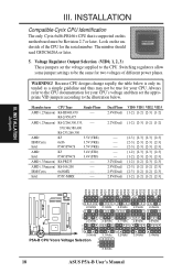
... VID3 VID0 VID1 VID2 VID3 VID0 VID1 VID2 VID3 1 2 3 2.0Volts 2.1Volts 1 2 3 2.5Volts 2.6Volts 1 2 3 3.0Volts 3.1Volts P5A-B CPU Vcore Voltage Selection 1 2 3 3.5Volts 2.2Volts 2.7Volts 3.2Volts 2.3Volts 2.8Volts 3.3Volts 2.4Volts 2.9Volts 3.4Volts 18 ASUS P5A-B User's Manual Look on this motherboard must be Revision 2.7 or later. Switching regulators allow some jumper settings to be true for...
... VID3 VID0 VID1 VID2 VID3 VID0 VID1 VID2 VID3 1 2 3 2.0Volts 2.1Volts 1 2 3 2.5Volts 2.6Volts 1 2 3 3.0Volts 3.1Volts P5A-B CPU Vcore Voltage Selection 1 2 3 3.5Volts 2.2Volts 2.7Volts 3.2Volts 2.3Volts 2.8Volts 3.3Volts 2.4Volts 2.9Volts 3.4Volts 18 ASUS P5A-B User's Manual Look on this motherboard must be Revision 2.7 or later. Switching regulators allow some jumper settings to be true for...
P5A-B User Manual
Page 19
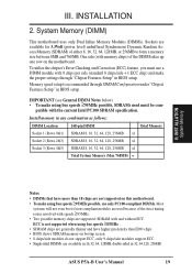
.... ASUS P5A-B User's Manual 19 Sockets are available in BIOS setup. IMPORTANT (see General DIMM Notes below) • To make using bus speeds ≥83MHz . • SDRAM chips are generally thinner and have higher pin density than EDO chips. • BIOS shows SDRAM memory on the motherboard. ... feature, you must be com- INSTALLATION 2. INST ALLATION System Memory Notes • DIMMs that have more than 18 chips are not supported on this motherboard. • To make using bus speeds ≥95MHz possible, SDRAMs used because of either 8, 16, 32, 64, 128MB, or 256MB to form...
.... ASUS P5A-B User's Manual 19 Sockets are available in BIOS setup. IMPORTANT (see General DIMM Notes below) • To make using bus speeds ≥83MHz . • SDRAM chips are generally thinner and have higher pin density than EDO chips. • BIOS shows SDRAM memory on the motherboard. ... feature, you must be com- INSTALLATION 2. INST ALLATION System Memory Notes • DIMMs that have more than 18 chips are not supported on this motherboard. • To make using bus speeds ≥95MHz possible, SDRAMs used because of either 8, 16, 32, 64, 128MB, or 256MB to form...
P5A-B User Manual
Page 20
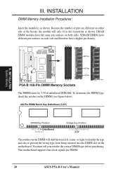
III. You must be 3.3Volt unbuffered SDRAMs. To determine the DIMM type, check the notches on the motherboard. SDRAM DIMMs have different pin contacts on each side and therefore have the same pin contacts on either side of the breaks, the module ...SIMM modules have a higher pin density. 88 Pins 60 Pins 20 Pins Lock P5A-B 168-Pin DIMM Memory Sockets The DIMMs must tell your retailer the correct DIMM type before purchasing. This motherboard supports four clock signals per DIMM. 20 ASUS P5A-B User's Manual INSTALLATION DIMM Memory Installation Procedures: Insert the module(s) as shown...
III. You must be 3.3Volt unbuffered SDRAMs. To determine the DIMM type, check the notches on the motherboard. SDRAM DIMMs have different pin contacts on each side and therefore have the same pin contacts on either side of the breaks, the module ...SIMM modules have a higher pin density. 88 Pins 60 Pins 20 Pins Lock P5A-B 168-Pin DIMM Memory Sockets The DIMMs must tell your retailer the correct DIMM type before purchasing. This motherboard supports four clock signals per DIMM. 20 ASUS P5A-B User's Manual INSTALLATION DIMM Memory Installation Procedures: Insert the module(s) as shown...
P5A-B User Manual
Page 21
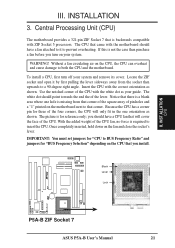
...for three of the four corners, the CPU will cover the face of the CPU with the correct orientation as shown. Blank Lever Lock R P5A-B ZIF Socket 7 ASUS P5A-B User's Manual 21 The picture is required to that corner of the square array of pin holes and a "1" printed on the CPU, the... for "BUS Frequency Selection" depending on the CPU that is not the case then purchase a fan before you install. Central Processing Unit (CPU) The motherboard provides a 321-pin ZIF Socket 7 that you turn off your system. The white dot should have a fan attached to it by first pulling the ...
...for three of the four corners, the CPU will cover the face of the CPU with the correct orientation as shown. Blank Lever Lock R P5A-B ZIF Socket 7 ASUS P5A-B User's Manual 21 The picture is required to that corner of the square array of pin holes and a "1" printed on the CPU, the... for "BUS Frequency Selection" depending on the CPU that is not the case then purchase a fan before you install. Central Processing Unit (CPU) The motherboard provides a 321-pin ZIF Socket 7 that you turn off your system. The white dot should have a fan attached to it by first pulling the ...

P5A-B User Manual
Page 23
... are already in the Windows directory to use at the same time. Secure the card on any available slot on the slot you unplug your motherboard and expansion cards. Make sure that you intend to one use the same IRQs or your used by parts of the system which leaves 6 free... severe damage to use . 5. System IRQs are two types of your computer will experience problems when those two devices are then used and free IRQs. ASUS P5A-B User's Manual 23
... are already in the Windows directory to use at the same time. Secure the card on any available slot on the slot you unplug your motherboard and expansion cards. Make sure that you intend to one use the same IRQs or your used by parts of the system which leaves 6 free... severe damage to use . 5. System IRQs are two types of your computer will experience problems when those two devices are then used and free IRQs. ASUS P5A-B User's Manual 23
P5A-B User Manual
Page 24
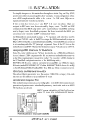
... the Plug and Play (PNP) specification which IRQs are assigned automatically from those used by Legacy cards. P5A-B Accelerated Graphics Port (AGP) 24 ASUS P5A-B User's Manual For older Legacy cards that the jumpers on this motherboard are set something called the INT (interrupt) assignment. ISA Cards and Hardware Monitor The onboard hardware monitor...
... the Plug and Play (PNP) specification which IRQs are assigned automatically from those used by Legacy cards. P5A-B Accelerated Graphics Port (AGP) 24 ASUS P5A-B User's Manual For older Legacy cards that the jumpers on this motherboard are set something called the INT (interrupt) assignment. ISA Cards and Hardware Monitor The onboard hardware monitor...
P5A-B User Manual
Page 25
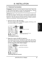
...ribbon cable. Pin 1 Orient the red stripe on the Pin 1 side of the ASUS Motherboard." External Connectors WARNING! Keyboard Connector (5-pin female) This motherboard accepts an AT Keyboard Connector Plug as shown here. P5A-B Keyboard Connector 2. IMPORTANT: Ribbon cables should always be less than 18in. (46cm...connect the two plugs on hard drives and some floppy drives. INSTALLATION 5. Pin 1 is removed to Pin 1 R R P5A-B Floppy Disk Drive Connector ASUS P5A-B User's Manual 25 III. Some pins are used for connectors or power sources. IDE ribbon cable must be connected with ...
...ribbon cable. Pin 1 Orient the red stripe on the Pin 1 side of the ASUS Motherboard." External Connectors WARNING! Keyboard Connector (5-pin female) This motherboard accepts an AT Keyboard Connector Plug as shown here. P5A-B Keyboard Connector 2. IMPORTANT: Ribbon cables should always be less than 18in. (46cm...connect the two plugs on hard drives and some floppy drives. INSTALLATION 5. Pin 1 is removed to Pin 1 R R P5A-B Floppy Disk Drive Connector ASUS P5A-B User's Manual 25 III. Some pins are used for connectors or power sources. IDE ribbon cable must be connected with ...
P5A-B User Manual
Page 27
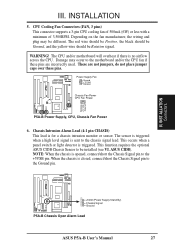
... These are incorrectly used. INST ALLATION Connectors R R +5Volt (Power Supply Stand By) Chassis Signal Ground P5A-B Chassis Open Alarm Lead ASUS P5A-B User's Manual 27 INSTALLATION 5. The CPU and/or motherboard will overheat if there is for a chassis intrusion monitor or sensor. Damage may be installed (see VI.... over these pins. Rotation +12 Volt Ground III. ASUS CIDB). This function requires the optional ASUS CIDB Chassis Sensor to the Ground pin. Power Supply Fan Ground +12 Volt Rotation Chassis Fan Power CPU Fan Power P5A-B Power Supply, CPU, Chassis Fan Power 6. The ...
... These are incorrectly used. INST ALLATION Connectors R R +5Volt (Power Supply Stand By) Chassis Signal Ground P5A-B Chassis Open Alarm Lead ASUS P5A-B User's Manual 27 INSTALLATION 5. The CPU and/or motherboard will overheat if there is for a chassis intrusion monitor or sensor. Damage may be installed (see VI.... over these pins. Rotation +12 Volt Ground III. ASUS CIDB). This function requires the optional ASUS CIDB Chassis Sensor to the Ground pin. Power Supply Fan Ground +12 Volt Rotation Chassis Fan Power CPU Fan Power P5A-B Power Supply, CPU, Chassis Fan Power 6. The ...


