

PSCH-SR User Manual English Version
Page 9
...® 82547GI CSA Gigabit LAN controller Intel® 82541GI Gigabit LAN controller (32-bit) ASUS unique features ASUS Q-Fan Technology ASUS Update (continued on the next page) ix PSCH-SR Series specifications summary CPU Chipset Socket 478 for Intel® Pentium™ 4 Prescott processors ...-channel memory architecture 4 x 184-pin DDR DIMM sockets for up to four UltraATA100/66/33 hard disk drives - 2 x Serial ATA connectors (for RAID 0 and RAID 1 configurations using two SATA hard disk drives and Windows® XP) Serial ATA model IDE model storage + Adaptec® AIC-8110X support...
...® 82547GI CSA Gigabit LAN controller Intel® 82541GI Gigabit LAN controller (32-bit) ASUS unique features ASUS Q-Fan Technology ASUS Update (continued on the next page) ix PSCH-SR Series specifications summary CPU Chipset Socket 478 for Intel® Pentium™ 4 Prescott processors ...-channel memory architecture 4 x 184-pin DDR DIMM sockets for up to four UltraATA100/66/33 hard disk drives - 2 x Serial ATA connectors (for RAID 0 and RAID 1 configurations using two SATA hard disk drives and Windows® XP) Serial ATA model IDE model storage + Adaptec® AIC-8110X support...
PSCH-SR User Manual English Version
Page 14
...or non-ECC DDR DIMMs to deliver up to 6.4 GB/s data transfer rate for two Serial ATA interfaces using Serial ATA150 hard disk drives or Ultra320 SCSI hard disk drives. For IDE models, the Intel® 6300ESB ICH provides RAID 0 and RAID 1 solution for various server applications. The ... surface mount ZIF socket. The processor with lower pin count, reduced voltage requirement, and up to 150 MB/s data transfer rate. The SATA specification allows for a multi-RAID solution using the Windows® XP operating system. Serial ATA technology The motherboard supports the new Serial ATA...
...or non-ECC DDR DIMMs to deliver up to 6.4 GB/s data transfer rate for two Serial ATA interfaces using Serial ATA150 hard disk drives or Ultra320 SCSI hard disk drives. For IDE models, the Intel® 6300ESB ICH provides RAID 0 and RAID 1 solution for various server applications. The ... surface mount ZIF socket. The processor with lower pin count, reduced voltage requirement, and up to 150 MB/s data transfer rate. The SATA specification allows for a multi-RAID solution using the Windows® XP operating system. Serial ATA technology The motherboard supports the new Serial ATA...
PSCH-SR User Manual English Version
Page 15
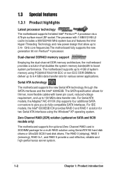
...the Universal Serial Bus (USB) 2.0 specification, dramatically increasing the connection speed from SCSI hard disk drives. This reduces the PCI bottlenecks by freeing the PCI bus for the ASUS server management card, managing your server motherboard has never been this easy. A chassis ...and Intel® 82547GI Gigabit Ethernet controller allows full-duplex Gigabit performance on LAN on the Memory Controller Hub (MCH). ASUS PSCH-SR motherboard user guide 1-3 Take the advantage of the Communication Streaming Architecture (CSA) with USB 1.1. Integrated graphics The onboard ATI...
...the Universal Serial Bus (USB) 2.0 specification, dramatically increasing the connection speed from SCSI hard disk drives. This reduces the PCI bottlenecks by freeing the PCI bus for the ASUS server management card, managing your server motherboard has never been this easy. A chassis ...and Intel® 82547GI Gigabit Ethernet controller allows full-duplex Gigabit performance on LAN on the Memory Controller Hub (MCH). ASUS PSCH-SR motherboard user guide 1-3 Take the advantage of the Communication Streaming Architecture (CSA) with USB 1.1. Integrated graphics The onboard ATI...
PSCH-SR User Manual English Version
Page 24
...], SEC_IDE1 [black) 2-25 6. Serial ATA RAID connectors (7-pin SATA_RAID1, 2-27 SATA_RAID2, SATA_RAID3, SATA_RAID4) 8. Locator connector (6-pin LOCATOR) 2-29 13. SATA/SCSI jumper controller (3-pin SASI_EN1) 2-18 5. USB 2.0 ports 1 and 2 7. Serial connector (10-1 pin COM2 for management use) 2-30 15....pin KBPWR1) 2-17 2. VGA port 5. Serial port 6. LAN LED connector (4-pin LAN_LED1) 2-27 9. Floppy disk drive connector (34-1 pin FLOPPY1) 2-28 11. Hard disk drive/SCSI LED switch (4-pin J4) 2-20 8. PS/2 mouse port 2. LAN2 port 4. CPU, Front, and Rear ...
...], SEC_IDE1 [black) 2-25 6. Serial ATA RAID connectors (7-pin SATA_RAID1, 2-27 SATA_RAID2, SATA_RAID3, SATA_RAID4) 8. Locator connector (6-pin LOCATOR) 2-29 13. SATA/SCSI jumper controller (3-pin SASI_EN1) 2-18 5. USB 2.0 ports 1 and 2 7. Serial connector (10-1 pin COM2 for management use) 2-30 15....pin KBPWR1) 2-17 2. VGA port 5. Serial port 6. LAN LED connector (4-pin LAN_LED1) 2-27 9. Floppy disk drive connector (34-1 pin FLOPPY1) 2-28 11. Hard disk drive/SCSI LED switch (4-pin J4) 2-20 8. PS/2 mouse port 2. LAN2 port 4. CPU, Front, and Rear ...
PSCH-SR User Manual English Version
Page 38
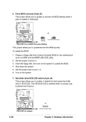
Set the jumper to update the BIOS. 4. Shut down the system. 5. Hard disk drive/SCSI LED switch (4-pin J4) This jumper allows you to update/recover the BIOS quickly. Insert the floppy disk, then turn on the system. 7. Prepare a ... BIOS Recovery Setting This jumper allows you to pins 1-2. 6. The HD/SCSI LED is enabled when no jumper cap is placed over the pins. ® PSCH-SR PSCH-SR J4 Jumper 2-20 J4 1 HD/SCSI LED Enable Chapter 2: Hardware information Turn on the system to pins 2-3. 3. 6. To update the BIOS: 1. Set the jumper back...
Set the jumper to update the BIOS. 4. Shut down the system. 5. Hard disk drive/SCSI LED switch (4-pin J4) This jumper allows you to update/recover the BIOS quickly. Insert the floppy disk, then turn on the system. 7. Prepare a ... BIOS Recovery Setting This jumper allows you to pins 1-2. 6. The HD/SCSI LED is enabled when no jumper cap is placed over the pins. ® PSCH-SR PSCH-SR J4 Jumper 2-20 J4 1 HD/SCSI LED Enable Chapter 2: Hardware information Turn on the system to pins 2-3. 3. 6. To update the BIOS: 1. Set the jumper back...

PSCH-SR User Manual English Version
Page 43
...connector. You may configure two hard disks to the hard disk documentation for the secondary IDE connector. • Pin 20 on each IDE connector is intentional. • For UltraATA IDE devices, use the 80-conductor IDE cable. ® PSCH-SR PSCH-SR IDE Connectors SEC_IDE1 PIN 1 ... prevents incorrect orientation when you connect non-UltraATA100 devices to the UltraATA100 master device. 5. ASUS PSCH-SR motherboard 2-25 If you install two hard disks, you must configure the second drive as a slave device by setting its jumper accordingly. Refer to be both master devices ...
...connector. You may configure two hard disks to the hard disk documentation for the secondary IDE connector. • Pin 20 on each IDE connector is intentional. • For UltraATA IDE devices, use the 80-conductor IDE cable. ® PSCH-SR PSCH-SR IDE Connectors SEC_IDE1 PIN 1 ... prevents incorrect orientation when you connect non-UltraATA100 devices to the UltraATA100 master device. 5. ASUS PSCH-SR motherboard 2-25 If you install two hard disks, you must configure the second drive as a slave device by setting its jumper accordingly. Refer to be both master devices ...
PSCH-SR User Manual English Version
Page 44
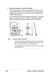
...hard disk drives and Windows® XP operating system, you can create a RAID 0 or RAID 1 configuration using the Serial ATA connectors will disable the Southbridge support to 150MB/s data transfer rate, faster than the standard parallel ATA with 133MB/s (Ultra ATA/133). GND RSATA_RXP2 RSATA_RXN2 GND RSATA_TXN2 RSATA_TXP2 GND ® PSCH-SR... SATA2 SATA1 GND RSATA_RXP1 RSATA_RXN1 GND RSATA_TXN1 RSATA_TXP1 GND PSCH-SR SATA Connectors Important notes on Serial ATA • In a legacy operating ...
...hard disk drives and Windows® XP operating system, you can create a RAID 0 or RAID 1 configuration using the Serial ATA connectors will disable the Southbridge support to 150MB/s data transfer rate, faster than the standard parallel ATA with 133MB/s (Ultra ATA/133). GND RSATA_RXP2 RSATA_RXN2 GND RSATA_TXN2 RSATA_TXP2 GND ® PSCH-SR... SATA2 SATA1 GND RSATA_RXP1 RSATA_RXN1 GND RSATA_TXN1 RSATA_TXP1 GND PSCH-SR SATA Connectors Important notes on Serial ATA • In a legacy operating ...
PSCH-SR User Manual English Version
Page 45
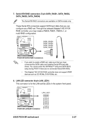
... GND PSCH-SR SATA RAID Connectors • If you wish to create a RAID set . LAN LED connector (4-pin LAN_LED1) This connector is for the LAN activity LEDs in the system front panel. ® PSCH-SR LAN_LED1 LAN1_LINKACTLED+ LAN1_LINKACTLEDLAN2_LINKACTLEDLAN2_LINKACTLED+ PSCH-SR LANLED Connector ASUS PSCH-SR motherboard ...you have connected the SATA cable and installed Serial ATA hard disk drives. You cannot enter the SATARaid™ utility and SATA BIOS setup during POST if there are available on SATA models only. These Serial ATA connectors support SATA hard disks that you can ...
... GND PSCH-SR SATA RAID Connectors • If you wish to create a RAID set . LAN LED connector (4-pin LAN_LED1) This connector is for the LAN activity LEDs in the system front panel. ® PSCH-SR LAN_LED1 LAN1_LINKACTLED+ LAN1_LINKACTLEDLAN2_LINKACTLEDLAN2_LINKACTLED+ PSCH-SR LANLED Connector ASUS PSCH-SR motherboard ...you have connected the SATA cable and installed Serial ATA hard disk drives. You cannot enter the SATARaid™ utility and SATA BIOS setup during POST if there are available on SATA models only. These Serial ATA connectors support SATA hard disks that you can ...
PSCH-SR User Manual English Version
Page 47
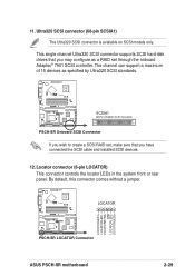
... on SCSI models only. This single channel Ultra320 SCSI connector supports SCSI hard disk drives that you may configure as specified by Ultra320 SCSI standards. ® PSCH-SR SCSIA1 68-Pin Ultra320 SCSI Connector 34 1 68 35 PSCH-SR Onboard SCSI Connector If you wish to create a SCSI RAID set, ... This connector controls the locator LEDs in the system front or rear panel. By default, this connector comes without a jumper. ® PSCH-SR LOCATOR LOCATORLED1+ LOCATORLED1LOCATORBTN#+ GND LOCATORLED2LOCATORLED2+ PSCH-SR LOCATOR Connector ASUS PSCH-SR motherboard 2-29 11.
... on SCSI models only. This single channel Ultra320 SCSI connector supports SCSI hard disk drives that you may configure as specified by Ultra320 SCSI standards. ® PSCH-SR SCSIA1 68-Pin Ultra320 SCSI Connector 34 1 68 35 PSCH-SR Onboard SCSI Connector If you wish to create a SCSI RAID set, ... This connector controls the locator LEDs in the system front or rear panel. By default, this connector comes without a jumper. ® PSCH-SR LOCATOR LOCATORLED1+ LOCATORLED1LOCATORBTN#+ GND LOCATORLED2LOCATORLED2+ PSCH-SR LOCATOR Connector ASUS PSCH-SR motherboard 2-29 11.
PSCH-SR User Manual English Version
Page 49
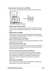
... of IDE connectors cause the hard disk drive LED to the hard disk drive LED. The LED blinks when the system is in sleep mode. • Message LED (2-pin MLED) This connector is for the system power LED. ASUS PSCH-SR motherboard 2-31 POWERLED+ NC POWERLEDMLED+ MLEDNC +5V GND GND SPKROUT ® PSCH-SR PANEL1 HDLED+ HDLEDNMIBTN# GND POWERBTN...
... of IDE connectors cause the hard disk drive LED to the hard disk drive LED. The LED blinks when the system is in sleep mode. • Message LED (2-pin MLED) This connector is for the system power LED. ASUS PSCH-SR motherboard 2-31 POWERLED+ NC POWERLEDMLED+ MLEDNC +5V GND GND SPKROUT ® PSCH-SR PANEL1 HDLED+ HDLEDNMIBTN# GND POWERBTN...
PSCH-SR User Manual English Version
Page 66
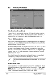
...options: [CHS] [LBA] [Large] [Auto] 4-10 Chapter 4: BIOS Setup appears as the BIOS attempts to automatically detect an IDE drive, if the drive is successful, the setup BIOS automatically fills in the correct values for the remaining fields on this item is set to [CHS] if... detected. Set this may detect incorrect parameters. Primary IDE Master [Auto] Select [Auto] to manually enter the IDE drive parameters. If automatic detection fails, this item to [Manual] so you can manually enter the drive values. Refer to [Auto]. Upon pressing , the message "Detecting Hard Drive..."
...options: [CHS] [LBA] [Large] [Auto] 4-10 Chapter 4: BIOS Setup appears as the BIOS attempts to automatically detect an IDE drive, if the drive is successful, the setup BIOS automatically fills in the correct values for the remaining fields on this item is set to [CHS] if... detected. Set this may detect incorrect parameters. Primary IDE Master [Auto] Select [Auto] to manually enter the IDE drive parameters. If automatic detection fails, this item to [Manual] so you can manually enter the drive values. Refer to [Auto]. Upon pressing , the message "Detecting Hard Drive..."
PSCH-SR User Manual English Version
Page 68
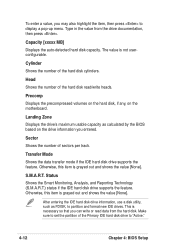
...grayed out and shows the value [None]. To enter a value, you can write or read /write heads. Type in the value from the hard disk. Landing Zone Displays the drive's maximum usable capacity as FDISK, to display a pop-up menu. Transfer Mode Shows the data transfer mode if the IDE...is necessary so that you may also highlight the item, then press to partition and format new IDE drives. Cylinder Shows the number of the Primary IDE hard disk drive to set the partition of the hard disk cylinders. Head Shows the number of sectors per track. Make sure to "Active." 4-12 Chapter...
...grayed out and shows the value [None]. To enter a value, you can write or read /write heads. Type in the value from the hard disk. Landing Zone Displays the drive's maximum usable capacity as FDISK, to display a pop-up menu. Transfer Mode Shows the data transfer mode if the IDE...is necessary so that you may also highlight the item, then press to partition and format new IDE drives. Cylinder Shows the number of the Primary IDE hard disk drive to set the partition of the hard disk cylinders. Head Shows the number of sectors per track. Make sure to "Active." 4-12 Chapter...
PSCH-SR User Manual English Version
Page 84
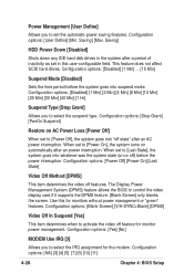
... IRQ assignment for monitors without power management or "green" features. Saving] HDD Power Down [Disabled] Shuts down any IDE hard disk drives in this for the modem. This feature does not affect SCSI hard drives. When set the automatic power saving features. Configuration options: [Yes] [No] MODEM Use IRQ [3] Allows you to [Power On...
... IRQ assignment for monitors without power management or "green" features. Saving] HDD Power Down [Disabled] Shuts down any IDE hard disk drives in this for the modem. This feature does not affect SCSI hard drives. When set the automatic power saving features. Configuration options: [Yes] [No] MODEM Use IRQ [3] Allows you to [Power On...