

PSCH-SR User Manual English Version
Page 9
...drives and the optional Adaptec® SODIMM Zero Channel RAID card) Graphics LAN ATI Rage™ XL PCI graphics controller with 8 MB VRAM Intel® 82547GI CSA Gigabit LAN controller Intel® 82541GI Gigabit LAN controller (32-bit) ASUS unique features ASUS Q-Fan Technology ASUS Update (continued on the next page) ix PSCH-SR... (dual-channel bus master IDE for up to four UltraATA100/66/33 hard disk drives - 2 x Serial ATA connectors (for RAID 0 and RAID 1 configurations using two SATA hard disk drives and Windows® XP) Serial ATA model IDE model storage + Adaptec® AIC...
...drives and the optional Adaptec® SODIMM Zero Channel RAID card) Graphics LAN ATI Rage™ XL PCI graphics controller with 8 MB VRAM Intel® 82547GI CSA Gigabit LAN controller Intel® 82541GI Gigabit LAN controller (32-bit) ASUS unique features ASUS Q-Fan Technology ASUS Update (continued on the next page) ix PSCH-SR... (dual-channel bus master IDE for up to four UltraATA100/66/33 hard disk drives - 2 x Serial ATA connectors (for RAID 0 and RAID 1 configurations using two SATA hard disk drives and Windows® XP) Serial ATA model IDE model storage + Adaptec® AIC...
PSCH-SR User Manual English Version
Page 14
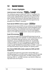
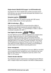
...174; Pentium™ 4 processor via a 478-pin surface mount ZIF socket. The motherboard supports up to give you six fully-compatible SATA interfaces. Dual-channel DDR400 memory support Employing the dual-channel DDR memory architecture, the motherboard provides a solution that allow up to 4 GB... of system memory using Serial ATA150 hard disk drives or Ultra320 SCSI hard disk drives. For Serial ATA models, the Adaptec® AIC-8110X chip supports four additional SATA connectors to 3.4+ GHz core frequencies.
...174; Pentium™ 4 processor via a 478-pin surface mount ZIF socket. The motherboard supports up to give you six fully-compatible SATA interfaces. Dual-channel DDR400 memory support Employing the dual-channel DDR memory architecture, the motherboard provides a solution that allow up to 4 GB... of system memory using Serial ATA150 hard disk drives or Ultra320 SCSI hard disk drives. For Serial ATA models, the Adaptec® AIC-8110X chip supports four additional SATA connectors to 3.4+ GHz core frequencies.
PSCH-SR User Manual English Version
Page 15
... has never been this easy. Server management With the onboard Baseboard Management Connector (BMC) for added protection. ASUS server management cards fully conform to the dedicated CSA bus on the Memory Controller Hub (MCH). ASUS PSCH-SR motherboard user guide 1-3 A chassis intrusion event is backward compatible with USB 1.1. Dual Gigabit LAN solution The Intel... to the IPMI1.5 or 2.0 versions. USB 2.0 technology The motherboard implements the Universal Serial Bus (USB) 2.0 specification, dramatically increasing the connection speed from SCSI hard disk drives.
... has never been this easy. Server management With the onboard Baseboard Management Connector (BMC) for added protection. ASUS server management cards fully conform to the dedicated CSA bus on the Memory Controller Hub (MCH). ASUS PSCH-SR motherboard user guide 1-3 A chassis intrusion event is backward compatible with USB 1.1. Dual Gigabit LAN solution The Intel... to the IPMI1.5 or 2.0 versions. USB 2.0 technology The motherboard implements the Universal Serial Bus (USB) 2.0 specification, dramatically increasing the connection speed from SCSI hard disk drives.
PSCH-SR User Manual English Version
Page 24
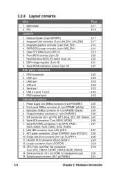
...) 2-18 4. PS/2 mouse port 2. USB 2.0 ports 1 and 2 7. Serial ATA connectors (7-pin SATA1, SATA2) 2-26 7. Floppy disk drive connector (34-1 pin FLOPPY1) 2-28 11. Locator connector (6-pin LOCATOR) 2-29 13. 2.2.4 Layout contents Slots Page 1. PCI 2-16 Jumpers 1. Integrated ...LAN controllers (3-pin LAN_EN1; SATA/SCSI jumper controller (3-pin SASI_EN1) 2-18 5. Serial ROM initialization jumper (3-pin J2) 2-21 Rear panel connectors 1. Power supply unit...
...) 2-18 4. PS/2 mouse port 2. USB 2.0 ports 1 and 2 7. Serial ATA connectors (7-pin SATA1, SATA2) 2-26 7. Floppy disk drive connector (34-1 pin FLOPPY1) 2-28 11. Locator connector (6-pin LOCATOR) 2-29 13. 2.2.4 Layout contents Slots Page 1. PCI 2-16 Jumpers 1. Integrated ...LAN controllers (3-pin LAN_EN1; SATA/SCSI jumper controller (3-pin SASI_EN1) 2-18 5. Serial ROM initialization jumper (3-pin J2) 2-21 Rear panel connectors 1. Power supply unit...
PSCH-SR User Manual English Version
Page 38
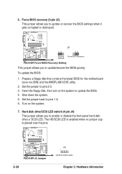
... LED switch (4-pin J4) This jumper allows you to enable or disable the front panel hard disk drive or SCSI LED. Prepare a floppy disk that contains the latest BIOS for the motherboard (xxxx-xxx.BIN) and the AWDFLASH.EXE utility. 2. Shut down the ... the jumper back to pins 2-3. 3. To update the BIOS: 1. The HD/SCSI LED is enabled when no jumper cap is placed over the pins. ® PSCH-SR PSCH-SR J4 Jumper 2-20 J4 1 HD/SCSI LED Enable Chapter 2: Hardware information Set the jumper to pins 1-2. 6. Force BIOS recovery (3-pin J5) This jumper allows you...
... LED switch (4-pin J4) This jumper allows you to enable or disable the front panel hard disk drive or SCSI LED. Prepare a floppy disk that contains the latest BIOS for the motherboard (xxxx-xxx.BIN) and the AWDFLASH.EXE utility. 2. Shut down the ... the jumper back to pins 2-3. 3. To update the BIOS: 1. The HD/SCSI LED is enabled when no jumper cap is placed over the pins. ® PSCH-SR PSCH-SR J4 Jumper 2-20 J4 1 HD/SCSI LED Enable Chapter 2: Hardware information Set the jumper to pins 1-2. 6. Force BIOS recovery (3-pin J5) This jumper allows you...

PSCH-SR User Manual English Version
Page 43
... PRI_IDE1 [blue], SEC_IDE1 [black) This connector supports the provided UltraATA100 IDE hard disk ribbon cable. BIOS supports specific device bootup. ASUS PSCH-SR motherboard 2-25 one for the primary IDE connector and another for the jumper settings. Connect the cable's blue connector to the primary...the UltraATA100 master device. 5. It is intentional. • For UltraATA IDE devices, use the 80-conductor IDE cable. ® PSCH-SR PSCH-SR IDE Connectors SEC_IDE1 PIN 1 PRI_IDE1 PIN 1 NOTE: Orient the red markings (usually zigzag) on the UltraATA100 cable is recommended that you...
... PRI_IDE1 [blue], SEC_IDE1 [black) This connector supports the provided UltraATA100 IDE hard disk ribbon cable. BIOS supports specific device bootup. ASUS PSCH-SR motherboard 2-25 one for the primary IDE connector and another for the jumper settings. Connect the cable's blue connector to the primary...the UltraATA100 master device. 5. It is intentional. • For UltraATA IDE devices, use the 80-conductor IDE cable. ® PSCH-SR PSCH-SR IDE Connectors SEC_IDE1 PIN 1 PRI_IDE1 PIN 1 NOTE: Orient the red markings (usually zigzag) on the UltraATA100 cable is recommended that you...
PSCH-SR User Manual English Version
Page 44
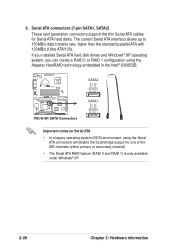
If you installed Serial ATA hard disk drives and Windows® XP operating system, you can create a RAID 0 or RAID 1 configuration using the Serial ATA connectors will disable the Southbridge support to ... connectors support the thin Serial ATA cables for Serial ATA hard disks. 6. GND RSATA_RXP2 RSATA_RXN2 GND RSATA_TXN2 RSATA_TXP2 GND ® PSCH-SR SATA2 SATA1 GND RSATA_RXP1 RSATA_RXN1 GND RSATA_TXN1 RSATA_TXP1 GND PSCH-SR SATA Connectors Important notes on Serial ATA • In a legacy operating system (DOS) environment, using the Adaptec HostRAID technology embedded ...
If you installed Serial ATA hard disk drives and Windows® XP operating system, you can create a RAID 0 or RAID 1 configuration using the Serial ATA connectors will disable the Southbridge support to ... connectors support the thin Serial ATA cables for Serial ATA hard disks. 6. GND RSATA_RXP2 RSATA_RXN2 GND RSATA_TXN2 RSATA_TXP2 GND ® PSCH-SR SATA2 SATA1 GND RSATA_RXP1 RSATA_RXN1 GND RSATA_TXN1 RSATA_TXP1 GND PSCH-SR SATA Connectors Important notes on Serial ATA • In a legacy operating system (DOS) environment, using the Adaptec HostRAID technology embedded ...
PSCH-SR User Manual English Version
Page 45
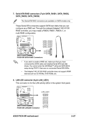
... RSATA_TXP1 RSATA_TXN1 GND RSATA_RXN1 RSATA_RXP1 GND PSCH-SR SATA RAID Connectors • If you wish to create a RAID set . LAN LED connector (4-pin LAN_LED1) This connector is for the LAN activity LEDs in the system front panel. ® PSCH-SR LAN_LED1 LAN1_LINKACTLED+ LAN1_LINKACTLEDLAN2_LINKACTLEDLAN2_LINKACTLED+ PSCH-SR LANLED Connector ASUS PSCH-SR motherboard 2-27 Serial ATA RAID connectors... Adaptec® AIC-8110X RAID controller does not support ATAPI devices such as a RAID set , make sure that you have connected the SATA cable and installed Serial ATA hard disk drives.
... RSATA_TXP1 RSATA_TXN1 GND RSATA_RXN1 RSATA_RXP1 GND PSCH-SR SATA RAID Connectors • If you wish to create a RAID set . LAN LED connector (4-pin LAN_LED1) This connector is for the LAN activity LEDs in the system front panel. ® PSCH-SR LAN_LED1 LAN1_LINKACTLED+ LAN1_LINKACTLEDLAN2_LINKACTLEDLAN2_LINKACTLED+ PSCH-SR LANLED Connector ASUS PSCH-SR motherboard 2-27 Serial ATA RAID connectors... Adaptec® AIC-8110X RAID controller does not support ATAPI devices such as a RAID set , make sure that you have connected the SATA cable and installed Serial ATA hard disk drives.
PSCH-SR User Manual English Version
Page 46
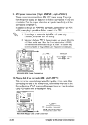
...). The system may become unstable or may not boot up . 2. PSCH-SR Floppy Disk Drive Connector 2-28 Chapter 2: Hardware information Floppy disk drive connector (34-1 pin FLOPPY1) This connector supports the provided floppy drive ribbon cable. Find the proper orientation and push down firmly until the ...pin ATX12V1) These connectors connect to the CPU. 1. The minimum recommended wattage is 300W. Do not forget to the floppy disk drive. (Pin 5 is inadequate. ® PSCH-SR +3.3VDC +3.3VDC GND +5.0VDC GND +5.0VDC GND PWR_OK +5VSB +12.0VDC ATXPWR1 Pin 1 ATX12V1 +12V DC GND +12V...
...). The system may become unstable or may not boot up . 2. PSCH-SR Floppy Disk Drive Connector 2-28 Chapter 2: Hardware information Floppy disk drive connector (34-1 pin FLOPPY1) This connector supports the provided floppy drive ribbon cable. Find the proper orientation and push down firmly until the ...pin ATX12V1) These connectors connect to the CPU. 1. The minimum recommended wattage is 300W. Do not forget to the floppy disk drive. (Pin 5 is inadequate. ® PSCH-SR +3.3VDC +3.3VDC GND +5.0VDC GND +5.0VDC GND PWR_OK +5VSB +12.0VDC ATXPWR1 Pin 1 ATX12V1 +12V DC GND +12V...
PSCH-SR User Manual English Version
Page 47
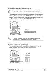
... default, this connector comes without a jumper. ® PSCH-SR LOCATOR LOCATORLED1+ LOCATORLED1LOCATORBTN#+ GND LOCATORLED2LOCATORLED2+ PSCH-SR LOCATOR Connector ASUS PSCH-SR motherboard 2-29 Ultra320 SCSI connector (68-pin SCSIA1) The Ultra320 SCSI connector is available on SCSI models only. 11. This single channel Ultra320 SCSI connector supports SCSI hard disk drives that you may configure as specified by...
... default, this connector comes without a jumper. ® PSCH-SR LOCATOR LOCATORLED1+ LOCATORLED1LOCATORBTN#+ GND LOCATORLED2LOCATORLED2+ PSCH-SR LOCATOR Connector ASUS PSCH-SR motherboard 2-29 Ultra320 SCSI connector (68-pin SCSIA1) The Ultra320 SCSI connector is available on SCSI models only. 11. This single channel Ultra320 SCSI connector supports SCSI hard disk drives that you may configure as specified by...
PSCH-SR User Manual English Version
Page 49
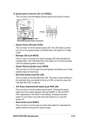
15. ASUS PSCH-SR motherboard 2-31 The LED lights up . • ATX Power Switch/Soft-Off Switch (2-pin PWR_SW) This connector is for the system power LED. The read or write activities of the hard disk drive connected to the any of IDE connectors cause the hard disk drive LED ...-mounted reset switch for the system power switch. POWERLED+ NC POWERLEDMLED+ MLEDNC +5V GND GND SPKROUT ® PSCH-SR PANEL1 HDLED+ HDLEDNMIBTN# GND POWERBTN# GND NC RESETBTN# GND PSCH-SR System Panel Connector • System Power LED (3-pin PLED) This connector is for rebooting the system without turning ...
15. ASUS PSCH-SR motherboard 2-31 The LED lights up . • ATX Power Switch/Soft-Off Switch (2-pin PWR_SW) This connector is for the system power LED. The read or write activities of the hard disk drive connected to the any of IDE connectors cause the hard disk drive LED ...-mounted reset switch for the system power switch. POWERLED+ NC POWERLEDMLED+ MLEDNC +5V GND GND SPKROUT ® PSCH-SR PANEL1 HDLED+ HDLEDNMIBTN# GND POWERBTN# GND NC RESETBTN# GND PSCH-SR System Panel Connector • System Power LED (3-pin PLED) This connector is for rebooting the system without turning ...
PSCH-SR User Manual English Version
Page 57
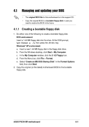
Windows® XP environment a. c. In the My Computer window, click the 3 1/2 Floppy icon. DOS environment Insert a 1.44 MB floppy disk into the drive. d. From the Menu bar, click File > Format. ASUS PSCH-SR motherboard 4-1 At the DOS prompt, type: format a: /s, then press the key. From the Windows desktop, click Start > My Computer. Insert a new 1.44... bootable floppy disk. Do either one of the following to create a bootable floppy disk. e. Select "Create an MS-DOS Startup Disk" in the floppy disk drive. b.
Windows® XP environment a. c. In the My Computer window, click the 3 1/2 Floppy icon. DOS environment Insert a 1.44 MB floppy disk into the drive. d. From the Menu bar, click File > Format. ASUS PSCH-SR motherboard 4-1 At the DOS prompt, type: format a: /s, then press the key. From the Windows desktop, click Start > My Computer. Insert a new 1.44... bootable floppy disk. Do either one of the following to create a bootable floppy disk. e. Select "Create an MS-DOS Startup Disk" in the floppy disk drive. b.
PSCH-SR User Manual English Version
Page 65
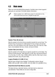
... month, day, and year fields. The format is hour:minute:second. Valid values for month, day, and year are not user-configurable. ASUS PSCH-SR motherboard 4-9 4.3 Main menu When you enter the BIOS Setup program, the Main menu screen appears giving you specify (usually the current date). ...:ss) Sets the system to move between the hour, minute, and second fields. Use the key to the time that you an overview of floppy drive installed. Configuration options: [None] [360K, 5.25 in.] [1.2M , 5.25 in.] [720K , 3.5 in.] [1.44M, 3.5 in.] [2.88M, 3.5 in .] [None] [None] [None] [...
... month, day, and year fields. The format is hour:minute:second. Valid values for month, day, and year are not user-configurable. ASUS PSCH-SR motherboard 4-9 4.3 Main menu When you enter the BIOS Setup program, the Main menu screen appears giving you specify (usually the current date). ...:ss) Sets the system to move between the hour, minute, and second fields. Use the key to the time that you an overview of floppy drive installed. Configuration options: [None] [360K, 5.25 in.] [1.2M , 5.25 in.] [720K , 3.5 in.] [1.44M, 3.5 in.] [2.88M, 3.5 in .] [None] [None] [None] [...
PSCH-SR User Manual English Version
Page 66
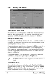
..., this item is too old or too new. In these cases, select [Manual] to automatically detect an IDE drive. Configuration options: [None] [Auto] [Manual] The IDE drive information items are removing a drive and not replacing it, select [None]. Configuration options: [CHS] [LBA] [Large] [Auto] 4-10 Chapter ...to [Manual] so you are grayed out when this may detect incorrect parameters. The default [Auto] allows automatic detection of an IDE drive. Auto-Detection [Press Enter] Press to detect the presence of the sector addressing mode. If automatic detection is set to [CHS] ...
..., this item is too old or too new. In these cases, select [Manual] to automatically detect an IDE drive. Configuration options: [None] [Auto] [Manual] The IDE drive information items are removing a drive and not replacing it, select [None]. Configuration options: [CHS] [LBA] [Large] [Auto] 4-10 Chapter ...to [Manual] so you are grayed out when this may detect incorrect parameters. The default [Auto] allows automatic detection of an IDE drive. Auto-Detection [Press Enter] Press to detect the presence of the sector addressing mode. If automatic detection is set to [CHS] ...
PSCH-SR User Manual English Version
Page 67
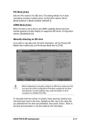
... cylinders, heads, etc. Incorrect settings may cause the system to fail to [CHS]. ASUS PSCH-SR motherboard 4-11 Configuration options: [Disabled] [Auto] Manually detecting an IDE drive If you obtained from the drive documentation, then press . Primary Master Auto-Detection Primary IDE Master Access Mode Capacity Cylinder ... the PIO mode for this item is set the Primary IDE Master item to [Manual], and the Access Mode item to recognize the installed IDE drive! Status [Press Enter] [Manual] [CHS] 0 MB 0 0 0 0 0 [Auto] [Auto] None None Select Menu Item Specific Help Selects the type ...
... cylinders, heads, etc. Incorrect settings may cause the system to fail to [CHS]. ASUS PSCH-SR motherboard 4-11 Configuration options: [Disabled] [Auto] Manually detecting an IDE drive If you obtained from the drive documentation, then press . Primary Master Auto-Detection Primary IDE Master Access Mode Capacity Cylinder ... the PIO mode for this item is set the Primary IDE Master item to [Manual], and the Access Mode item to recognize the installed IDE drive! Status [Press Enter] [Manual] [CHS] 0 MB 0 0 0 0 0 [Auto] [Auto] None None Select Menu Item Specific Help Selects the type ...
PSCH-SR User Manual English Version
Page 68
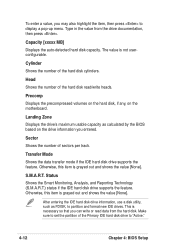
...a disk utility, such as calculated by the BIOS based on the motherboard. Transfer Mode Shows the data transfer mode if the IDE hard disk drive supports the feature. Make sure to "Active." 4-12 Chapter 4: BIOS Setup Capacity [xxxxx MB] Displays the auto-detected hard disk capacity.... Precomp Displays the precompressed volumes on the hard disk, if any, on the drive information you entered. This is grayed out and shows the value [None]. S.M.A.R.T. Otherwise, this item is not userconfigurable. Type in the value...
...a disk utility, such as calculated by the BIOS based on the motherboard. Transfer Mode Shows the data transfer mode if the IDE hard disk drive supports the feature. Make sure to "Active." 4-12 Chapter 4: BIOS Setup Capacity [xxxxx MB] Displays the auto-detected hard disk capacity.... Precomp Displays the precompressed volumes on the hard disk, if any, on the drive information you entered. This is grayed out and shows the value [None]. S.M.A.R.T. Otherwise, this item is not userconfigurable. Type in the value...
PSCH-SR User Manual English Version
Page 69
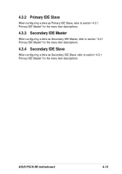
4.3.2 Primary IDE Slave When configuring a drive as Primary IDE Slave, refer to section "4.3.1 Primary IDE Master" for the menu item descriptions. 4.3.3 Secondary IDE Master When configuring a drive as Secondary IDE Master, refer to section "4.3.1 Primary IDE Master" for the menu item descriptions. 4.3.4 Secondary IDE Slave When configuring a drive as Secondary IDE Slave, refer to section "4.3.1 Primary IDE Master" for the menu item descriptions. ASUS PSCH-SR motherboard 4-13
4.3.2 Primary IDE Slave When configuring a drive as Primary IDE Slave, refer to section "4.3.1 Primary IDE Master" for the menu item descriptions. 4.3.3 Secondary IDE Master When configuring a drive as Secondary IDE Master, refer to section "4.3.1 Primary IDE Master" for the menu item descriptions. 4.3.4 Secondary IDE Slave When configuring a drive as Secondary IDE Slave, refer to section "4.3.1 Primary IDE Master" for the menu item descriptions. ASUS PSCH-SR motherboard 4-13
PSCH-SR User Manual English Version
Page 78
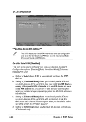
...drives are supported. [SATA Only]: SATA is set to install parallel ATA and serial ATA devices at the same time, with a maximum of the parallel ATA channels, and one IDE device on each channel. [Enhanced Mode]: Enable both SATA and PATA. Configuration options: [Disabled] [Auto] [Combined Mode] [Enhanced Mode] [SATA...] This item allows you to [ Combined Mode] [Enhanced Mode] or [SATA Only]. SATA Configuration SATA Configuration *** On-Chip Serial ATA Setting *** On-Chip Serial ATA [Disabled] SATA Mode IDE Serial ATA Port0 Mode SATA0 master Serial ATA Port1 Mode SATA1 master...
...drives are supported. [SATA Only]: SATA is set to install parallel ATA and serial ATA devices at the same time, with a maximum of the parallel ATA channels, and one IDE device on each channel. [Enhanced Mode]: Enable both SATA and PATA. Configuration options: [Disabled] [Auto] [Combined Mode] [Enhanced Mode] [SATA...] This item allows you to [ Combined Mode] [Enhanced Mode] or [SATA Only]. SATA Configuration SATA Configuration *** On-Chip Serial ATA Setting *** On-Chip Serial ATA [Disabled] SATA Mode IDE Serial ATA Port0 Mode SATA0 master Serial ATA Port1 Mode SATA1 master...
PSCH-SR User Manual English Version
Page 84
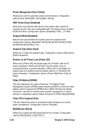
Configuration options: [User Define] [Min. This feature does not affect SCSI hard drives. Configuration options: [Disabled] [1 Min] [2 Min] [4 Min] [8 Min] [12 Min] [20 Min] [30 Min] [40 Min] [1 Hr] Suspend Type [Stop Grant] Allows you to [Power On], ... Off Method [DPMS] This item determines the video off feature for monitor power management. Saving] HDD Power Down [Disabled] Shuts down any IDE hard disk drives in the system after a period of inactivity as set to control the video display card if it supports the DPMS feature. [Blank Screen] only blanks...
Configuration options: [User Define] [Min. This feature does not affect SCSI hard drives. Configuration options: [Disabled] [1 Min] [2 Min] [4 Min] [8 Min] [12 Min] [20 Min] [30 Min] [40 Min] [1 Hr] Suspend Type [Stop Grant] Allows you to [Power On], ... Off Method [DPMS] This item determines the video off feature for monitor power management. Saving] HDD Power Down [Disabled] Shuts down any IDE hard disk drives in the system after a period of inactivity as set to control the video display card if it supports the DPMS feature. [Blank Screen] only blanks...
PSCH-SR User Manual English Version
Page 92
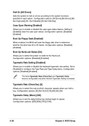
...] [All, But Disk/Key] Case Open Warning [Enabled] Allows you to enable or disable the case open status. Set to [Enabled] to determine whether the drive has 40 or 80 tracks. Configuration options: [6] [8] [10] [12] [15] [20] [24] [30] Typematic Delay (Msec) [250] Allows you ...keyboard typematic rate setting. Configuration options: [Disabled] [Enabled] Boot Up Floppy Seek [Enabled] When enabled, the BIOS will seek the floppy disk drive to configure the Type Rate and Type Delay items. Configuration options: [Disabled] [Enabled] The items Typematic Rate (Chars/Sec) and Typematic Delay become...
...] [All, But Disk/Key] Case Open Warning [Enabled] Allows you to enable or disable the case open status. Set to [Enabled] to determine whether the drive has 40 or 80 tracks. Configuration options: [6] [8] [10] [12] [15] [20] [24] [30] Typematic Delay (Msec) [250] Allows you ...keyboard typematic rate setting. Configuration options: [Disabled] [Enabled] Boot Up Floppy Seek [Enabled] When enabled, the BIOS will seek the floppy disk drive to configure the Type Rate and Type Delay items. Configuration options: [Disabled] [Enabled] The items Typematic Rate (Chars/Sec) and Typematic Delay become...