

User Manual
Page 1
R TX97 Pentium Motherboard USER'S MANUAL
R TX97 Pentium Motherboard USER'S MANUAL

User Manual
Page 2
... or by any means, except documentation kept by the digit before and after the period of the manual revision number. Product Name: ASUS TX97 Manual Revision: 1.23 Release Date: August 1997 2 ASUS TX97 User's Manual SPECIFICATIONS AND INFORMATION CONTAINED IN THIS MANUAL ARE FURNISHED FOR INFORMATIONAL USE ONLY, AND ARE SUBJECT TO CHANGE AT ANY TIME WITHOUT NOTICE...
... or by any means, except documentation kept by the digit before and after the period of the manual revision number. Product Name: ASUS TX97 Manual Revision: 1.23 Release Date: August 1997 2 ASUS TX97 User's Manual SPECIFICATIONS AND INFORMATION CONTAINED IN THIS MANUAL ARE FURNISHED FOR INFORMATIONAL USE ONLY, AND ARE SUBJECT TO CHANGE AT ANY TIME WITHOUT NOTICE...

User Manual
Page 3
...Technical Support Fax: +886-2-895-9254 BBS: +886-2-896-4667 Email: tsd@asus.com.tw WWW: www.asus.com.tw Gopher: gopher.asus.com.tw FTP: ftp.asus.com.tw/pub/ASUS ASUS COMPUTER INTERNATIONAL Marketing Info Address: 721 Charcot Avenue, San Jose, CA 95131, ...asus.com.tw WWW: www.asus.com ASUS COMPUTER GmbH Marketing Info Address: Harkort Str. 25, 40880 Ratingen, BRD, Germany Telephone: 49-2102-445011 Fax: 49-2102-442066 Email: info-ger@asus.com.tw Technical Support BBS: 49-2102-448690 Email: tsd-ger@asus.com.tw Hotline: 49-2102-499712 ASUS TX97 User's Manual 3 ASUS...
...Technical Support Fax: +886-2-895-9254 BBS: +886-2-896-4667 Email: tsd@asus.com.tw WWW: www.asus.com.tw Gopher: gopher.asus.com.tw FTP: ftp.asus.com.tw/pub/ASUS ASUS COMPUTER INTERNATIONAL Marketing Info Address: 721 Charcot Avenue, San Jose, CA 95131, ...asus.com.tw WWW: www.asus.com ASUS COMPUTER GmbH Marketing Info Address: Harkort Str. 25, 40880 Ratingen, BRD, Germany Telephone: 49-2102-445011 Fax: 49-2102-442066 Email: info-ger@asus.com.tw Technical Support BBS: 49-2102-448690 Email: tsd-ger@asus.com.tw Hotline: 49-2102-499712 ASUS TX97 User's Manual 3 ASUS...
User Manual
Page 4
... of BIOS Features Setup 39 Chipset Features Setup 42 Details of Chipset Features Setup 42 Power Management Setup 45 Details of Power Management Setup 45 4 ASUS TX97 User's Manual External Connectors 24 Power Connection Procedures 31 IV. System Memory (DIMM 19 DIMM Memory Installation Procedures 20 3.
... of BIOS Features Setup 39 Chipset Features Setup 42 Details of Chipset Features Setup 42 Power Management Setup 45 Details of Power Management Setup 45 4 ASUS TX97 User's Manual External Connectors 24 Power Connection Procedures 31 IV. System Memory (DIMM 19 DIMM Memory Installation Procedures 20 3.

User Manual
Page 5
...-SC200 60 Terminator Requirements for SCSI Devices 60 Terminator Settings for the ASUS PCI-SC860 61 Terminator Settings for the ASUS PCI-SC200 61 SCSI ID Numbers for SCSI Devices 62 SCSI ID Priority 62 ASUS TX97 User's Manual 5 SUPPORT SOFTWARE 54 ASUS TX97 Motherboard Series Support CD 54 LANDesk Client Manager (LDCM 54 Desktop Management Interface...
...-SC200 60 Terminator Requirements for SCSI Devices 60 Terminator Settings for the ASUS PCI-SC860 61 Terminator Settings for the ASUS PCI-SC200 61 SCSI ID Numbers for SCSI Devices 62 SCSI ID Priority 62 ASUS TX97 User's Manual 5 SUPPORT SOFTWARE 54 ASUS TX97 Motherboard Series Support CD 54 LANDesk Client Manager (LDCM 54 Desktop Management Interface...

User Manual
Page 6
... correct the interference by the party responsible for radio noise emissions from that to this unit not expressly approved by one or more of Communications. 6 ASUS TX97 User's Manual
... correct the interference by the party responsible for radio noise emissions from that to this unit not expressly approved by one or more of Communications. 6 ASUS TX97 User's Manual

User Manual
Page 7
... bracket set (optional) ATX to AT Power Connector Adapter (optional) ASUS PCI-SC200 Fast-SCSI or PCI-SC860 Ultra-Fast SCSI card (optional) ASUS TX97 User's Manual 7 Introduction: Manual information and checklist II. BIOS Software: Instructions on the included support software VI. I . INTRODUCTION (Manual / Checklist) I . The ASUS TX97 motherboard 2 serial port ribbon cables attached to a mounting bracket 1 parallel...
... bracket set (optional) ATX to AT Power Connector Adapter (optional) ASUS PCI-SC200 Fast-SCSI or PCI-SC860 Ultra-Fast SCSI card (optional) ASUS TX97 User's Manual 7 Introduction: Manual information and checklist II. BIOS Software: Instructions on the included support software VI. I . INTRODUCTION (Manual / Checklist) I . The ASUS TX97 motherboard 2 serial port ribbon cables attached to a mounting bracket 1 parallel...

User Manual
Page 8
...directed from COM2 to the Infrared Module for an optional high-performance expansion card which allows hardware to support optional ASUS SCSI controller cards. 8 ASUS TX97 User's Manual FEATURES Features of compatibility. (Requires DMI-enabled components.) (See section V) • PCI Bus Master IDE Controller... power adapter. • SCSI BIOS: Has firmware to communicate within a standard protocol creating a higher level of the ASUS TX97 Motherboard The ASUS TX97 is available for the demanding PC user who wants many intelligent features in a small package. BIOS now supports IDE CD...
...directed from COM2 to the Infrared Module for an optional high-performance expansion card which allows hardware to support optional ASUS SCSI controller cards. 8 ASUS TX97 User's Manual FEATURES Features of compatibility. (Requires DMI-enabled components.) (See section V) • PCI Bus Master IDE Controller... power adapter. • SCSI BIOS: Has firmware to communicate within a standard protocol creating a higher level of the ASUS TX97 Motherboard The ASUS TX97 is available for the demanding PC user who wants many intelligent features in a small package. BIOS now supports IDE CD...

User Manual
Page 9
... operating at a safe heat level to CPU. • ACPI Ready - With these features implemented in the next release of motherboards meet PC '97 compliancy. ASUS TX97 User's Manual 9 port the new generation memory - Concurrent PCI allows multiple PCI transfers from 264MB/s max using Bus Master UltraDMA/33 IDE which increases the data transfer...
... operating at a safe heat level to CPU. • ACPI Ready - With these features implemented in the next release of motherboards meet PC '97 compliancy. ASUS TX97 User's Manual 9 port the new generation memory - Concurrent PCI allows multiple PCI transfers from 264MB/s max using Bus Master UltraDMA/33 IDE which increases the data transfer...

User Manual
Page 10
...8226; Auto Fan Off - This function reduces both energy consumption and system noise, and is a important feature to the user. 10 ASUS TX97 User's Manual Pushing the power button for future processors, so monitoring is completed upon detection of system overheat. Through the way a particular LED illuminates,...disable write permission when the system's initialization stage is necessary to ensure proper system configuration and management. • System Resources Alert - ASUS TX97 series of two states, one is Sleep mode and the other is in the world! • Message LED - The system ...
...8226; Auto Fan Off - This function reduces both energy consumption and system noise, and is a important feature to the user. 10 ASUS TX97 User's Manual Pushing the power button for future processors, so monitoring is completed upon detection of system overheat. Through the way a particular LED illuminates,...disable write permission when the system's initialization stage is necessary to ensure proper system configuration and management. • System Resources Alert - ASUS TX97 series of two states, one is Sleep mode and the other is in the world! • Message LED - The system ...

User Manual
Page 11
FEATURES Parts of Board) PCI 4 or ASUS MediaBus 3 DIMM Sockets Programmable Flash ROM Intel's 430TX PCIset Hardware Monitor CPU Thermal Sensor CPU ZIF Socket 7 512KB Pipelined Burst L2 Cache Switching Voltage Regulators ASUS TX97 User's Manual 11 FEATURES (Parts of the ASUS TX97 Motherboard Super Multi-I/O 4 ISA Slots 3 PCI Slots IDE / Floppy Connectors PS/2 Mouse, USB, IrDA Parallel & Serial Ports II. II.
FEATURES Parts of Board) PCI 4 or ASUS MediaBus 3 DIMM Sockets Programmable Flash ROM Intel's 430TX PCIset Hardware Monitor CPU Thermal Sensor CPU ZIF Socket 7 512KB Pipelined Burst L2 Cache Switching Voltage Regulators ASUS TX97 User's Manual 11 FEATURES (Parts of the ASUS TX97 Motherboard Super Multi-I/O 4 ISA Slots 3 PCI Slots IDE / Floppy Connectors PS/2 Mouse, USB, IrDA Parallel & Serial Ports II. II.

User Manual
Page 12
INSTALLATION (Map of the ASUS TX97 Motherboard Super Multi-I/O PS/2 Mouse, USB, IrDA Keyboard Serial Ports COM 1 COM 2 Parallel (Printer) Port P8 P9 Power Fan Board Power Input ATX Power Switch ... Freq. III. Ratio CPU Fan Vcore Voltage Infrared Switching Voltage Regulators CPU ZIF Socket 7 Heat Sensor Intel 430TX PCIset 512KB Pipelined Burst L2 Cache 12 ASUS TX97 User's Manual
INSTALLATION (Map of the ASUS TX97 Motherboard Super Multi-I/O PS/2 Mouse, USB, IrDA Keyboard Serial Ports COM 1 COM 2 Parallel (Printer) Port P8 P9 Power Fan Board Power Input ATX Power Switch ... Freq. III. Ratio CPU Fan Vcore Voltage Infrared Switching Voltage Regulators CPU ZIF Socket 7 Heat Sensor Intel 430TX PCIset 512KB Pipelined Burst L2 Cache 12 ASUS TX97 User's Manual

User Manual
Page 13
... Lead (5-pins) p. 29 Speaker Output Connector (4-pins) p. 30 PS/2 Mouse/USB/IR Combo-Connector (18-pin Block) p. 30 Second Infrared Port Module Connector (5-pin Block) ASUS TX97 User's Manual 13 III.
... Lead (5-pins) p. 29 Speaker Output Connector (4-pins) p. 30 PS/2 Mouse/USB/IR Combo-Connector (18-pin Block) p. 30 Second Infrared Port Module Connector (5-pin Block) ASUS TX97 User's Manual 13 III.

User Manual
Page 14
INSTALLATION (Jumpers) III. Set Jumpers on jumpers with the keyboard connector away from the system. 14 ASUS TX97 User's Manual Connect Ribbon Cables, Cabinet Wires, and Power Supply 6. tions of the Motherboard" on the left when holding the motherboard with three pins. Pin 1 Pin 1... numbers require that came with two pins will also be moved together. The jumper settings will be shown as diagramed. Use the diagrams in this manual instead of jumper caps to touch the IC chips, leads, or circuitry. 3. Place components on a grounded antistatic pad or on the board. ...
INSTALLATION (Jumpers) III. Set Jumpers on jumpers with the keyboard connector away from the system. 14 ASUS TX97 User's Manual Connect Ribbon Cables, Cabinet Wires, and Power Supply 6. tions of the Motherboard" on the left when holding the motherboard with three pins. Pin 1 Pin 1... numbers require that came with two pins will also be moved together. The jumper settings will be shown as diagramed. Use the diagrams in this manual instead of jumper caps to touch the IC chips, leads, or circuitry. 3. Place components on a grounded antistatic pad or on the board. ...

User Manual
Page 15
... the Flash Memory Writer Utility as shown in the Enabled position. INSTALLATION (Jumpers) R R BBLKW BBLKW Disabled/Protect (Default) Enabled Boot Block Programming (Disable / Enable) ASUS TX97 User's Manual 15 Flash ROM Boot Block Programming (BBLKW) This sets the operation mode of the boot block area of BIOS SOFTWARE or disable all Multi-I/O items...
... the Flash Memory Writer Utility as shown in the Enabled position. INSTALLATION (Jumpers) R R BBLKW BBLKW Disabled/Protect (Default) Enabled Boot Block Programming (Disable / Enable) ASUS TX97 User's Manual 15 Flash ROM Boot Block Programming (BBLKW) This sets the operation mode of the boot block area of BIOS SOFTWARE or disable all Multi-I/O items...
User Manual
Page 16
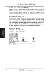
... to ensure that there is powered by the onboard button cell battery. WARNING: You must unplug the power cord to your motherboard. INSTALLATION (Jumpers) 16 ASUS TX97 User's Manual III. The CMOS RAM containing BIOS setup information may be cleared by removing this jumper and attaching a current meter to "Load Setup Defaults" and...
... to ensure that there is powered by the onboard button cell battery. WARNING: You must unplug the power cord to your motherboard. INSTALLATION (Jumpers) 16 ASUS TX97 User's Manual III. The CMOS RAM containing BIOS setup information may be cleared by removing this jumper and attaching a current meter to "Load Setup Defaults" and...

User Manual
Page 17
Voltage Regulator Output Selection (VID0, 1, 2, 3) These jumpers set the voltage supplied to be [1-2] or [2-3] or [----] ASUS TX97 User's Manual 17 Because CPU designs change rapidly, the following chart is only intended as a simple quideline and is not intended to the CPU. Manufacturer CPU Type ...
Voltage Regulator Output Selection (VID0, 1, 2, 3) These jumpers set the voltage supplied to be [1-2] or [2-3] or [----] ASUS TX97 User's Manual 17 Because CPU designs change rapidly, the following chart is only intended as a simple quideline and is not intended to the CPU. Manufacturer CPU Type ...

User Manual
Page 18
... clock generator what frequency to send to BUS Frequency Ratio (BF0, BF1) These jumpers set together with the Cyrix PR166+ installed on this motherboard. 18 ASUS TX97 User's Manual
... clock generator what frequency to send to BUS Frequency Ratio (BF0, BF1) These jumpers set together with the Cyrix PR166+ installed on this motherboard. 18 ASUS TX97 User's Manual

User Manual
Page 19
... SDRAM cells, Socket 3 must be empty Total Memory x1 Socket 2 SDRAM 8MB, 16MB, 32MB x1 SDRAM 64MB, 128MB - Slot 3 must be empty. INSTALLATION (System Memory) ASUS TX97 User's Manual 19 Maximum memory of either 8, 16, or 32, 64, or 128MB. III. INSTALLATION 2.
... SDRAM cells, Socket 3 must be empty Total Memory x1 Socket 2 SDRAM 8MB, 16MB, 32MB x1 SDRAM 64MB, 128MB - Slot 3 must be empty. INSTALLATION (System Memory) ASUS TX97 User's Manual 19 Maximum memory of either 8, 16, or 32, 64, or 128MB. III. INSTALLATION 2.

User Manual
Page 20
... will only fit in the orientation as shown. INSTALLATION (System Memory) DRAM Key Position RFU Unbuffered Buffered Voltage 5.0V The notch on this motherboard. 20 ASUS TX97 User's Manual INSTALLATION DIMM Memory Installation Procedures: Insert the module as shown.
... will only fit in the orientation as shown. INSTALLATION (System Memory) DRAM Key Position RFU Unbuffered Buffered Voltage 5.0V The notch on this motherboard. 20 ASUS TX97 User's Manual INSTALLATION DIMM Memory Installation Procedures: Insert the module as shown.


