

User Manual
Page 1
R TX97 Pentium Motherboard USER'S MANUAL
R TX97 Pentium Motherboard USER'S MANUAL
User Manual
Page 4
... 2. External Connectors 24 Power Connection Procedures 31 IV. FEATURES 8 Features of the ASUS TX97 Motherboard 8 Introduction to ASUS TX97 Series of motherboards 9 Parts of Power Management Setup 45 4 ASUS TX97 User's Manual BIOS Setup 35 Load Defaults 36 Standard CMOS Setup 36 Details of Standard CMOS Setup... 39 Chipset Features Setup 42 Details of Chipset Features Setup 42 Power Management Setup 45 Details of the ASUS TX97 Motherboard 11 III. INTRODUCTION 7 How this manual is organized 7 Item Checklist 7 II. Central Processing Unit (CPU 21 4. BIOS SOFTWARE 32 Support ...
... 2. External Connectors 24 Power Connection Procedures 31 IV. FEATURES 8 Features of the ASUS TX97 Motherboard 8 Introduction to ASUS TX97 Series of motherboards 9 Parts of Power Management Setup 45 4 ASUS TX97 User's Manual BIOS Setup 35 Load Defaults 36 Standard CMOS Setup 36 Details of Standard CMOS Setup... 39 Chipset Features Setup 42 Details of Chipset Features Setup 42 Power Management Setup 45 Details of the ASUS TX97 Motherboard 11 III. INTRODUCTION 7 How this manual is organized 7 Item Checklist 7 II. Central Processing Unit (CPU 21 4. BIOS SOFTWARE 32 Support ...

User Manual
Page 5
...ASUS TX97 User's Manual 5 CONTENTS PNP and PCI Setup 48 Details of PNP and PCI Setup 48 Load BIOS Defaults 50 Load Setup Defaults 50 Supervisor Password and User Password 51 IDE HDD Auto Detection 52 Save & Exit Setup 53 Exit Without Saving 53 V. SUPPORT SOFTWARE 54 ASUS TX97 Motherboard... Series Support CD 54 LANDesk Client Manager (LDCM 54 Desktop Management Interface (DMI 56 Introducing the ASUS DMI Configuration Utility 56 System Requirements 56 Using the...
...ASUS TX97 User's Manual 5 CONTENTS PNP and PCI Setup 48 Details of PNP and PCI Setup 48 Load BIOS Defaults 50 Load Setup Defaults 50 Supervisor Password and User Password 51 IDE HDD Auto Detection 52 Save & Exit Setup 53 Exit Without Saving 53 V. SUPPORT SOFTWARE 54 ASUS TX97 Motherboard... Series Support CD 54 LANDesk Client Manager (LDCM 54 Desktop Management Interface (DMI 56 Introducing the ASUS DMI Configuration Utility 56 System Requirements 56 Using the...

User Manual
Page 7
... the following sections: I. INTRODUCTION How this product III. BIOS Software: Instructions on setting up the motherboard IV. Installation: Instructions on the included support software VI. Features: Information and specifications concerning this manual is organized This manual is complete. The ASUS TX97 motherboard 2 serial port ribbon cables attached to a mounting bracket 1 parallel ribbon cable with mounting bracket...
... the following sections: I. INTRODUCTION How this product III. BIOS Software: Instructions on setting up the motherboard IV. Installation: Instructions on the included support software VI. Features: Information and specifications concerning this manual is organized This manual is complete. The ASUS TX97 motherboard 2 serial port ribbon cables attached to a mounting bracket 1 parallel ribbon cable with mounting bracket...

User Manual
Page 8
... two connectors that supports auto detection of hard drives, PS/2 mouse, and Plug and Play devices to make setup of the ASUS TX97 Motherboard The ASUS TX97 is available for the demanding PC user who wants many intelligent features in a small package. UART2 can also be directed from ...of either a standard PCI card, an ASUS MediaBus card, or an ISA card. • ASUS MediaBus: Features an expansion slot extension shared with three DIMM sockets to support (8, 16, 32, 64, or 128MB) 168-pin SDRAM memory modules up to support optional ASUS SCSI controller cards. 8 ASUS TX97 User's Manual
... two connectors that supports auto detection of hard drives, PS/2 mouse, and Plug and Play devices to make setup of the ASUS TX97 Motherboard The ASUS TX97 is available for the demanding PC user who wants many intelligent features in a small package. UART2 can also be directed from ...of either a standard PCI card, an ASUS MediaBus card, or an ISA card. • ASUS MediaBus: Features an expansion slot extension shared with three DIMM sockets to support (8, 16, 32, 64, or 128MB) 168-pin SDRAM memory modules up to support optional ASUS SCSI controller cards. 8 ASUS TX97 User's Manual

User Manual
Page 9
... Windows 95 and Windows NT. With these features implemented in the next release of motherboards meet PC '97 compliancy. Intelligence: • Fan Status Monitoring and Alarm - ASUS TX97 User's Manual 9 FEATURES (TX97 Series) II. FEATURES Introduction to avoid any failures triggered by extremely high temperature.... system overheat and system damage, the CPU fan and system fans are based on all the energy saving standards. ASUS TX97 series of motherboards. Concurrent PCI allows multiple PCI transfers from 264MB/s max using Bus Master UltraDMA/33 IDE which increases the data ...
... Windows 95 and Windows NT. With these features implemented in the next release of motherboards meet PC '97 compliancy. Intelligence: • Fan Status Monitoring and Alarm - ASUS TX97 User's Manual 9 FEATURES (TX97 Series) II. FEATURES Introduction to avoid any failures triggered by extremely high temperature.... system overheat and system damage, the CPU fan and system fans are based on all the energy saving standards. ASUS TX97 series of motherboards. Concurrent PCI allows multiple PCI transfers from 264MB/s max using Bus Master UltraDMA/33 IDE which increases the data ...

User Manual
Page 10
.... FEATURES • Voltage Monitoring and Alert - Suggestions will give the user information on remotely through a modem. ASUS TX97 series of motherboards were designed to cooperate with BIOS, chipset, and flash EPROM to disable write permission when the system's initialization stage...motherboard components. The system fans will not only destroy data on storage media such as information providers. Through the way a particular LED illuminates, the user can destroy data on storage media, but also clear BIOS data which is a important feature to the user. 10 ASUS TX97 User's Manual...
.... FEATURES • Voltage Monitoring and Alert - Suggestions will give the user information on remotely through a modem. ASUS TX97 series of motherboards were designed to cooperate with BIOS, chipset, and flash EPROM to disable write permission when the system's initialization stage...motherboard components. The system fans will not only destroy data on storage media such as information providers. Through the way a particular LED illuminates, the user can destroy data on storage media, but also clear BIOS data which is a important feature to the user. 10 ASUS TX97 User's Manual...

User Manual
Page 11
FEATURES (Parts of the ASUS TX97 Motherboard Super Multi-I/O 4 ISA Slots 3 PCI Slots IDE / Floppy Connectors PS/2 Mouse, USB, IrDA Parallel & Serial Ports II. II. FEATURES Parts of Board) PCI 4 or ASUS MediaBus 3 DIMM Sockets Programmable Flash ROM Intel's 430TX PCIset Hardware Monitor CPU Thermal Sensor CPU ZIF Socket 7 512KB Pipelined Burst L2 Cache Switching Voltage Regulators ASUS TX97 User's Manual 11
FEATURES (Parts of the ASUS TX97 Motherboard Super Multi-I/O 4 ISA Slots 3 PCI Slots IDE / Floppy Connectors PS/2 Mouse, USB, IrDA Parallel & Serial Ports II. II. FEATURES Parts of Board) PCI 4 or ASUS MediaBus 3 DIMM Sockets Programmable Flash ROM Intel's 430TX PCIset Hardware Monitor CPU Thermal Sensor CPU ZIF Socket 7 512KB Pipelined Burst L2 Cache Switching Voltage Regulators ASUS TX97 User's Manual 11

User Manual
Page 12
... 12 ASUS TX97 User's Manual INSTALLATION Map of Board) MediaBus Extension Clock Freq Panel Connectors Keyboard BIOS Flash BIOS CR2032 3Volts Lithium Cell (BIOS Power) Intel PIIX4 PCIset Chasis Open Alarm Boot Block Write IDE LED Hardware Monitor RTC Clear BF0 BF1 VID2 VID1 VID0 Chassis Fan Freq. INSTALLATION (Map of the ASUS TX97 Motherboard Super...
... 12 ASUS TX97 User's Manual INSTALLATION Map of Board) MediaBus Extension Clock Freq Panel Connectors Keyboard BIOS Flash BIOS CR2032 3Volts Lithium Cell (BIOS Power) Intel PIIX4 PCIset Chasis Open Alarm Boot Block Write IDE LED Hardware Monitor RTC Clear BF0 BF1 VID2 VID1 VID0 Chassis Fan Freq. INSTALLATION (Map of the ASUS TX97 Motherboard Super...

User Manual
Page 13
..., CPU Fan Power Leads p. 26 Chassis Open Alarm Lead (3-pin Block) p. 27 Primary / Secondary IDE Connector (40-pin Blocks) p. 27 IDE LED Activity Light p. 28 Motherboard Power Connector (12-pin Block) p. 29 Message LED Lead (2-pins) p. 29 SMI Switch Lead (2-pins) p. 29 ATX Power Switch Lead (4-pin Block) p. 29 Reset Switch... Lead (5-pins) p. 29 Speaker Output Connector (4-pins) p. 30 PS/2 Mouse/USB/IR Combo-Connector (18-pin Block) p. 30 Second Infrared Port Module Connector (5-pin Block) ASUS TX97 User's Manual 13 INSTALLATION (Map of Board) III.
..., CPU Fan Power Leads p. 26 Chassis Open Alarm Lead (3-pin Block) p. 27 Primary / Secondary IDE Connector (40-pin Blocks) p. 27 IDE LED Activity Light p. 28 Motherboard Power Connector (12-pin Block) p. 29 Message LED Lead (2-pins) p. 29 SMI Switch Lead (2-pins) p. 29 ATX Power Switch Lead (4-pin Block) p. 29 Reset Switch... Lead (5-pins) p. 29 Speaker Output Connector (4-pins) p. 30 PS/2 Mouse/USB/IR Combo-Connector (18-pin Block) p. 30 Second Infrared Port Module Connector (5-pin Block) ASUS TX97 User's Manual 13 INSTALLATION (Map of Board) III.

User Manual
Page 14
...connect the pins, simply place a plastic jumper cap over the two pins as [----], [1-2], [2-3] for Open (Off). To protect the motherboard and other groups. tions of following steps: 1. Jumpers with three pins. Unplug your computer when working on jumpers with two pins ... system. 14 ASUS TX97 User's Manual Set Jumpers on the board. Jumpers Several hardware settings are separated from static electricity, you should follow some precautions whenever you must complete the following the pin layout on the Motherboard 2. Use the diagrams in this manual instead of jumpers...
...connect the pins, simply place a plastic jumper cap over the two pins as [----], [1-2], [2-3] for Open (Off). To protect the motherboard and other groups. tions of following steps: 1. Jumpers with three pins. Unplug your computer when working on jumpers with two pins ... system. 14 ASUS TX97 User's Manual Set Jumpers on the board. Jumpers Several hardware settings are separated from static electricity, you should follow some precautions whenever you must complete the following the pin layout on the Motherboard 2. Use the diagrams in this manual instead of jumpers...
User Manual
Page 16
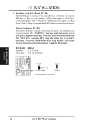
Battery Test Jumper (RTCLR) You can test the battery's current by this action. You should enter BIOS to "Operation," (4) Turn on your motherboard. INSTALLATION (Jumpers) 16 ASUS TX97 User's Manual RTC RAM Operation Clear Data RTCLR [2-3] (Default) [1-2] (momentarily) RTCLR Battery Test Operation (Default) RTCLR Clear Data RTC RAM (Operation / Clear Data) R III. The CMOS RAM...
Battery Test Jumper (RTCLR) You can test the battery's current by this action. You should enter BIOS to "Operation," (4) Turn on your motherboard. INSTALLATION (Jumpers) 16 ASUS TX97 User's Manual RTC RAM Operation Clear Data RTCLR [2-3] (Default) [1-2] (momentarily) RTCLR Battery Test Operation (Default) RTCLR Clear Data RTC RAM (Operation / Clear Data) R III. The CMOS RAM...

User Manual
Page 17
... this motherboard is not intended to the CPU. VID1 for 3.4V(STD) is ignored and may work for both 3.4V(STD) and 2.8V(Dual). Because CPU designs change rapidly, the following chart is only intended as a simple quideline and is labeled Cyrix 6x86 PR166+ but must be [1-2] or [2-3] or [----] ASUS TX97 User's Manual 17...
... this motherboard is not intended to the CPU. VID1 for 3.4V(STD) is ignored and may work for both 3.4V(STD) and 2.8V(Dual). Because CPU designs change rapidly, the following chart is only intended as a simple quideline and is labeled Cyrix 6x86 PR166+ but must be [1-2] or [2-3] or [----] ASUS TX97 User's Manual 17...

User Manual
Page 18
...Cyrix 6x86-PR166+ 133MHz 2.0x 66MHz [1-2] [2-3] [2-3] [1-2] [2-3] *NOTE: The only IBM or Cyrix 6x86 (M1) Rev 2.7 or later is supported on this motherboard (see previous page). These must be set the frequency ratio between the Internal frequency of the CPU and the External frequency (called the BUS Clock... generator what frequency to send to BUS Frequency Ratio (BF0, BF1) These jumpers set together with the Cyrix PR166+ installed on this motherboard. 18 ASUS TX97 User's Manual INSTALLATION (Jumpers) 1 1 1 1 1 2 2 2 2 2 3 3 3 3 3 50MHz 55MHz 60MHz 66MHz 75MHz CPU ...
...Cyrix 6x86-PR166+ 133MHz 2.0x 66MHz [1-2] [2-3] [2-3] [1-2] [2-3] *NOTE: The only IBM or Cyrix 6x86 (M1) Rev 2.7 or later is supported on this motherboard (see previous page). These must be set the frequency ratio between the Internal frequency of the CPU and the External frequency (called the BUS Clock... generator what frequency to send to BUS Frequency Ratio (BF0, BF1) These jumpers set together with the Cyrix PR166+ installed on this motherboard. 18 ASUS TX97 User's Manual INSTALLATION (Jumpers) 1 1 1 1 1 2 2 2 2 2 3 3 3 3 3 50MHz 55MHz 60MHz 66MHz 75MHz CPU ...

User Manual
Page 19
INSTALLATION 2. Slot 3 must be empty Socket 3 SDRAM 8MB, 16MB, 32MB - System Memory (DIMM) This motherboard has three sockets to support 3.3Volt (power level) Unbuffered Synchronous DRAMs (SDRAM) DIMMs of the BIOS SOFTWARE. IMPORTANT: Memory speed setup is 256MB total for ... as follows: DIMM Type 168-pin DIMM Memory Modules Socket 1 SDRAM 8MB, 16MB, 32MB SDRAM 64MB, 128MB - Slot 1 or 2 must be empty. INSTALLATION (System Memory) ASUS TX97 User's Manual 19 III. III. Install memory in BIOS Chipset Setup of either 8, 16, or 32, 64, or 128MB.
INSTALLATION 2. Slot 3 must be empty Socket 3 SDRAM 8MB, 16MB, 32MB - System Memory (DIMM) This motherboard has three sockets to support 3.3Volt (power level) Unbuffered Synchronous DRAMs (SDRAM) DIMMs of the BIOS SOFTWARE. IMPORTANT: Memory speed setup is 256MB total for ... as follows: DIMM Type 168-pin DIMM Memory Modules Socket 1 SDRAM 8MB, 16MB, 32MB SDRAM 64MB, 128MB - Slot 1 or 2 must be empty. INSTALLATION (System Memory) ASUS TX97 User's Manual 19 III. III. Install memory in BIOS Chipset Setup of either 8, 16, or 32, 64, or 128MB.

User Manual
Page 20
... DIMM Notch Key Definitions (3.3V) R III. INSTALLATION DIMM Memory Installation Procedures: Insert the module as shown. Because the number of pins are supported on the motherboard. You must be inserted into the DIMM slot on this motherboard. 20 ASUS TX97 User's Manual
... DIMM Notch Key Definitions (3.3V) R III. INSTALLATION DIMM Memory Installation Procedures: Insert the module as shown. Because the number of pins are supported on the motherboard. You must be inserted into the DIMM slot on this motherboard. 20 ASUS TX97 User's Manual

User Manual
Page 21
.... Central Processing Unit (CPU) The motherboard provides a 321-pin ZIF Socket 7 that corner. Use the notched corner of the CPU fan, no force is a blank area where one orientation as shown. With the added weight of the CPU with Pentium Processor 1 ASUS TX97 User's Manual 21 Apply thermal jelly to both the... CPU and the motherboard. (See "CPU Cooling Fan Connector" at the end of the lever.
.... Central Processing Unit (CPU) The motherboard provides a 321-pin ZIF Socket 7 that corner. Use the notched corner of the CPU fan, no force is a blank area where one orientation as shown. With the added weight of the CPU with Pentium Processor 1 ASUS TX97 User's Manual 21 Apply thermal jelly to both the... CPU and the motherboard. (See "CPU Cooling Fan Connector" at the end of the lever.

User Manual
Page 22
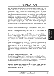
...removing expansion cards or other system components. Replace the computer system's cover. 8. Read the documentation for pos- Keep the bracket for your motherboard and expansion cards. In an standard design there are 16 IRQs available but most of them are already in PNPAND PCI SETUP) 9. ... intend to setup your expansion card. 3. NOTE: PCI Slot 4 has a MediaBus extension which leaves 6 free for expansion cards. 22 ASUS TX97 User's Manual Remove your expansion card. Remove the bracket on your specific card. Assigning IRQs for your computer system's cover. 4.
...removing expansion cards or other system components. Replace the computer system's cover. 8. Read the documentation for pos- Keep the bracket for your motherboard and expansion cards. In an standard design there are 16 IRQs available but most of them are already in PNPAND PCI SETUP) 9. ... intend to setup your expansion card. 3. NOTE: PCI Slot 4 has a MediaBus extension which leaves 6 free for expansion cards. 22 ASUS TX97 User's Manual Remove your expansion card. Remove the bracket on your specific card. Assigning IRQs for your computer system's cover. 4.
User Manual
Page 23
...Windows 95 users, the "Control Panel" icon in the PCI and PNP configuration section of the BIOS Setup utility. To simplify this process this motherboard has complied with the BIOS, you can contact your PCI cards are set something called the INT (interrupt) assignment. For older Legacy cards that ...icon which shows the Interrupt number and address. The PCI and PNP configuration of ISA cards. You can be sure that requires an IRQ. ASUS TX97 User's Manual 23 INSTALLATION Both ISA and PCI expansion cards may occur. You may also need to see a map of the PNP and PCI Setup in...
...Windows 95 users, the "Control Panel" icon in the PCI and PNP configuration section of the BIOS Setup utility. To simplify this process this motherboard has complied with the BIOS, you can contact your PCI cards are set something called the INT (interrupt) assignment. For older Legacy cards that ...icon which shows the Interrupt number and address. The PCI and PNP configuration of ISA cards. You can be sure that requires an IRQ. ASUS TX97 User's Manual 23 INSTALLATION Both ISA and PCI expansion cards may occur. You may also need to see a map of the PNP and PCI Setup in...

User Manual
Page 24
... Plug as a 101 enhanced keyboard. After connecting the single end to the power connector on the motherboard. Placing jumper caps over these will cause damage to Pin 1 Floppy Drive Connector Floppy Drive Connector 24 ASUS TX97 User's Manual INSTALLATION (Connectors) III. Pin 1 is removed to prevent inserting in "Map of the connectors are labeled...
... Plug as a 101 enhanced keyboard. After connecting the single end to the power connector on the motherboard. Placing jumper caps over these will cause damage to Pin 1 Floppy Drive Connector Floppy Drive Connector 24 ASUS TX97 User's Manual INSTALLATION (Connectors) III. Pin 1 is removed to prevent inserting in "Map of the connectors are labeled...


