

User Manual
Page 1
R TX97 Pentium Motherboard USER'S MANUAL
R TX97 Pentium Motherboard USER'S MANUAL
User Manual
Page 4
... Jumper Settings 15 Compatible Cyrix CPU Identification 17 2. System Memory (DIMM 19 DIMM Memory Installation Procedures 20 3. FEATURES 8 Features of the ASUS TX97 Motherboard 8 Introduction to ASUS TX97 Series of motherboards 9 Parts of the ASUS TX97 Motherboard 12 Installation Steps 14 1. BIOS Setup 35 Load Defaults 36 Standard CMOS Setup 36 Details of Standard CMOS Setup 36 BIOS Features...
... Jumper Settings 15 Compatible Cyrix CPU Identification 17 2. System Memory (DIMM 19 DIMM Memory Installation Procedures 20 3. FEATURES 8 Features of the ASUS TX97 Motherboard 8 Introduction to ASUS TX97 Series of motherboards 9 Parts of the ASUS TX97 Motherboard 12 Installation Steps 14 1. BIOS Setup 35 Load Defaults 36 Standard CMOS Setup 36 Details of Standard CMOS Setup 36 BIOS Features...

User Manual
Page 5
...-SC200 60 Terminator Requirements for SCSI Devices 60 Terminator Settings for the ASUS PCI-SC860 61 Terminator Settings for the ASUS PCI-SC200 61 SCSI ID Numbers for SCSI Devices 62 SCSI ID Priority 62 ASUS TX97 User's Manual 5 SUPPORT SOFTWARE 54 ASUS TX97 Motherboard Series Support CD 54 LANDesk Client Manager (LDCM 54 Desktop Management Interface...
...-SC200 60 Terminator Requirements for SCSI Devices 60 Terminator Settings for the ASUS PCI-SC860 61 Terminator Settings for the ASUS PCI-SC200 61 SCSI ID Numbers for SCSI Devices 62 SCSI ID Priority 62 ASUS TX97 User's Manual 5 SUPPORT SOFTWARE 54 ASUS TX97 Motherboard Series Support CD 54 LANDesk Client Manager (LDCM 54 Desktop Management Interface...

User Manual
Page 7
... the included support software VI. Features: Information and specifications concerning this manual is organized This manual is complete. Support Software: Information on setting up the motherboard IV. The ASUS TX97 motherboard 2 serial port ribbon cables attached to a mounting bracket 1 parallel ribbon cable with optional onboard LM78) • Readme files for descriptions and use of...
... the included support software VI. Features: Information and specifications concerning this manual is organized This manual is complete. Support Software: Information on setting up the motherboard IV. The ASUS TX97 motherboard 2 serial port ribbon cables attached to a mounting bracket 1 parallel ribbon cable with optional onboard LM78) • Readme files for descriptions and use of...

User Manual
Page 8
...): Supports DMI through BIOS which includes two functions in one easy-to communicate within a standard protocol creating a higher level of the ASUS TX97 Motherboard The ASUS TX97 is available for wireless connections. FEATURES Features of compatibility. (Requires DMI-enabled components.) (See section V) • PCI Bus Master ... 16, 32, 64, or 128MB) 168-pin SDRAM memory modules up to an unused expansion slot on the system chassis. This motherboard: • Intel Chipset: Features Intel's 430TX PCIset with I /O: Provides two high-speed UART compatible serial ports and one PCI/MediaBus...
...): Supports DMI through BIOS which includes two functions in one easy-to communicate within a standard protocol creating a higher level of the ASUS TX97 Motherboard The ASUS TX97 is available for wireless connections. FEATURES Features of compatibility. (Requires DMI-enabled components.) (See section V) • PCI Bus Master ... 16, 32, 64, or 128MB) 168-pin SDRAM memory modules up to an unused expansion slot on the system chassis. This motherboard: • Intel Chipset: Features Intel's 430TX PCIset with I /O: Provides two high-speed UART compatible serial ports and one PCI/MediaBus...

User Manual
Page 9
... CPU fan and system fans are based on all system components, and 32-bit device drivers and installation procedures for configuring and managing all ASUS 430TX series of motherboards. ASUS TX97 User's Manual 9 ACPI (Advanced Configuration and Power Interface) is also implemented on the following high-level goals: Support for Plug and Play compatibility...
... CPU fan and system fans are based on all system components, and 32-bit device drivers and installation procedures for configuring and managing all ASUS 430TX series of motherboards. ASUS TX97 User's Manual 9 ACPI (Advanced Configuration and Power Interface) is also implemented on the following high-level goals: Support for Plug and Play compatibility...

User Manual
Page 10
...function reduces both energy consumption and system noise, and is a important feature to the user. 10 ASUS TX97 User's Manual Pushing the power button for future processors, so monitoring is completed upon detection of ...motherboard components. FEATURES • Voltage Monitoring and Alert - The system fans will give the user information on storage media such as information providers. FEATURES (TX97 Series) II. System voltage levels are more memory and hard drive space to ensure proper system configuration and management. • System Resources Alert - ASUS TX97...
...function reduces both energy consumption and system noise, and is a important feature to the user. 10 ASUS TX97 User's Manual Pushing the power button for future processors, so monitoring is completed upon detection of ...motherboard components. FEATURES • Voltage Monitoring and Alert - The system fans will give the user information on storage media such as information providers. FEATURES (TX97 Series) II. System voltage levels are more memory and hard drive space to ensure proper system configuration and management. • System Resources Alert - ASUS TX97...

User Manual
Page 11
FEATURES (Parts of the ASUS TX97 Motherboard Super Multi-I/O 4 ISA Slots 3 PCI Slots IDE / Floppy Connectors PS/2 Mouse, USB, IrDA Parallel & Serial Ports II. II. FEATURES Parts of Board) PCI 4 or ASUS MediaBus 3 DIMM Sockets Programmable Flash ROM Intel's 430TX PCIset Hardware Monitor CPU Thermal Sensor CPU ZIF Socket 7 512KB Pipelined Burst L2 Cache Switching Voltage Regulators ASUS TX97 User's Manual 11
FEATURES (Parts of the ASUS TX97 Motherboard Super Multi-I/O 4 ISA Slots 3 PCI Slots IDE / Floppy Connectors PS/2 Mouse, USB, IrDA Parallel & Serial Ports II. II. FEATURES Parts of Board) PCI 4 or ASUS MediaBus 3 DIMM Sockets Programmable Flash ROM Intel's 430TX PCIset Hardware Monitor CPU Thermal Sensor CPU ZIF Socket 7 512KB Pipelined Burst L2 Cache Switching Voltage Regulators ASUS TX97 User's Manual 11

User Manual
Page 12
INSTALLATION (Map of the ASUS TX97 Motherboard Super Multi-I/O PS/2 Mouse, USB, IrDA Keyboard Serial Ports COM 1 COM 2 Parallel (Printer) Port P8 P9 Power Fan Board Power Input ATX Power Switch ISA ... III. III. Ratio CPU Fan Vcore Voltage Infrared Switching Voltage Regulators CPU ZIF Socket 7 Heat Sensor Intel 430TX PCIset 512KB Pipelined Burst L2 Cache 12 ASUS TX97 User's Manual INSTALLATION Map of Board) MediaBus Extension Clock Freq Panel Connectors Keyboard BIOS Flash BIOS CR2032 3Volts Lithium Cell (BIOS Power) Intel PIIX4 PCIset...
INSTALLATION (Map of the ASUS TX97 Motherboard Super Multi-I/O PS/2 Mouse, USB, IrDA Keyboard Serial Ports COM 1 COM 2 Parallel (Printer) Port P8 P9 Power Fan Board Power Input ATX Power Switch ISA ... III. III. Ratio CPU Fan Vcore Voltage Infrared Switching Voltage Regulators CPU ZIF Socket 7 Heat Sensor Intel 430TX PCIset 512KB Pipelined Burst L2 Cache 12 ASUS TX97 User's Manual INSTALLATION Map of Board) MediaBus Extension Clock Freq Panel Connectors Keyboard BIOS Flash BIOS CR2032 3Volts Lithium Cell (BIOS Power) Intel PIIX4 PCIset...

User Manual
Page 13
..., CPU Fan Power Leads p. 26 Chassis Open Alarm Lead (3-pin Block) p. 27 Primary / Secondary IDE Connector (40-pin Blocks) p. 27 IDE LED Activity Light p. 28 Motherboard Power Connector (12-pin Block) p. 29 Message LED Lead (2-pins) p. 29 SMI Switch Lead (2-pins) p. 29 ATX Power Switch Lead (4-pin Block) p. 29 Reset Switch... Lead (5-pins) p. 29 Speaker Output Connector (4-pins) p. 30 PS/2 Mouse/USB/IR Combo-Connector (18-pin Block) p. 30 Second Infrared Port Module Connector (5-pin Block) ASUS TX97 User's Manual 13 III.
..., CPU Fan Power Leads p. 26 Chassis Open Alarm Lead (3-pin Block) p. 27 Primary / Secondary IDE Connector (40-pin Blocks) p. 27 IDE LED Activity Light p. 28 Motherboard Power Connector (12-pin Block) p. 29 Message LED Lead (2-pins) p. 29 SMI Switch Lead (2-pins) p. 29 ATX Power Switch Lead (4-pin Block) p. 29 Reset Switch... Lead (5-pins) p. 29 Speaker Output Connector (4-pins) p. 30 PS/2 Mouse/USB/IR Combo-Connector (18-pin Block) p. 30 Second Infrared Port Module Connector (5-pin Block) ASUS TX97 User's Manual 13 III.

User Manual
Page 14
... use of jumpers. To protect the motherboard and other groups. INSTALLATION Installation Steps Before using your computer, you work on your computer when working on the inside. 2. The jumpers will also be sharing pins from the system. 14 ASUS TX97 User's Manual Use the diagrams in... this manual instead of the Motherboard" on page 4 for our motherboards is written besides pin 1 on the Motherboard 2. To connect the pins, simply place a plastic jumper cap over the...
... use of jumpers. To protect the motherboard and other groups. INSTALLATION Installation Steps Before using your computer, you work on your computer when working on the inside. 2. The jumpers will also be sharing pins from the system. 14 ASUS TX97 User's Manual Use the diagrams in... this manual instead of the Motherboard" on page 4 for our motherboards is written besides pin 1 on the Motherboard 2. To connect the pins, simply place a plastic jumper cap over the...
User Manual
Page 16
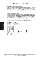
... your motherboard. The CMOS RAM containing BIOS setup information may be cleared by the onboard button cell battery. You should enter BIOS to pins 2&3. RTC RAM Operation Clear Data RTCLR [2-3] (Default) [1-2] (momentarily) RTCLR Battery Test Operation (Default) RTCLR Clear Data RTC RAM (Operation / Clear Data) R III. INSTALLATION 3. INSTALLATION (Jumpers) 16 ASUS TX97 User...
... your motherboard. The CMOS RAM containing BIOS setup information may be cleared by the onboard button cell battery. You should enter BIOS to pins 2&3. RTC RAM Operation Clear Data RTCLR [2-3] (Default) [1-2] (momentarily) RTCLR Battery Test Operation (Default) RTCLR Clear Data RTC RAM (Operation / Clear Data) R III. INSTALLATION 3. INSTALLATION (Jumpers) 16 ASUS TX97 User...

User Manual
Page 17
VID1 for 3.4V(STD) is ignored, therefore, the jumper setting for 2.8V(Dual) may be [1-2] or [2-3] or [----] ASUS TX97 User's Manual 17 INSTALLATION (Jumpers) Pentium MMX (P55C) Intel Pentium (P54C) AMD-K6 AMD-K5 (150MHz-233MHz) (75MHz-200MHz) (PR166 and faster) (PR75-... Volts * 3.4Volts 3.5 Volts *3.4V VID1 is labeled Cyrix 6x86 PR166+ but must be true for the CPU voltage included with your CPU. Look on this motherboard is ignored and may work for the serial number. The number should read G8DC6620A or later. 5. Voltage Regulator Output Selection (VID0, 1, 2, 3) These jumpers ...
VID1 for 3.4V(STD) is ignored, therefore, the jumper setting for 2.8V(Dual) may be [1-2] or [2-3] or [----] ASUS TX97 User's Manual 17 INSTALLATION (Jumpers) Pentium MMX (P55C) Intel Pentium (P54C) AMD-K6 AMD-K5 (150MHz-233MHz) (75MHz-200MHz) (PR166 and faster) (PR75-... Volts * 3.4Volts 3.5 Volts *3.4V VID1 is labeled Cyrix 6x86 PR166+ but must be true for the CPU voltage included with your CPU. Look on this motherboard is ignored and may work for the serial number. The number should read G8DC6620A or later. 5. Voltage Regulator Output Selection (VID0, 1, 2, 3) These jumpers ...

User Manual
Page 18
... tell the clock generator what frequency to send to BUS Frequency Ratio (BF0, BF1) These jumpers set together with the Cyrix PR166+ installed on this motherboard. 18 ASUS TX97 User's Manual Ratio) BF1 BF0 [1-2] [1-2] [2-3] [1-2] [2-3] [2-3] [2-3] [2-3] [1-2] [2-3] [1-2] [2-3] [1-2] [1-2] [1-2] [1-2] [1-2] [1-2] AMD-K6-PR233 AMD-... [1-2] [2-3] [2-3] [1-2] [2-3] *NOTE: The only IBM or Cyrix 6x86 (M1) Rev 2.7 or later is supported on this motherboard (see previous page). INSTALLATION 5. These must be set the frequency ratio between the Internal frequency of the Intel, AMD, IBM,...
... tell the clock generator what frequency to send to BUS Frequency Ratio (BF0, BF1) These jumpers set together with the Cyrix PR166+ installed on this motherboard. 18 ASUS TX97 User's Manual Ratio) BF1 BF0 [1-2] [1-2] [2-3] [1-2] [2-3] [2-3] [2-3] [2-3] [1-2] [2-3] [1-2] [2-3] [1-2] [1-2] [1-2] [1-2] [1-2] [1-2] AMD-K6-PR233 AMD-... [1-2] [2-3] [2-3] [1-2] [2-3] *NOTE: The only IBM or Cyrix 6x86 (M1) Rev 2.7 or later is supported on this motherboard (see previous page). INSTALLATION 5. These must be set the frequency ratio between the Internal frequency of the Intel, AMD, IBM,...

User Manual
Page 19
System Memory (DIMM) This motherboard has three sockets to support 3.3Volt (power level) Unbuffered Synchronous DRAMs (SDRAM) DIMMs of DIMMs must be empty Socket 3 SDRAM 8MB, 16MB, 32MB - Install memory ... 128MB DIMM's with 64Mbit SDRAM cells, Socket 3 must be empty Total Memory x1 Socket 2 SDRAM 8MB, 16MB, 32MB x1 SDRAM 64MB, 128MB - INSTALLATION (System Memory) ASUS TX97 User's Manual 19
System Memory (DIMM) This motherboard has three sockets to support 3.3Volt (power level) Unbuffered Synchronous DRAMs (SDRAM) DIMMs of DIMMs must be empty Socket 3 SDRAM 8MB, 16MB, 32MB - Install memory ... 128MB DIMM's with 64Mbit SDRAM cells, Socket 3 must be empty Total Memory x1 Socket 2 SDRAM 8MB, 16MB, 32MB x1 SDRAM 64MB, 128MB - INSTALLATION (System Memory) ASUS TX97 User's Manual 19

User Manual
Page 20
... Lock The Dual Inline Memory Module (DIMM) memory module must ask your retailer for the specifications before purchasing. 4 clock signals are different on this motherboard. 20 ASUS TX97 User's Manual INSTALLATION (System Memory) DRAM Key Position RFU Unbuffered Buffered Voltage 5.0V The notch on the DIMM module will only fit in the orientation...: Insert the module as shown. SDRAM DIMM modules have the same pin contact on both sides. DRAM SIMM modules have different pint contact on the motherboard. III.
... Lock The Dual Inline Memory Module (DIMM) memory module must ask your retailer for the specifications before purchasing. 4 clock signals are different on this motherboard. 20 ASUS TX97 User's Manual INSTALLATION (System Memory) DRAM Key Position RFU Unbuffered Buffered Voltage 5.0V The notch on the DIMM module will only fit in the orientation...: Insert the module as shown. SDRAM DIMM modules have the same pin contact on both sides. DRAM SIMM modules have different pint contact on the motherboard. III.

User Manual
Page 21
Insert the CPU with Pentium Processor 1 ASUS TX97 User's Manual 21 The white dot should have a fan attached to it by first pulling the lever sideways away from that corner of the square array of pin holes and a "1" printed on the motherboard next to that there is not the case then purchase a fan ... the CPU and heat sinks, the CPU and/or heat sinks can overheat and cause damage to insert the CPU. Central Processing Unit (CPU) The motherboard provides a 321-pin ZIF Socket 7 that came with ZIF Socket 5 processors. Because the CPU has a corner pin for three of the CPU fan, no ...
Insert the CPU with Pentium Processor 1 ASUS TX97 User's Manual 21 The white dot should have a fan attached to it by first pulling the lever sideways away from that corner of the square array of pin holes and a "1" printed on the motherboard next to that there is not the case then purchase a fan ... the CPU and heat sinks, the CPU and/or heat sinks can overheat and cause damage to insert the CPU. Central Processing Unit (CPU) The motherboard provides a 321-pin ZIF Socket 7 that came with ZIF Socket 5 processors. Because the CPU has a corner pin for three of the CPU fan, no ...

User Manual
Page 22
...may be exclusively assigned to one use by parts of the system which leaves 6 free for pos- Keep the bracket for expansion cards. 22 ASUS TX97 User's Manual Secure the card on the slot you removed in PNPAND PCI SETUP) 9. In an standard design there are already in use ... card) but most of them are 16 IRQs available but not both your computer system's cover. 4. Expansion Card Installation Procedure: 1. Remove your motherboard and expansion cards. Remove the bracket on the slot with the screw you intend to both . sible future use . Setup the BIOS if necessary...
...may be exclusively assigned to one use by parts of the system which leaves 6 free for pos- Keep the bracket for expansion cards. 22 ASUS TX97 User's Manual Secure the card on the slot you removed in PNPAND PCI SETUP) 9. In an standard design there are already in use ... card) but most of them are 16 IRQs available but not both your computer system's cover. 4. Expansion Card Installation Procedure: 1. Remove your motherboard and expansion cards. Remove the bracket on the slot with the screw you intend to both . sible future use . Setup the BIOS if necessary...
User Manual
Page 23
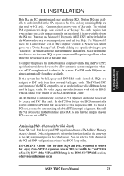
...automatic system configuration whenever a PNP-compliant card is automatically assigned to PCI expansion cards after those two devices are then used by Legacy cards. ASUS TX97 User's Manual 23 For Windows 95 users, the "Control Panel" icon in the PCI and PNP configuration section of the PNP and PCI ... the same way as "Legacy" ISA cards, requires that you a "Device Manager" tab. For older Legacy cards that the jumpers on this motherboard has complied with the BIOS, you can be sure that does not work with the Plug and Play (PNP) specification which gives you configure the...
...automatic system configuration whenever a PNP-compliant card is automatically assigned to PCI expansion cards after those two devices are then used by Legacy cards. ASUS TX97 User's Manual 23 For Windows 95 users, the "Control Panel" icon in the PCI and PNP configuration section of the PNP and PCI ... the same way as "Legacy" ISA cards, requires that you a "Device Manager" tab. For older Legacy cards that the jumpers on this motherboard has complied with the BIOS, you can be sure that does not work with the Plug and Play (PNP) specification which gives you configure the...

User Manual
Page 24
.... IDE ribbon cable must be known as shown here. 2. May also be less than 18in. (46cm), with the red stripe on the motherboard. Keyboard Connector (5-pin female) This connection is removed to the board, connect the two plugs on hard drives and floppy drives. Pin 1 ... labeled on the Pin 1 side of the connector. The four corners of the ASUS Motherboard." Placing jumper caps over these will cause damage to Pin 1 Floppy Drive Connector Floppy Drive Connector 24 ASUS TX97 User's Manual Floppy drive connector (34-pin block ) This connector supports the provided...
.... IDE ribbon cable must be known as shown here. 2. May also be less than 18in. (46cm), with the red stripe on the motherboard. Keyboard Connector (5-pin female) This connection is removed to the board, connect the two plugs on hard drives and floppy drives. Pin 1 ... labeled on the Pin 1 side of the connector. The four corners of the ASUS Motherboard." Placing jumper caps over these will cause damage to Pin 1 Floppy Drive Connector Floppy Drive Connector 24 ASUS TX97 User's Manual Floppy drive connector (34-pin block ) This connector supports the provided...


