

User Guide
Page 1
Motherboard X99-E WS/ USB 3.1
Motherboard X99-E WS/ USB 3.1

User Guide
Page 6
6.2 NVIDIA® SLI™ technology 6-7 6.2.1 Requirements 6-7 6.2.2 Installing two SLI-ready graphics cards 6-7 6.2.3 Installing three SLI-ready graphics cards 6-8 6.2.4 Installing four SLI-ready graphics cards 6-9 6.2.5 Installing the device drivers 6-10 6.2.6 Enabling the NVIDIA® SLI™ technology 6-10 Appendices X99-E WS/USB 3.1 block diagram A-1 Notices ...A-2 ASUS contact information A-6 vi
6.2 NVIDIA® SLI™ technology 6-7 6.2.1 Requirements 6-7 6.2.2 Installing two SLI-ready graphics cards 6-7 6.2.3 Installing three SLI-ready graphics cards 6-8 6.2.4 Installing four SLI-ready graphics cards 6-9 6.2.5 Installing the device drivers 6-10 6.2.6 Enabling the NVIDIA® SLI™ technology 6-10 Appendices X99-E WS/USB 3.1 block diagram A-1 Notices ...A-2 ASUS contact information A-6 vi

User Guide
Page 15
xv Actual product specifications may vary with different models. Package contents Check your motherboard package for the following items ASUS X99-E WS/USB 3.1 motherboard 12 x Serial ATA 6 Gb/s cables 1 x ASUS Q-Shield 1 x 3-WAY SLI bridge connector 1 x 2-in-1 ASUS Q-Connector kit COM port bracket 1 x 4-WAY SLI bridge connector 1 x ASUS SLI™ bridge connector User Manual Support DVD User Guide • If any of the above items is damaged or missing, contact your retailer. • The illustrated items above are for reference only.
xv Actual product specifications may vary with different models. Package contents Check your motherboard package for the following items ASUS X99-E WS/USB 3.1 motherboard 12 x Serial ATA 6 Gb/s cables 1 x ASUS Q-Shield 1 x 3-WAY SLI bridge connector 1 x 2-in-1 ASUS Q-Connector kit COM port bracket 1 x 4-WAY SLI bridge connector 1 x ASUS SLI™ bridge connector User Manual Support DVD User Guide • If any of the above items is damaged or missing, contact your retailer. • The illustrated items above are for reference only.
User Guide
Page 17
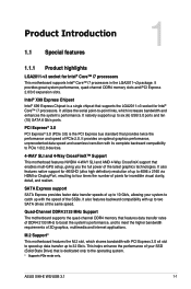
...DDR4 memory slots and PCI Express 2.0/3.0 expansion slots. Intel® X99 Express Chipset Intel® X99 Express Chipset is a single chipset that features data transfer rates of the SSDs. Chapter 1 ASUS X99-E WS/USB 3.1 1-1 SATA Express support SATA Express provides faster data transfer speeds ... 3D graphics, multimedia and Internet applications. PCI Express® 3.0 PCI Express® 3.0 (PCIe 3.0) is dedicated only to six (6) USB 3.0 ports and ten (10) SATA 6 Gb/s ports. It provides an optimal graphics performance, unprecedented data speed and seamless transition with ...
...DDR4 memory slots and PCI Express 2.0/3.0 expansion slots. Intel® X99 Express Chipset Intel® X99 Express Chipset is a single chipset that features data transfer rates of the SSDs. Chapter 1 ASUS X99-E WS/USB 3.1 1-1 SATA Express support SATA Express provides faster data transfer speeds ... 3D graphics, multimedia and Internet applications. PCI Express® 3.0 PCI Express® 3.0 (PCIe 3.0) is dedicated only to six (6) USB 3.0 ports and ten (10) SATA 6 Gb/s ports. It provides an optimal graphics performance, unprecedented data speed and seamless transition with ...
User Guide
Page 19
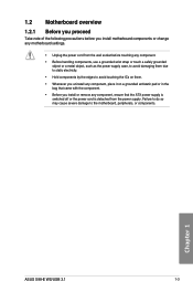
... install or remove any component, ensure that the ATX power supply is switched off or the power cord is detached from the power supply. Chapter 1 ASUS X99-E WS/USB 3.1 1-3 1.2 Motherboard overview 1.2.1 Before you proceed Take note of the following precautions before touching any component. • Before handling components, use a grounded wrist strap or touch...
... install or remove any component, ensure that the ATX power supply is switched off or the power cord is detached from the power supply. Chapter 1 ASUS X99-E WS/USB 3.1 1-3 1.2 Motherboard overview 1.2.1 Before you proceed Take note of the following precautions before touching any component. • Before handling components, use a grounded wrist strap or touch...
User Guide
Page 21
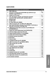
...22. Digital audio connector (4-1 pin SPDIF_OUT) 29. ATX power connectors (24-pin EATXPWR; 8-pin EATX12V; 8-pin EATX12V1; 6-pin EATX12V_1) 3. button 6. USB 2.0 connectors (10-1 pin USB910; USB78) 20. TPM connector (20-1 pin TPM) 21. Front panel audio connector (10-1 pin AAFP) 28. Intel... 1-18 1-18 1-36 1-33 1-34 1-12 1-12 1-35 1-30 1-34 1-15 1-37 1-16 1-14 1-22 1-26 1-28 1-28 1-35 Chapter 1 ASUS X99-E WS/USB 3.1 1-5 CPU, CPU optional, extension, and chassis fan connectors (4-pin CPU_FAN, 4-pin CPU_OPT, 4-pin CHA_FAN1-4 ) 5. Chassis Fan control setting jumper (3-pin CHAFAN_SEL)...
...22. Digital audio connector (4-1 pin SPDIF_OUT) 29. ATX power connectors (24-pin EATXPWR; 8-pin EATX12V; 8-pin EATX12V1; 6-pin EATX12V_1) 3. button 6. USB 2.0 connectors (10-1 pin USB910; USB78) 20. TPM connector (20-1 pin TPM) 21. Front panel audio connector (10-1 pin AAFP) 28. Intel... 1-18 1-18 1-36 1-33 1-34 1-12 1-12 1-35 1-30 1-34 1-15 1-37 1-16 1-14 1-22 1-26 1-28 1-28 1-35 Chapter 1 ASUS X99-E WS/USB 3.1 1-5 CPU, CPU optional, extension, and chassis fan connectors (4-pin CPU_FAN, 4-pin CPU_OPT, 4-pin CHA_FAN1-4 ) 5. Chassis Fan control setting jumper (3-pin CHAFAN_SEL)...

User Guide
Page 23
1.2.4 System memory The motherboard comes with eight DDR 4 (Double Data Rate 4) Quad Inline Memory Modules (DIMM) slots. DO NOT install a DDR, DDR2, or DDR3 memory module to the DDR4 slot. Recommended memory configurations Chapter 1 ASUS X99-E WS/USB 3.1 1-7 A DDR4 module is notched differently from a DDR, DDR2, or DDR3 module.
1.2.4 System memory The motherboard comes with eight DDR 4 (Double Data Rate 4) Quad Inline Memory Modules (DIMM) slots. DO NOT install a DDR, DDR2, or DDR3 memory module to the DDR4 slot. Recommended memory configurations Chapter 1 ASUS X99-E WS/USB 3.1 1-7 A DDR4 module is notched differently from a DDR, DDR2, or DDR3 module.
User Guide
Page 25
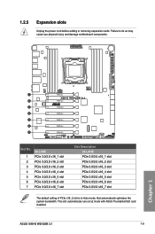
Failure to do so may cause you physical injury and damage motherboard components. This slot automatically runs at x2 mode with ASUS Thunderbolt EX card installed. 1.2.5 Expansion slots Unplug the power cord before adding or removing expansion cards. Chapter 1 Slot No. 1 2 3 4 5 6 7 40-LANE PCIe 3.0/2.0 x16_1 slot PCIe 3.0/2.0 ... 3.0/2.0 x16_5 slot PCIe 3.0/2.0 x16_6 slot PCIe 3.0/2.0 x16_7 slot The default setting of PCIe x16_2 slot is in Auto mode, that automatically optimizes the system bandwidth. ASUS X99-E WS/USB 3.1 1-9
Failure to do so may cause you physical injury and damage motherboard components. This slot automatically runs at x2 mode with ASUS Thunderbolt EX card installed. 1.2.5 Expansion slots Unplug the power cord before adding or removing expansion cards. Chapter 1 Slot No. 1 2 3 4 5 6 7 40-LANE PCIe 3.0/2.0 x16_1 slot PCIe 3.0/2.0 ... 3.0/2.0 x16_5 slot PCIe 3.0/2.0 x16_6 slot PCIe 3.0/2.0 x16_7 slot The default setting of PCIe x16_2 slot is in Auto mode, that automatically optimizes the system bandwidth. ASUS X99-E WS/USB 3.1 1-9

User Guide
Page 27
... - - - - - - - Intel® LAN2 (i210) ASMedia SATA Controller (106SE) ASMedia SATA Controller (1061) Intel® xHCI Intel® EHCI 1 Intel® EHCI 2 shared - - - HD Audio - - - - - - Chapter 1 ASUS X99-E WS/USB 3.1 1-11 PCIe x16_4 shared - - - - - - - shared - - - - shared - - - - -
... - - - - - - - Intel® LAN2 (i210) ASMedia SATA Controller (106SE) ASMedia SATA Controller (1061) Intel® xHCI Intel® EHCI 1 Intel® EHCI 2 shared - - - HD Audio - - - - - - Chapter 1 ASUS X99-E WS/USB 3.1 1-11 PCIe x16_4 shared - - - - - - - shared - - - - shared - - - - -
User Guide
Page 29
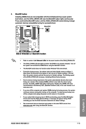
..., and the DIAG_DRAM LED near the MemOK! A message will appear during the tuning process, the system continues memory tuning after using the MemOK! ASUS X99-E WS/USB 3.1 1-13 Chapter 1 button does not function under Windows® OS environment. • During the tuning process, the system loads and tests failsafe... recommend that are not compatible with ones recommended in the Memory QVL (Qualified Vendors Lists) in this user manual or at www.asus.com. • If you download and update to section 1.2.8 Onboard LEDs for successful boot. • Refer to the latest BIOS version ...
..., and the DIAG_DRAM LED near the MemOK! A message will appear during the tuning process, the system continues memory tuning after using the MemOK! ASUS X99-E WS/USB 3.1 1-13 Chapter 1 button does not function under Windows® OS environment. • During the tuning process, the system loads and tests failsafe... recommend that are not compatible with ones recommended in the Memory QVL (Qualified Vendors Lists) in this user manual or at www.asus.com. • If you download and update to section 1.2.8 Onboard LEDs for successful boot. • Refer to the latest BIOS version ...
User Guide
Page 31
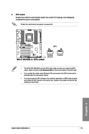
... you have made. Enable this switch under Windows® OS environment, the EPU function will use the last setting you enable the EPU switch. Chapter 1 ASUS X99-E WS/USB 3.1 1-15 However, the system will be activated after the next system bootup. • You may change the EPU settings in the software application or BIOS...
... you have made. Enable this switch under Windows® OS environment, the EPU function will use the last setting you enable the EPU switch. Chapter 1 ASUS X99-E WS/USB 3.1 1-15 However, the system will be activated after the next system bootup. • You may change the EPU settings in the software application or BIOS...

User Guide
Page 33
8. EZ XMP switch Enable this switch to overclock the installed DIMMs, allowing you enable the EZ XMP switch. Chapter 1 ASUS X99-E WS/USB 3.1 1-17 For the location of the EZ XMP LED, refer to enhance the DIMM's speed and performance. The EZ XMP LED (XLED1) lights up when you to section 1.2.8 Onboard LEDs.
8. EZ XMP switch Enable this switch to overclock the installed DIMMs, allowing you enable the EZ XMP switch. Chapter 1 ASUS X99-E WS/USB 3.1 1-17 For the location of the EZ XMP LED, refer to enhance the DIMM's speed and performance. The EZ XMP LED (XLED1) lights up when you to section 1.2.8 Onboard LEDs.

User Guide
Page 35
1.2.8 Onboard LEDs 1. TPU LED (TPU_LED) The TPU LED lights up until the problem is enabled. If an error is found, the critical component's LED stays lit up when the TPU switch is solved. 2. Chapter 1 ASUS X99-E WS/USB 3.1 1-19 Diagnosis LEDs The Diagnosis LEDs provide the status of these key components during POST (PowerOn-Self Test): CPU, memory modules, VGA card, and hard disk drives.
1.2.8 Onboard LEDs 1. TPU LED (TPU_LED) The TPU LED lights up until the problem is enabled. If an error is found, the critical component's LED stays lit up when the TPU switch is solved. 2. Chapter 1 ASUS X99-E WS/USB 3.1 1-19 Diagnosis LEDs The Diagnosis LEDs provide the status of these key components during POST (PowerOn-Self Test): CPU, memory modules, VGA card, and hard disk drives.
User Guide
Page 37
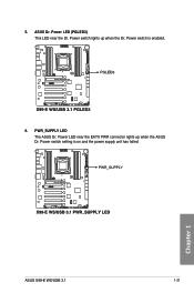
5. PWR_SUPPLY LED The ASUS Dr. Power LED near the Dr. Power switch lights up when the ASUS Dr. Power switch setting is enabled. 6. Chapter 1 ASUS X99-E WS/USB 3.1 1-21 ASUS Dr. Power LED (PGLED3) This LED near the EATX PWR connector lights up when the Dr. Power switch is on and the power supply unit has failed.
5. PWR_SUPPLY LED The ASUS Dr. Power LED near the Dr. Power switch lights up when the ASUS Dr. Power switch setting is enabled. 6. Chapter 1 ASUS X99-E WS/USB 3.1 1-21 ASUS Dr. Power LED (PGLED3) This LED near the EATX PWR connector lights up when the Dr. Power switch is on and the power supply unit has failed.
User Guide
Page 39
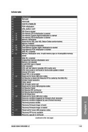
... or Speed CPU mismatch CPU self test failed or possible CPU cache error CPU micro-code is not found (continued on the next page) Chapter 1 ASUS X99-E WS/USB 3.1 1-23 Q-Code table Code 00 02 03 04 06 10 11 - 14 15 - 18 19 - 1C 2B - 2F 30 31 32 - 36 37 - 3A 3B...
... or Speed CPU mismatch CPU self test failed or possible CPU cache error CPU micro-code is not found (continued on the next page) Chapter 1 ASUS X99-E WS/USB 3.1 1-23 Q-Code table Code 00 02 03 04 06 10 11 - 14 15 - 18 19 - 1C 2B - 2F 30 31 32 - 36 37 - 3A 3B...

User Guide
Page 41
... Legacy Boot event Exit Boot Services event Runtime Set Virtual Address MAP Begin Runtime Set Virtual Address MAP End Legacy Option ROM Initialization System Reset USB hot plug PCI bus hot plug Clean-up from the S3 sleep state System is in PIC mode. Interrupt controller is waking up from the... NVRAM settings) Reserved for Legacy Option ROM No Console Output Devices are found No Console Input Devices are not available PCI resource allocation error. Chapter 1 ASUS X99-E WS/USB 3.1 1-25 Code AC AD AE AF B0 B1 B2 B3 B4 B5 B6 B7 B8-
... Legacy Boot event Exit Boot Services event Runtime Set Virtual Address MAP Begin Runtime Set Virtual Address MAP End Legacy Option ROM Initialization System Reset USB hot plug PCI bus hot plug Clean-up from the S3 sleep state System is in PIC mode. Interrupt controller is waking up from the... NVRAM settings) Reserved for Legacy Option ROM No Console Output Devices are found No Console Input Devices are not available PCI resource allocation error. Chapter 1 ASUS X99-E WS/USB 3.1 1-25 Code AC AD AE AF B0 B1 B2 B3 B4 B5 B6 B7 B8-

User Guide
Page 43
..., you intend to create a Serial ATA RAID set using these connectors, set to Serial ATA 6 Gb/s hard disk drives via Serial ATA 6 Gb/s signal cables. ASUS X99-E WS/USB 3.1 1-27 Intel® X99 Serial ATA 6 Gb/s connectors (7-pin SATA6G_12, SATA6G_34, SATA6G_56/SATAEXPRESS_1, SATA6G_78, SATA6G_910) These connectors connect to [AHCI Mode] by default. 3.
..., you intend to create a Serial ATA RAID set using these connectors, set to Serial ATA 6 Gb/s hard disk drives via Serial ATA 6 Gb/s signal cables. ASUS X99-E WS/USB 3.1 1-27 Intel® X99 Serial ATA 6 Gb/s connectors (7-pin SATA6G_12, SATA6G_34, SATA6G_56/SATAEXPRESS_1, SATA6G_78, SATA6G_910) These connectors connect to [AHCI Mode] by default. 3.

User Guide
Page 45
...faster charging time for additional USB 3.0 front or rear panel ports. With an installed USB 3.0 module, you to connect a USB 3.0 module for USB-chargeable devices, optimized power efficiency, and backward compatibility with USB 2.0. 6. USB 3.0 connectors (20-1 ...USB 3.0 ports under Windows® 7. • The plugged USB 3.0 device may run on xHCI or EHCI mode depending on the operating system's setting. • These USB 3.0 ports support native UASP transfer standard in Windows® 8 / Windows® 8.1 and Turbo Mode when using USB 3.0 Boost feature. Chapter 1 ASUS X99-E WS/USB...
...faster charging time for additional USB 3.0 front or rear panel ports. With an installed USB 3.0 module, you to connect a USB 3.0 module for USB-chargeable devices, optimized power efficiency, and backward compatibility with USB 2.0. 6. USB 3.0 connectors (20-1 ...USB 3.0 ports under Windows® 7. • The plugged USB 3.0 device may run on xHCI or EHCI mode depending on the operating system's setting. • These USB 3.0 ports support native UASP transfer standard in Windows® 8 / Windows® 8.1 and Turbo Mode when using USB 3.0 Boost feature. Chapter 1 ASUS X99-E WS/USB...

User Guide
Page 47
...fan connectors! • Ensure that the black wire of each cable matches the ground pin of CPU fan installed and automatically switches the control modes. ASUS X99-E WS/USB 3.1 1-31 Chapter 1 • The CPU_FAN connector supports the CPU fan of maximum 1A (12 W) fan power. • The CPU_FAN and CHA_FAN.... CPU, CPU optional, and chassis fan connectors (4-pin CPU_FAN; 4-pin CPU_OPT; 4-pin CHA_FAN1-4) Connect the fan cables to the fan connectors on X99 platform. • The CPU fan connector detects the type of the connector. • DO NOT forget to connect the fan cables to the CPU...
...fan connectors! • Ensure that the black wire of each cable matches the ground pin of CPU fan installed and automatically switches the control modes. ASUS X99-E WS/USB 3.1 1-31 Chapter 1 • The CPU_FAN connector supports the CPU fan of maximum 1A (12 W) fan power. • The CPU_FAN and CHA_FAN.... CPU, CPU optional, and chassis fan connectors (4-pin CPU_FAN; 4-pin CPU_OPT; 4-pin CHA_FAN1-4) Connect the fan cables to the fan connectors on X99 platform. • The CPU fan connector detects the type of the connector. • DO NOT forget to connect the fan cables to the CPU...

User Guide
Page 49
... power LED. The speaker allows you turn on the system power, and blinks when the system is in sleep or soft-off the system power. ASUS X99-E WS/USB 3.1 1-33 Chapter 1 Pressing the power button turns the system on the operating system settings. Pressing the power switch for more than four seconds while the...
... power LED. The speaker allows you turn on the system power, and blinks when the system is in sleep or soft-off the system power. ASUS X99-E WS/USB 3.1 1-33 Chapter 1 Pressing the power button turns the system on the operating system settings. Pressing the power switch for more than four seconds while the...