User Guide
Page 1
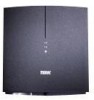
... or consequential damages for one (1) year from the date of nature, commercial use, accident, misuse, abuse or negligence. Replacement as provided under this warranty is only valid in materials or workmanship for breach...Audiovox shall not be replaced without charge. This warranty is the exclusive remedy of AUDIOVOX Corp. 97P007A For customer service and technical information:: 1.800.290.6650 For Customer Service Visit Our Website At www.audiovox.com Product Information, Photos, FAQ's, Owner's Manuals For customer service and technical information:: 1.800.290.6650 TERK and the TERK...
... or consequential damages for one (1) year from the date of nature, commercial use, accident, misuse, abuse or negligence. Replacement as provided under this warranty is only valid in materials or workmanship for breach...Audiovox shall not be replaced without charge. This warranty is the exclusive remedy of AUDIOVOX Corp. 97P007A For customer service and technical information:: 1.800.290.6650 For Customer Service Visit Our Website At www.audiovox.com Product Information, Photos, FAQ's, Owner's Manuals For customer service and technical information:: 1.800.290.6650 TERK and the TERK...
User Guide
Page 2
LF-30S Owner's Manual LF-3OS Wireless A/V Transmitter and Receiver System
LF-30S Owner's Manual LF-3OS Wireless A/V Transmitter and Receiver System
User Guide
Page 3
... extension cords as this product using only the power supply included with all applicable state and federal laws. Refer servicing to another location. LF-30S Important Safety Precautions: 1. Operate this can result in the home or office to qualified personnel only. Disclaimer: This product is designed for transmitting audio and video signals from one location in electrical shock...
... extension cords as this product using only the power supply included with all applicable state and federal laws. Refer servicing to another location. LF-30S Important Safety Precautions: 1. Operate this can result in the home or office to qualified personnel only. Disclaimer: This product is designed for transmitting audio and video signals from one location in electrical shock...
User Guide
Page 4
... -the-art circularly polarized directional transmitting and receiving antennas maximizes signal range and minimizes interference from unwanted signals. The use of state-of TVs, both new and old, and A/V components. By transmitting at a super-high frequency of 2.4 GHz, the FCC-approved LF- 30S avoids the crowded frequency band used by many cordless phones and other wireless A/V transmitters, and utilizes FM rather than lower quality...
... -the-art circularly polarized directional transmitting and receiving antennas maximizes signal range and minimizes interference from unwanted signals. The use of state-of TVs, both new and old, and A/V components. By transmitting at a super-high frequency of 2.4 GHz, the FCC-approved LF- 30S avoids the crowded frequency band used by many cordless phones and other wireless A/V transmitters, and utilizes FM rather than lower quality...
User Guide
Page 5
... the convenience to wirelessly: • Watch cable, satellite programming or DVD movies on any TV in your home, without the hassle and expense of running extra wiring, moving your A/V source or buying another location, and then connect the receiver unit to stereo music on powered speakers inside or outside your door, in the backyard, on any A/V source component you choose between channels for best reception.
... the convenience to wirelessly: • Watch cable, satellite programming or DVD movies on any TV in your home, without the hassle and expense of running extra wiring, moving your A/V source or buying another location, and then connect the receiver unit to stereo music on powered speakers inside or outside your door, in the backyard, on any A/V source component you choose between channels for best reception.
User Guide
Page 6
... (A/V) cables Connects the transmitter and receiver to the receiver 1 - LF- 30S Transmitter (Model LF-30STX) Sends wireless A/V signals to your TV sets and/or A/V components 2 - Power adapters Provides 15V DC power to the transmitter and receiver 1 - Coaxial cable with two type "F" connectors 1 - IR Extender 4 LF-30S Package Contents The following items are all present before discarding the box and beginning the installation. 1 - LF- 30S Receiver (Model LF-30SRX) Receives wireless A/V signals from...
... (A/V) cables Connects the transmitter and receiver to the receiver 1 - LF- 30S Transmitter (Model LF-30STX) Sends wireless A/V signals to your TV sets and/or A/V components 2 - Power adapters Provides 15V DC power to the transmitter and receiver 1 - Coaxial cable with two type "F" connectors 1 - IR Extender 4 LF-30S Package Contents The following items are all present before discarding the box and beginning the installation. 1 - LF- 30S Receiver (Model LF-30SRX) Receives wireless A/V signals from...
User Guide
Page 7
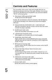
... the back panel. D - 15V DC Power Port (both units - RF Connector (receiver only) Used to connect the RF output from the receiver unit to the RF input of the receiver unit to either channel 3 or 4, to correspond to the TV channel you to remotely control the A/V source that is connected to A/V components and/or TV sets. underneath unit) Set the output of a TV set to the same channel for connection to...
... the back panel. D - 15V DC Power Port (both units - RF Connector (receiver only) Used to connect the RF output from the receiver unit to the RF input of the receiver unit to either channel 3 or 4, to correspond to the TV channel you to remotely control the A/V source that is connected to A/V components and/or TV sets. underneath unit) Set the output of a TV set to the same channel for connection to...

User Guide
Page 8
LF-30S I A Transmitter RIGHT LEFT - + IR EXTENDER VIDEO IN AUDIO IN DC 15v C Receiver RIGHT LEFT - + TO TV VIDEO OUT AUDIO OUT DC 15v H D E F B (under both units) G (under receiver only) 6
LF-30S I A Transmitter RIGHT LEFT - + IR EXTENDER VIDEO IN AUDIO IN DC 15v C Receiver RIGHT LEFT - + TO TV VIDEO OUT AUDIO OUT DC 15v H D E F B (under both units) G (under receiver only) 6
User Guide
Page 9
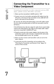
...the A/V device has only one set to the "On" position. 4. Make sure the receiver and transmitter units are set of red, white and yellow A/V cables from the A/V jacks on the back of this manual. Turn the On/Off switch to the same channel. 5. Locate and orient the ...connect the white plugs on both the transmitter and the A/V device. Plug the small end of the power adapter into the back of the transmitter and the other end into a standard A/C wall outlet. Make sure the transmitter's On/Off switch is "Off." 2. LF-30S Connecting the Transmitter to a Video Component Connecting...
...the A/V device has only one set to the "On" position. 4. Make sure the receiver and transmitter units are set of red, white and yellow A/V cables from the A/V jacks on the back of this manual. Turn the On/Off switch to the same channel. 5. Locate and orient the ...connect the white plugs on both the transmitter and the A/V device. Plug the small end of the power adapter into the back of the transmitter and the other end into a standard A/C wall outlet. Make sure the transmitter's On/Off switch is "Off." 2. LF-30S Connecting the Transmitter to a Video Component Connecting...

User Guide
Page 10
OUT VIDEO LINE OUT AUDIO LEFT RIGHT VCR CABLE/ ANT. Cable/Antenna CABLE/ANT. IN CABLE/ANT. IN VIDEO IN AUDIO IN LEFT RIGHT Television Transmitter RIGHT LEFT - + IR EXTENDER VIDEO IN AUDIO IN DC 15v 8 LF-30S VCR users: If you want to view your VCR on a TV located near the transmitter, connect a coaxial cable (not supplied) from the CABLE/ANT OUT (or OUT TO TV) on the VCR to the CABLE/ANT IN port connector on your TV.
OUT VIDEO LINE OUT AUDIO LEFT RIGHT VCR CABLE/ ANT. Cable/Antenna CABLE/ANT. IN CABLE/ANT. IN VIDEO IN AUDIO IN LEFT RIGHT Television Transmitter RIGHT LEFT - + IR EXTENDER VIDEO IN AUDIO IN DC 15v 8 LF-30S VCR users: If you want to view your VCR on a TV located near the transmitter, connect a coaxial cable (not supplied) from the CABLE/ANT OUT (or OUT TO TV) on the VCR to the CABLE/ANT IN port connector on your TV.
User Guide
Page 11
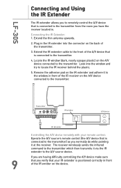
... controlling the A/V device make sure that you verify that your remote control: Operate the A/V source's remote control (the A/V device that is connected to the transmitter) as you normally do while pointing it via the IR extender to locate the IR receiver behind the plastic. 5. LF-30S Connecting and Using the IR Extender The IR extender allows you to remotely control the A/V device that is connected...
... controlling the A/V device make sure that you verify that your remote control: Operate the A/V source's remote control (the A/V device that is connected to the transmitter) as you normally do while pointing it via the IR extender to locate the IR receiver behind the plastic. 5. LF-30S Connecting and Using the IR Extender The IR extender allows you to remotely control the A/V device that is connected...
User Guide
Page 12
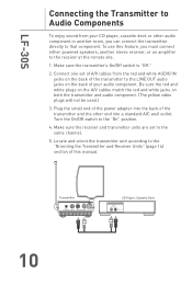
...use this manual. Locate and orient the transmitter unit according to the "Orienting the Transmitter and Receiver Units" (page 14) section of this feature, you can connect the transmitter directly to that component. Make sure the receiver and transmitter units are set of A/V cables from your audio component. Connect one set to the same channel. 5. Plug the small end of the power adapter... you must connect either powered speakers, another stereo receiver, or an amplifier to the receiver at the remote site. 1. Turn the On/Off switch to the "On" position. 4. Make sure the ...
...use this manual. Locate and orient the transmitter unit according to the "Orienting the Transmitter and Receiver Units" (page 14) section of this feature, you can connect the transmitter directly to that component. Make sure the receiver and transmitter units are set of A/V cables from your audio component. Connect one set to the same channel. 5. Plug the small end of the power adapter... you must connect either powered speakers, another stereo receiver, or an amplifier to the receiver at the remote site. 1. Turn the On/Off switch to the "On" position. 4. Make sure the ...
User Guide
Page 13
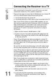
..., use an A/B switch or modulator (not included) and additional coaxial cables to a remote TV (a TV in the small inset picture while enjoying other end into a standard A/C wall outlet. If your TV has only one set to the "Orienting the Transmitter and Receiver Units" (page 14) section of the TV. Connected directly to a TV or another component. Connect one input for instructions on the back of this manual...
..., use an A/B switch or modulator (not included) and additional coaxial cables to a remote TV (a TV in the small inset picture while enjoying other end into a standard A/C wall outlet. If your TV has only one set to the "Orienting the Transmitter and Receiver Units" (page 14) section of the TV. Connected directly to a TV or another component. Connect one input for instructions on the back of this manual...

User Guide
Page 14
LF-30S Television VIDEO IN AUDIO IN CABLE/ ANT. IN LEFT RIGHT Receiver RIGHT LEFT - + TO TV VIDEO OUT AUDIO OUT DC 15v OR 12
LF-30S Television VIDEO IN AUDIO IN CABLE/ ANT. IN LEFT RIGHT Receiver RIGHT LEFT - + TO TV VIDEO OUT AUDIO OUT DC 15v OR 12
User Guide
Page 15
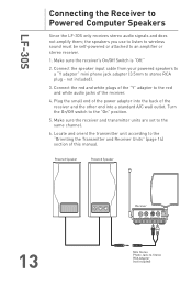
... the receiver. 4. Plug the small end of the power adapter into the back of the receiver and the other end into a standard A/C wall outlet. LF-30S Connecting the Receiver to stereo RCA plug - Connect the speaker input cable from your powered speakers to a "Y adapter" mini phone jack adapter (3.5mm to Powered Computer Speakers Since the LF-30S only receives stereo audio signals and does not amplify them; Make sure the receiver...
... the receiver. 4. Plug the small end of the power adapter into the back of the receiver and the other end into a standard A/C wall outlet. LF-30S Connecting the Receiver to stereo RCA plug - Connect the speaker input cable from your powered speakers to a "Y adapter" mini phone jack adapter (3.5mm to Powered Computer Speakers Since the LF-30S only receives stereo audio signals and does not amplify them; Make sure the receiver...

User Guide
Page 16
... audio using the square directional antennas and your TV, other electronics, large furniture or appliances. For best performance, the units should face each antenna should be positioned vertically. For maximum range between the transmitter and receiver. Note: Although the antennas have been designed to move beyond their range of each other Under no circumstances should be placed as high as your remote control signals using the whip antennas.
... audio using the square directional antennas and your TV, other electronics, large furniture or appliances. For best performance, the units should face each antenna should be positioned vertically. For maximum range between the transmitter and receiver. Note: Although the antennas have been designed to move beyond their range of each other Under no circumstances should be placed as high as your remote control signals using the whip antennas.
User Guide
Page 17
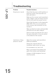
... the receiver and transmitter's antenna orientation. LF-30S Troubleshooting Problem No picture or sound Possible Solutions Check that the power on/off . If a microwave is set to the receiver and transmitter are using. Make sure the receiver and transmitter's power adapter cords are both switched on . Check that the transmitter and receiver are all components (DVD, VCR, TV etc.) in use connected to the same channel. Change the channels...
... the receiver and transmitter's antenna orientation. LF-30S Troubleshooting Problem No picture or sound Possible Solutions Check that the power on/off . If a microwave is set to the receiver and transmitter are using. Make sure the receiver and transmitter's power adapter cords are both switched on . Check that the transmitter and receiver are all components (DVD, VCR, TV etc.) in use connected to the same channel. Change the channels...

User Guide
Page 18
Never use any type of abrasive scouring powder, cleaner or solvent. 16 LF-30S Specifications Approvals: UL/CSA/FCC/ISC Channels: 4 Operating Frequencies: Channel A 2.413Ghz Channel B 2.431Ghz Channel C 2.45Ghz Channel D 2.468Ghz Channel Bandwidth: 18 Mhz Care and Maintenance: Clean the outside plastic housings with a soft cloth.
Never use any type of abrasive scouring powder, cleaner or solvent. 16 LF-30S Specifications Approvals: UL/CSA/FCC/ISC Channels: 4 Operating Frequencies: Channel A 2.413Ghz Channel B 2.431Ghz Channel C 2.45Ghz Channel D 2.468Ghz Channel Bandwidth: 18 Mhz Care and Maintenance: Clean the outside plastic housings with a soft cloth.

User Guide
Page 19
Canada - This equipment has been tested and found to radio or television reception, which the receiver is connected. • Consult the dealer or an experienced radio/TV technician for a Class B digital device, pursuant to provide reasonable protection against harmful interference in a particular installation. This equipment generates, uses and can be determined by one or more of the FCC Rules. If...
Canada - This equipment has been tested and found to radio or television reception, which the receiver is connected. • Consult the dealer or an experienced radio/TV technician for a Class B digital device, pursuant to provide reasonable protection against harmful interference in a particular installation. This equipment generates, uses and can be determined by one or more of the FCC Rules. If...


