
User Manual
Page 2
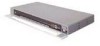
P74291ea_F1DExxxC.qxd 30-10-2003 13:56 Page 2 En OmniView™ KVM Switch with Micro-Cabling Technology Control up to 16 servers from up to two consoles Quick Installation Guide ENTERPRISE Quad-Bus Series F1DE108C F1DE116C F1DE208C F1DE216C
P74291ea_F1DExxxC.qxd 30-10-2003 13:56 Page 2 En OmniView™ KVM Switch with Micro-Cabling Technology Control up to 16 servers from up to two consoles Quick Installation Guide ENTERPRISE Quad-Bus Series F1DE108C F1DE116C F1DE208C F1DE216C

User Manual
Page 3
... will be used in a daisy-chained configuration. P74291ea_F1DExxxC.qxd 30-10-2003 13:56 Page 4 OmniView™ ENTERPRISE Quad-Bus Series KVM Switch with Micro-cabling Technology Quick Installation Guide Note: All diagrams show 2x16 model. If the unit will be used in a single-unit configuration or in a daisy-chained configuration...
... will be used in a daisy-chained configuration. P74291ea_F1DExxxC.qxd 30-10-2003 13:56 Page 4 OmniView™ ENTERPRISE Quad-Bus Series KVM Switch with Micro-cabling Technology Quick Installation Guide Note: All diagrams show 2x16 model. If the unit will be used in a single-unit configuration or in a daisy-chained configuration...

User Manual
Page 4
Hosts 1 & 2 Hosts 3 & 4 Hosts 1 & 2 Hosts 3 & 4 Hosts 5 & 6 Hosts 7 & 8 USB connection STEP 6: Connect the other end of the KVM Cable to the Switch (Belkin part number F1D9400-XX or F1D9401-XX). Hosts 1 & 2 Hosts 3 & 4 Hosts 5 & 6 Hosts 7 & 8 STEP 8: Power up the unit. Check for keyboard, video, and mouse function. P74291ea_F1DExxxC.qxd ...
Hosts 1 & 2 Hosts 3 & 4 Hosts 1 & 2 Hosts 3 & 4 Hosts 5 & 6 Hosts 7 & 8 USB connection STEP 6: Connect the other end of the KVM Cable to the Switch (Belkin part number F1D9400-XX or F1D9401-XX). Hosts 1 & 2 Hosts 3 & 4 Hosts 5 & 6 Hosts 7 & 8 STEP 8: Power up the unit. Check for keyboard, video, and mouse function. P74291ea_F1DExxxC.qxd ...
User Manual
Page 5
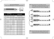
... 09 SECONDARY BANK 10 SECONDARY BANK 11 SECONDARY BANK 12 SECONDARY BANK 13 SECONDARY BANK 14 SECONDARY BANK 15 SECONDARY STEP 2: Attach the Daisy-Chain Cable (Belkin part number F1D9402-XX) to an available daisy-chain port of the previous Switch, making sure that the Daisy-Chain...
... 09 SECONDARY BANK 10 SECONDARY BANK 11 SECONDARY BANK 12 SECONDARY BANK 13 SECONDARY BANK 14 SECONDARY BANK 15 SECONDARY STEP 2: Attach the Daisy-Chain Cable (Belkin part number F1D9402-XX) to an available daisy-chain port of the previous Switch, making sure that the Daisy-Chain...
User Manual
Page 6
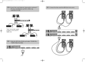
... 1 & 2 Hosts 3 & 4 Hosts 5 & 6 Hosts 7 & 8 Hosts 1 & 2 Hosts 3 & 4 Hosts 5 & 6 Hosts 7 & 8 *Note: Dual-console support available on 2x8 and 2x16 models only Hosts 1 & 2 Hosts 3 & 4 Hosts 5 STEP 5: Attach the KVM Cables (Belkin part number F1D9400-XX or F1D9401-XX) to the server. P74291ea_F1DExxxC.qxd 30-10-2003 13:56 Page 10 STEP 4: Connect the console keyboard, video... monitor, and mouse.* (For mouse and keyboard, use PS/2 or USB or any combination of both.) STEP 6: Connect the other end of the KVM Cable to the Switch.
... 1 & 2 Hosts 3 & 4 Hosts 5 & 6 Hosts 7 & 8 Hosts 1 & 2 Hosts 3 & 4 Hosts 5 & 6 Hosts 7 & 8 *Note: Dual-console support available on 2x8 and 2x16 models only Hosts 1 & 2 Hosts 3 & 4 Hosts 5 STEP 5: Attach the KVM Cables (Belkin part number F1D9400-XX or F1D9401-XX) to the server. P74291ea_F1DExxxC.qxd 30-10-2003 13:56 Page 10 STEP 4: Connect the console keyboard, video... monitor, and mouse.* (For mouse and keyboard, use PS/2 or USB or any combination of both.) STEP 6: Connect the other end of the KVM Cable to the Switch.

User Manual
Page 7
...; 90220 • USA Tel: 310.898.1100 Fax: 310.898.1111 Belkin Components, Ltd. P74291 Guide d'installation rapide Série Quad-Bus ENTREPRISE F1DE108C F1DE116C F1DE208C F1DE216C P74291ea_F1DExxxC.qxd 30-10-2003 13:56 Page 12 STEP 7: Connect the IEC power cable to the Switch and power up the connected servers. Express Business...
...; 90220 • USA Tel: 310.898.1100 Fax: 310.898.1111 Belkin Components, Ltd. P74291 Guide d'installation rapide Série Quad-Bus ENTREPRISE F1DE108C F1DE116C F1DE208C F1DE216C P74291ea_F1DExxxC.qxd 30-10-2003 13:56 Page 12 STEP 7: Connect the IEC power cable to the Switch and power up the connected servers. Express Business...
