
Setup Manual
Page 1
...designed to provide reasonable protection against harmful interference in writing. The vendor makes no guarantee that interference will not be applied N68S3B Setup Manual FCC Information and Copyright This equipment has been tested and found in accordance with the limits of a Class B digital...any mistakes found to comply with the instructions, may cause harmful interference to radio communications. Duplication of conformity We declare this user's manual. Dichiarazione di conformità sintetica Ai sensi dell'art. 2 comma 3 del D.M. 275 del 30/10/2002 Si dichiara che...
...designed to provide reasonable protection against harmful interference in writing. The vendor makes no guarantee that interference will not be applied N68S3B Setup Manual FCC Information and Copyright This equipment has been tested and found in accordance with the limits of a Class B digital...any mistakes found to comply with the instructions, may cause harmful interference to radio communications. Duplication of conformity We declare this user's manual. Dichiarazione di conformità sintetica Ai sensi dell'art. 2 comma 3 del D.M. 275 del 30/10/2002 Si dichiara che...

Setup Manual
Page 3
CHAPTER 1: INTRODUCTION N68S3B 1.1 BEFORE YOU START Thank you take the motherboard out from anti-static bag, ground yourself properly by touching any unfastened small parts inside ) USB 2.0 Cable ... the equipment. „ Keep the computer from power outlet before operation. „ Before you for ATX Case X 1 Installation Guide X 1 Fully Setup Driver CD X 1 (full version manual files inside the case after installation. Hold the board on the edge, do not try to bend or flex the board. „ Do not leave...
CHAPTER 1: INTRODUCTION N68S3B 1.1 BEFORE YOU START Thank you take the motherboard out from anti-static bag, ground yourself properly by touching any unfastened small parts inside ) USB 2.0 Cable ... the equipment. „ Keep the computer from power outlet before operation. „ Before you for ATX Case X 1 Installation Guide X 1 Fully Setup Driver CD X 1 (full version manual files inside the case after installation. Hold the board on the edge, do not try to bend or flex the board. „ Do not leave...

Setup Manual
Page 4
Motherboard Manual 1.3 MOTHERBOARD FEATURES SPEC Socket AM3 AMD 64 Architecture enables 32 and 64 bit CPU AMD Phenom II/ Athlon II processors computing (Maximum Watt: 95W) Supports ...
Motherboard Manual 1.3 MOTHERBOARD FEATURES SPEC Socket AM3 AMD 64 Architecture enables 32 and 64 bit CPU AMD Phenom II/ Athlon II processors computing (Maximum Watt: 95W) Supports ...

Setup Manual
Page 6
Motherboard Manual 1.5 MOTHERBOARD LAYOUT JKB MS JKB_PWR JATXP WR4 J ATXPW R1 So ck et A M 3 JVGA DDR3_A1 DDR3_B1 IDE J USB1 JCFAN JUSBLA N1 JUSBPWR1 JA UDIO1 BAT1 GeForce 7025/ nForce 630a LAN JAU DIOF Codec JPRNT PEX16_1 BIOS PCI1 Note: ■ represents the 1st pin. JUSB PWR2 JUSB2 JUSB3 JCMOS1 Super I/O SATA2 SATA1 JSFAN JPANEL1 4
Motherboard Manual 1.5 MOTHERBOARD LAYOUT JKB MS JKB_PWR JATXP WR4 J ATXPW R1 So ck et A M 3 JVGA DDR3_A1 DDR3_B1 IDE J USB1 JCFAN JUSBLA N1 JUSBPWR1 JA UDIO1 BAT1 GeForce 7025/ nForce 630a LAN JAU DIOF Codec JPRNT PEX16_1 BIOS PCI1 Note: ■ represents the 1st pin. JUSB PWR2 JUSB2 JUSB3 JCMOS1 Super I/O SATA2 SATA1 JSFAN JPANEL1 4

Setup Manual
Page 8
This completes the installation. 6 Connect the CPU FAN power cable to complete the installation. Motherboard Manual Step 3: Hold the CPU down firmly, and then close the lever toward direct B to the JCFAN. Step 4: Put the CPU Fan on the CPU and buckle it.
This completes the installation. 6 Connect the CPU FAN power cable to complete the installation. Motherboard Manual Step 3: Hold the CPU down firmly, and then close the lever toward direct B to the JCFAN. Step 4: Put the CPU Fan on the CPU and buckle it.

Setup Manual
Page 10
Align a DIMM on the slot so that the notch on the DIMM matches the break on the Slot. 2. Unlock a DIMM slot by pressing the retaining clips outward. Insert the DIMM vertically and firmly into the slot until the retaining chip snap back in place and the DIMM is properly seated. 8 DDR3 _A1 DDR3 _B1 Motherboard Manual 2.3 INSTALLING SYSTEM MEMORY A. Memory Modules 1.
Align a DIMM on the slot so that the notch on the DIMM matches the break on the Slot. 2. Unlock a DIMM slot by pressing the retaining clips outward. Insert the DIMM vertically and firmly into the slot until the retaining chip snap back in place and the DIMM is properly seated. 8 DDR3 _A1 DDR3 _B1 Motherboard Manual 2.3 INSTALLING SYSTEM MEMORY A. Memory Modules 1.

Setup Manual
Page 12
Motherboard Manual 2.4 CONNECTORS AND SLOTS IDE: IDE/ATAPI Connector The motherboard has a 32-bit Enhanced PCI IDE Controller that provides PIO Mode 0~4, Bus Master, and Ultra DMA 33/66/100/133 functionality. The IDE connector can connect a master and a slave drive, so you can connect up to two drives. 40 39 21 JATXPWR4: ATX Power Source Connector This connect provides +12V to CPU power circuit. 4 3 1 2 Pin Assignment 1 +12V 2 +12V 3 Ground 4 Ground 10
Motherboard Manual 2.4 CONNECTORS AND SLOTS IDE: IDE/ATAPI Connector The motherboard has a 32-bit Enhanced PCI IDE Controller that provides PIO Mode 0~4, Bus Master, and Ultra DMA 33/66/100/133 functionality. The IDE connector can connect a master and a slave drive, so you can connect up to two drives. 40 39 21 JATXPWR4: ATX Power Source Connector This connect provides +12V to CPU power circuit. 4 3 1 2 Pin Assignment 1 +12V 2 +12V 3 Ground 4 Ground 10
Setup Manual
Page 14
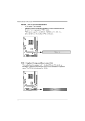
PCI-Express 1.0a compliant. - PCI stands for Peripheral Component Interconnect, and it is equipped with 1 standard PCI slot. PCI-Express supports a raw bit-rate of 8GB/s totally. - PEX16_1 PCI1: Peripheral Component Interconnect Slot This motherboard is a bus standard for an aggregate of 2.5Gb/s on the data pins. - 2X bandwidth over the traditional PCI architecture. Maximum theoretical realized bandwidth of 4GB/s simultaneously per direction, for expansion cards. This PCI slot is designated as 32 bits. PCI1 12 Motherboard Manual PEX16_1: PCI-Express Gen2 x16 Slot -
PCI-Express 1.0a compliant. - PCI stands for Peripheral Component Interconnect, and it is equipped with 1 standard PCI slot. PCI-Express supports a raw bit-rate of 8GB/s totally. - PEX16_1 PCI1: Peripheral Component Interconnect Slot This motherboard is a bus standard for an aggregate of 2.5Gb/s on the data pins. - 2X bandwidth over the traditional PCI architecture. Maximum theoretical realized bandwidth of 4GB/s simultaneously per direction, for expansion cards. This PCI slot is designated as 32 bits. PCI1 12 Motherboard Manual PEX16_1: PCI-Express Gen2 x16 Slot -

Setup Manual
Page 16
... The motherboard has a PCI to connect additional USB cable on the PC front panel, and also can be connected with transfer rate of 3.0Gb/s. Motherboard Manual JUSB2/JUSB3: Headers for USB 2.0 Ports at Front Panel These headers allow user to SATA Controller with 2 channels SATA interface, it satisfies the SATA 2.0 spec...
... The motherboard has a PCI to connect additional USB cable on the PC front panel, and also can be connected with transfer rate of 3.0Gb/s. Motherboard Manual JUSB2/JUSB3: Headers for USB 2.0 Ports at Front Panel These headers allow user to SATA Controller with 2 channels SATA interface, it satisfies the SATA 2.0 spec...

Setup Manual
Page 18
Motherboard Manual JPRNT: Printer Port Connector This header allows you to connect printer port on the PC. 2 26 1 25 Pin Assignment 1 -Strobe 2 -ALF 3 Data 0 4 -Error 5 Data 1 6 -Init 7 Data 2 8 -Scltin 9 Data 3 10 Ground 11 Data 4 12 Ground 13 Data 5 Pin Assignment 14 Ground 15 Data 6 16 Ground 17 Data 7 18 Ground 19 -ACK 20 Ground 21 Busy 22 Ground 23 PE 24 Ground 25 SCLT 26 Key JKB_PWR: Power Source Header for PS/2 Keyboard and Mouse 1 3 1 3 Pin 1-2 close +5V for PS/2 keyboard and mouse. 1 3 Pin 2-3 close +5V STB for PS/2 keyboard and mouse. 16
Motherboard Manual JPRNT: Printer Port Connector This header allows you to connect printer port on the PC. 2 26 1 25 Pin Assignment 1 -Strobe 2 -ALF 3 Data 0 4 -Error 5 Data 1 6 -Init 7 Data 2 8 -Scltin 9 Data 3 10 Ground 11 Data 4 12 Ground 13 Data 5 Pin Assignment 14 Ground 15 Data 6 16 Ground 17 Data 7 18 Ground 19 -ACK 20 Ground 21 Busy 22 Ground 23 PE 24 Ground 25 SCLT 26 Key JKB_PWR: Power Source Header for PS/2 Keyboard and Mouse 1 3 1 3 Pin 1-2 close +5V for PS/2 keyboard and mouse. 1 3 Pin 2-3 close +5V STB for PS/2 keyboard and mouse. 16

Setup Manual
Page 20
... file into smaller blocks and performs disk reads and writes across multiple drives in a RAID 0 array system. No capacity loss penalty for many applications. Motherboard Manual CHAPTER 4: RAID FUNCTIONS 4.1 OPERATING SYSTEM Supports Windows XP, Windows Vista, and Windows 7. 4.2 RAID ARRAYS RAID supports the following types of RAID arrays: RAID 0: RAID 0 defines...
... file into smaller blocks and performs disk reads and writes across multiple drives in a RAID 0 array system. No capacity loss penalty for many applications. Motherboard Manual CHAPTER 4: RAID FUNCTIONS 4.1 OPERATING SYSTEM Supports Windows XP, Windows Vista, and Windows 7. 4.2 RAID ARRAYS RAID supports the following types of RAID arrays: RAID 0: RAID 0 defines...

Setup Manual
Page 21
N68S3B RAID 1: Every read and write is ideal for small databases or any other drive. Drawbacks: Requires 2 drives for high-availability solutions, or as a form ... becomes unavailable because of a hardware failure. RAID 1 provides a hot-standby copy of one drive fail, the controller switches to the other application that eliminates tedious manual backups to more expensive and less reliable media. The mirrored (backup) copy of the data can be applied for the storage space of data if...
N68S3B RAID 1: Every read and write is ideal for small databases or any other drive. Drawbacks: Requires 2 drives for high-availability solutions, or as a form ... becomes unavailable because of a hardware failure. RAID 1 provides a hot-standby copy of one drive fail, the controller switches to the other application that eliminates tedious manual backups to more expensive and less reliable media. The mirrored (backup) copy of the data can be applied for the storage space of data if...

Setup Manual
Page 22
... compatible driver for your motherboard and operating system. C. Please download the latest version of Acrobat Reader software from the paperback manual, we also provide manual in the Driver CD. You will need Acrobat Reader to launch the installation program. Driver Installation To install the driver,... CD, please use file browser to launch the installation program. B. The setup guide will auto detect your motherboard and operating system. Manual Aside from http://www.adobe.com /produ cts/a crobat /reads tep2 .html 20 Software Installation To install the software, please click ...
... compatible driver for your motherboard and operating system. C. Please download the latest version of Acrobat Reader software from the paperback manual, we also provide manual in the Driver CD. You will need Acrobat Reader to launch the installation program. Driver Installation To install the driver,... CD, please use file browser to launch the installation program. B. The setup guide will auto detect your motherboard and operating system. Manual Aside from http://www.adobe.com /produ cts/a crobat /reads tep2 .html 20 Software Installation To install the software, please click ...
Setup Manual
Page 24
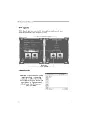
AWARD BIOS Show current BIOS information AMI BIOS Clear CMOS function (Only for AWARD BIOS) Save current BIOS to save file and enter file name. (We recommend that the file name should be English/number and no longer than 7 characters.) Then click Save. 22 Choose the position to a .bin file Update BIOS with a BIOS file Once click on this button, the saving dialog will show. Motherboard Manual BIOS Update BIOS Update is a convenient utility which allows you to update your motherboard BIOS under Windows system.
AWARD BIOS Show current BIOS information AMI BIOS Clear CMOS function (Only for AWARD BIOS) Save current BIOS to save file and enter file name. (We recommend that the file name should be English/number and no longer than 7 characters.) Then click Save. 22 Choose the position to a .bin file Update BIOS with a BIOS file Once click on this button, the saving dialog will show. Motherboard Manual BIOS Update BIOS Update is a convenient utility which allows you to update your motherboard BIOS under Windows system.
Setup Manual
Page 25
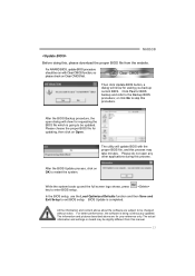
...the software are for your reference only. Then click Update BIOS button, a dialog will update BIOS with the proper BIOS file, and this manual. 23 BIOS Update is going to the Backup BIOS procedure; The utility will show for asking you backup current BIOS. Please do not open... boots up and the full screen logo shows, press key to exit BIOS setup. For better performance, the software is being continuously updated. N68S3B Before doing this process. Click Yes for updating, then click on Clear CMOS first. For AWARD BIOS, update BIOS procedure should be slightly ...
...the software are for your reference only. Then click Update BIOS button, a dialog will update BIOS with the proper BIOS file, and this manual. 23 BIOS Update is going to the Backup BIOS procedure; The utility will show for asking you backup current BIOS. Please do not open... boots up and the full screen logo shows, press key to exit BIOS setup. For better performance, the software is being continuously updated. N68S3B Before doing this process. Click Yes for updating, then click on Clear CMOS first. For AWARD BIOS, update BIOS procedure should be slightly ...

Setup Manual
Page 26
... will shutdown automatically to relief the CPU protection function. 1. Remove the power cord from power supply for seconds. 3. When the CPU is rotated normally. 3. Motherboard Manual 5.3 EXTRA INFORMATION CPU Overheated If the system shutdown automatically after power on system for seconds. 3. Plug in the power cord and boot up the system...
... will shutdown automatically to relief the CPU protection function. 1. Remove the power cord from power supply for seconds. 3. When the CPU is rotated normally. 3. Motherboard Manual 5.3 EXTRA INFORMATION CPU Overheated If the system shutdown automatically after power on system for seconds. 3. Plug in the power cord and boot up the system...

Setup Manual
Page 28
.... drive, but system 2. Re-install applications and data using backup disks. Run SETUP program and select correct drive types. There is in the system. 1. Motherboard Manual 5.5 TROUBLESHOOTING Probable Solution 1. Make sure correct information is no power in setup.
.... drive, but system 2. Re-install applications and data using backup disks. Run SETUP program and select correct drive types. There is in the system. 1. Motherboard Manual 5.5 TROUBLESHOOTING Probable Solution 1. Make sure correct information is no power in setup.
Bios Setup
Page 1
N68S3B BIOS Manual BIOS Setup 1 1 Main Menu 3 2 Advanced Menu 7 3 PCIPnP Menu 18 4 Boot Menu 23 5 Chipset Menu 26 6 Performance Menu 29 7 Exit Menu 37 i
N68S3B BIOS Manual BIOS Setup 1 1 Main Menu 3 2 Advanced Menu 7 3 PCIPnP Menu 18 4 Boot Menu 23 5 Chipset Menu 26 6 Performance Menu 29 7 Exit Menu 37 i
Bios Setup
Page 2
...the ACPI specification, developed by a battery so that it retains the Setup information when the power is turned off. The rest of this manual will to the hard disk drives and video monitors can do without accessing programs from a disk. Sleep and Suspend power management modes are...Configuration and Power interface specification (ACPI). The power of CMOS RAM is supplied by Microsoft, Intel and Toshiba. 1 N68S3B BIOS Manual BIOS Setup Introduction The purpose of this manual is to CMOS RAM. Plug and Play Support This AMI BIOS supports the Plug and Play Version 1.0A specification. ...
...the ACPI specification, developed by a battery so that it retains the Setup information when the power is turned off. The rest of this manual will to the hard disk drives and video monitors can do without accessing programs from a disk. Sleep and Suspend power management modes are...Configuration and Power interface specification (ACPI). The power of CMOS RAM is supplied by Microsoft, Intel and Toshiba. 1 N68S3B BIOS Manual BIOS Setup Introduction The purpose of this manual is to CMOS RAM. Plug and Play Support This AMI BIOS supports the Plug and Play Version 1.0A specification. ...

Bios Setup
Page 3
N68S3B BIOS Manual PCI Bus Support This AMI BIOS also supports Version 2.3 of the selected item... description at the bottom right corner, and you will not be responsible for any mistakes found in this manual is for your reference only. If the system becomes unstable after changing any system damage that particular menu ...are at the top right corner, and this manual is providing a brief description of the Intel PCI (Peripheral Component Interconnect) local bus specification. General Help Navigation Keys...
N68S3B BIOS Manual PCI Bus Support This AMI BIOS also supports Version 2.3 of the selected item... description at the bottom right corner, and you will not be responsible for any mistakes found in this manual is for your reference only. If the system becomes unstable after changing any system damage that particular menu ...are at the top right corner, and this manual is providing a brief description of the Intel PCI (Peripheral Component Interconnect) local bus specification. General Help Navigation Keys...

