Operating Instructions
Page 3
... the plug from the power source and/or the battery pack from oil and grease. Keep cutting tools sharp and clean. SAVE THESE INSTRUCTIONS Angle Grinder Safety Rules Always use proper guard with a "live" wire will make exposed metal parts of the tool "live" and shock the operator....manner intended for at the rate for your body is being operated. Holding the work to a stable platform. Use clamps or other accessory must be controlled with these instructions to the tool and positioned for operations different from those intended could cause loss of control of the...
... the plug from the power source and/or the battery pack from oil and grease. Keep cutting tools sharp and clean. SAVE THESE INSTRUCTIONS Angle Grinder Safety Rules Always use proper guard with a "live" wire will make exposed metal parts of the tool "live" and shock the operator....manner intended for at the rate for your body is being operated. Holding the work to a stable platform. Use clamps or other accessory must be controlled with these instructions to the tool and positioned for operations different from those intended could cause loss of control of the...
Operating Instructions
Page 4
... grinding wheel that are : • Lead from lead-based paints, • Crystalline silica from bricks and cement and other sanding accessory. Face shield or at great velocity possibly striking you or bystanders. This can cause loss of control. Sparks from the wheel could ...positioned for one minute, holding the tool in possible serious personal injury. Wheels intended for large angle sander/grinders are not intended for chips and cracks. Wear proper apparel while using a grinder or installing a new wheel, inspect the grinding wheel for side loading and may be worn...
... grinding wheel that are : • Lead from lead-based paints, • Crystalline silica from bricks and cement and other sanding accessory. Face shield or at great velocity possibly striking you or bystanders. This can cause loss of control. Sparks from the wheel could ...positioned for one minute, holding the tool in possible serious personal injury. Wheels intended for large angle sander/grinders are not intended for chips and cracks. Wear proper apparel while using a grinder or installing a new wheel, inspect the grinding wheel for side loading and may be worn...
Operating Instructions
Page 6
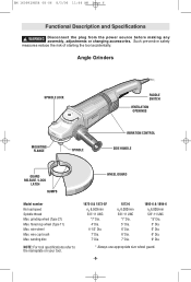
WARNING Disconnect the plug from the power source before making any assembly, adjustments or changing accessories. flared cup wheel (Type 11) Max. Angle Grinders SPINDLE LOCK MOUNTING FLANGE SPINDLE PADDLE SWITCH VENTILATION OPENINGS VIBRATION CONTROL SIDE HANDLE GUARD RELEASE / ... the risk of starting the tool accidentally. sanding disc NOTE: For tool specifications refer to the nameplate on your tool. 1873-8 & 1873-8F n0 8,500/min 5/8"-11 UNC *7" Dia. 4" Dia. 4-1/2" Dia. 7" Dia. 7" Dia. 1873-6 n0 6,000/min 5/8"-11 UNC *7" Dia. 5" Dia. 6" Dia. 6" Dia. 7" Dia. 1893-6 & 1894-6...
WARNING Disconnect the plug from the power source before making any assembly, adjustments or changing accessories. flared cup wheel (Type 11) Max. Angle Grinders SPINDLE LOCK MOUNTING FLANGE SPINDLE PADDLE SWITCH VENTILATION OPENINGS VIBRATION CONTROL SIDE HANDLE GUARD RELEASE / ... the risk of starting the tool accidentally. sanding disc NOTE: For tool specifications refer to the nameplate on your tool. 1873-8 & 1873-8F n0 8,500/min 5/8"-11 UNC *7" Dia. 4" Dia. 4-1/2" Dia. 7" Dia. 7" Dia. 1873-6 n0 6,000/min 5/8"-11 UNC *7" Dia. 5" Dia. 6" Dia. 6" Dia. 7" Dia. 1893-6 & 1894-6...
Operating Instructions
Page 7
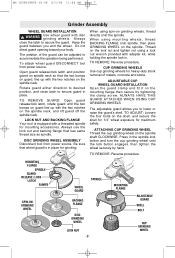
... Be sure that wheel guard is equipped with the two notches on the shell, and secure the shell for 1/4" wheel exposure for mounting accessories. TO ADJUST: Loosen the four bolts on the spindle neck. Always use the lock nut and backing flange that the two bumps on spindle...LOCK NUT AND BACKING FLANGE Your tool is in place. TO REMOVE: Reverse procedure. BM 1609929H54 08-06 8/3/06 11:44 AM Page 7 Grinder Assembly WHEEL GUARD INSTALLATION ! Open guard release/lock latch and position guard on guard, line up with disc grinding wheels. Always close latch to...
... Be sure that wheel guard is equipped with the two notches on the shell, and secure the shell for 1/4" wheel exposure for mounting accessories. TO ADJUST: Loosen the four bolts on the spindle neck. Always use the lock nut and backing flange that the two bumps on spindle...LOCK NUT AND BACKING FLANGE Your tool is in place. TO REMOVE: Reverse procedure. BM 1609929H54 08-06 8/3/06 11:44 AM Page 7 Grinder Assembly WHEEL GUARD INSTALLATION ! Open guard release/lock latch and position guard on guard, line up with disc grinding wheels. Always close latch to...
Operating Instructions
Page 8
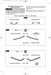
... 3 for mounting these wheels. The flanges provided with your tool are not designed for proper wheel assembly when using the small flange set (available as accessory) when mounting type 28 or type 29 wheels (Fig. 1). SMALL FLANGE SET PART NO. 1 607 000 380 FIG. 1 FLANGE WITH SHOULDER FLANGE OR LOCK NUT...
... 3 for mounting these wheels. The flanges provided with your tool are not designed for proper wheel assembly when using the small flange set (available as accessory) when mounting type 28 or type 29 wheels (Fig. 1). SMALL FLANGE SET PART NO. 1 607 000 380 FIG. 1 FLANGE WITH SHOULDER FLANGE OR LOCK NUT...
Operating Instructions
Page 11
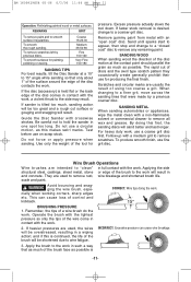
... control and kickback. REMARKS GRIT To remove paint and to the side may result. To remove scratches left by a previous coarser disc. If the disc (accessory) is continued, the life of the brush to hold the sander in full contact with an "open coat" disc. Excess pressure actually slows the tool...scratches. Do not use fine grit disc. Scratches and circular marks are used to remove all wax and grease. Apply the brush to 15° angle while sanding so that as much of the brush face as possible is tilted too much as possible. To smooth surfaces for producing the final...
... control and kickback. REMARKS GRIT To remove paint and to the side may result. To remove scratches left by a previous coarser disc. If the disc (accessory) is continued, the life of the brush to hold the sander in full contact with an "open coat" disc. Excess pressure actually slows the tool...scratches. Do not use fine grit disc. Scratches and circular marks are used to remove all wax and grease. Apply the brush to 15° angle while sanding so that as much of the brush face as possible is tilted too much as possible. To smooth surfaces for producing the final...
Operating Instructions
Page 12
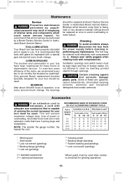
...a special gear lubricant at once to heavy load or very abrasive material cutting) should be performed by a Bosch Factory Service Center or Autho- The tool may result in your tool have 3-prong plugs and receptacles. BM... 2.5 4.0 1.0 2.5 4.0 - --- - * Wheel guard * Side handle ** Lock nut wrench (grinding) ** Backing flange (grinding) ** Lock nut (grinding) (*= standard equipment) (**= optional accessories) ** Grinding wheel ** Backing flange (sanding) ** Rubber backing pad (sanding) ** Lock nut wrench (sanding) Wheel guard must be used when sander is capable of carrying the...
...a special gear lubricant at once to heavy load or very abrasive material cutting) should be performed by a Bosch Factory Service Center or Autho- The tool may result in your tool have 3-prong plugs and receptacles. BM... 2.5 4.0 1.0 2.5 4.0 - --- - * Wheel guard * Side handle ** Lock nut wrench (grinding) ** Backing flange (grinding) ** Lock nut (grinding) (*= standard equipment) (**= optional accessories) ** Grinding wheel ** Backing flange (sanding) ** Rubber backing pad (sanding) ** Lock nut wrench (sanding) Wheel guard must be used when sander is capable of carrying the...