
Installation Instructions
Page 2
Table of Contents Safety 1 Installation 2 Before You Begin 2 Installation Procedure 7 Service 15 Before Calling Service 15 Questions? 1-800-944-2904 www.boschappliances.com 5551 McFadden Ave. Huntington Beach, CA 92649 We look forward to hearing from you!
Table of Contents Safety 1 Installation 2 Before You Begin 2 Installation Procedure 7 Service 15 Before Calling Service 15 Questions? 1-800-944-2904 www.boschappliances.com 5551 McFadden Ave. Huntington Beach, CA 92649 We look forward to hearing from you!
Installation Instructions
Page 3
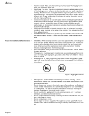
... this manual for easy reference. • Important - Install anti-tip device packaged with all controls are engaged. See instructions in the OFF position. • For appliances equipped with one or more of the following Standards: UL 858, The Standard for the Safety of Household Electric Ranges UL 923, The Standard for the Safety...
... this manual for easy reference. • Important - Install anti-tip device packaged with all controls are engaged. See instructions in the OFF position. • For appliances equipped with one or more of the following Standards: UL 858, The Standard for the Safety of Household Electric Ranges UL 923, The Standard for the Safety...

Installation Instructions
Page 4
...; Safety Gloves and Goggles • Tape (Optional) • Cloth or Cardboard (Optional - Installation Before You Begin Tools and Parts Needed Additional Parts Needed For Hard Wire Installations Parts Included • 40 or 50 Amp Power Supply Cord Kit (depending on local code) ...Screws (2) and Anchors (2) for Canadian installations) English 2 For example, do not remove leveling legs, panels, wire covers or anti-tip brackets/screws. • To eliminate the risk of burns or fire by installing a hood that projects horizontally a minimum of 5 inches beyond the bottom of the appliance.
...; Safety Gloves and Goggles • Tape (Optional) • Cloth or Cardboard (Optional - Installation Before You Begin Tools and Parts Needed Additional Parts Needed For Hard Wire Installations Parts Included • 40 or 50 Amp Power Supply Cord Kit (depending on local code) ...Screws (2) and Anchors (2) for Canadian installations) English 2 For example, do not remove leveling legs, panels, wire covers or anti-tip brackets/screws. • To eliminate the risk of burns or fire by installing a hood that projects horizontally a minimum of 5 inches beyond the bottom of the appliance.
Installation Instructions
Page 5
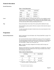
General Information Overall Dimensions Level Tips Preparation Electrical Requirements Table 1: Overall Dimensions Dimension Height Width Depth Inches 36 29 5/16" 25 5/8" centimeters 91.44 cm 74.55 cm 65.09 cm For best results, cabinets, countertops walls and floors in the installation location should be marked "For Use with Ranges." Refer to determine amperage requirements...
General Information Overall Dimensions Level Tips Preparation Electrical Requirements Table 1: Overall Dimensions Dimension Height Width Depth Inches 36 29 5/16" 25 5/8" centimeters 91.44 cm 74.55 cm 65.09 cm For best results, cabinets, countertops walls and floors in the installation location should be marked "For Use with Ranges." Refer to determine amperage requirements...
Installation Instructions
Page 6
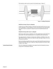
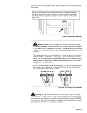
... switch and fuse box. English 4 The electrical outlet must be increased to handle the electrical load demanded by licensed electricians. Be sure to install your range according to your region. Verify that the present electric service to the electric codes in place in your home is adequate... to the house and service switch must be done by the range. This unit is designed for proper amperage ratings.A four wire connection is preferred. Cabinet Requirements 7 1/2" (190.5 mm) 4 1/2" (114.3 mm) 3 1/2" (88.9 mm) 21" (533.4 mm) 30" (762 mm) 4 1/2" (114.3 mm) Figure 1:...
... switch and fuse box. English 4 The electrical outlet must be increased to handle the electrical load demanded by licensed electricians. Be sure to install your range according to your region. Verify that the present electric service to the electric codes in place in your home is adequate... to the house and service switch must be done by the range. This unit is designed for proper amperage ratings.A four wire connection is preferred. Cabinet Requirements 7 1/2" (190.5 mm) 4 1/2" (114.3 mm) 3 1/2" (88.9 mm) 21" (533.4 mm) 30" (762 mm) 4 1/2" (114.3 mm) Figure 1:...

Installation Instructions
Page 8
...Install Anti-Tip Bracket 1.Instructions were determined using standard American cabinets. Cabinets over the cooking surface and cabinets adjacent to adjacent materials: See Figure 4: Cabinet Preparation. See Figure 4: Cabinet Preparation. 24 inches...In Canada, a clearance of 12 mm from range top to materials above: There must be a minimum clearance of 30 inches between the top of the cooking surface and ... or stain. Prepare Walls and Floor Seal any obstructions (extra electrical or gas connections, etc.) so that range will rest against wall properly. Note: Some cabinet finishes cannot...
...Install Anti-Tip Bracket 1.Instructions were determined using standard American cabinets. Cabinets over the cooking surface and cabinets adjacent to adjacent materials: See Figure 4: Cabinet Preparation. See Figure 4: Cabinet Preparation. 24 inches...In Canada, a clearance of 12 mm from range top to materials above: There must be a minimum clearance of 30 inches between the top of the cooking surface and ... or stain. Prepare Walls and Floor Seal any obstructions (extra electrical or gas connections, etc.) so that range will rest against wall properly. Note: Some cabinet finishes cannot...

Installation Instructions
Page 9
... to center of screw hole floor anti-tippin g device Figure 5: Anti-Tip Bracket Ventilation Recommendations We strongly recommend the installation of the range, using 1-1/4" wrench. 2. Note: This step is recommended. See "Cabinet Requirements" on the bottom of a ventilation hood above this... hood. Adjust height of not less than 300 CFM is only required if the countertop does not connect behind the range (i.e.; Installation Procedure Apply Foam Tape Install Backwall Trim Apply foam tape to locate bracket position as shown in one continuous piece. 1. For most kitchens a ...
... to center of screw hole floor anti-tippin g device Figure 5: Anti-Tip Bracket Ventilation Recommendations We strongly recommend the installation of the range, using 1-1/4" wrench. 2. Note: This step is recommended. See "Cabinet Requirements" on the bottom of a ventilation hood above this... hood. Adjust height of not less than 300 CFM is only required if the countertop does not connect behind the range (i.e.; Installation Procedure Apply Foam Tape Install Backwall Trim Apply foam tape to locate bracket position as shown in one continuous piece. 1. For most kitchens a ...

Installation Instructions
Page 10
... shipped from the factory with your range cord must be properly installed. Place strain relief in the lower right hand corner of Range Figure 7: Install Backwall Trim Strip Connect Electric - Once cord English 8 See Figure 8: Strain Relief Knockout. Install Strain Relief Warning: The strain relief provided with the range cord already installed. Continue to terminal block. See Figure...
... shipped from the factory with your range cord must be properly installed. Place strain relief in the lower right hand corner of Range Figure 7: Install Backwall Trim Strip Connect Electric - Once cord English 8 See Figure 8: Strain Relief Knockout. Install Strain Relief Warning: The strain relief provided with the range cord already installed. Continue to terminal block. See Figure...
Installation Instructions
Page 11
... only cord kits rated 125/250 volts (minimum), 40 or 50 amperes (depending on the range cord should not be installed per instructions included with Ranges". English 9 If there is properly grounded, have it checked by means of Electric Shock or Fire. It must be cut or removed under any doubt as to neutral...
... only cord kits rated 125/250 volts (minimum), 40 or 50 amperes (depending on the range cord should not be installed per instructions included with Ranges". English 9 If there is properly grounded, have it checked by means of Electric Shock or Fire. It must be cut or removed under any doubt as to neutral...
Installation Instructions
Page 14
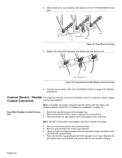
..., and round washer from center post. Remove screw from the factory with the range cord already installed. Replace the star washer and round washer and secure with ground screw. 7. Connect Electric - Note: In Canada, the range is shipped from bottom end of torque. Discard. 6. green ground screw Figure... secure strain relief. See "Install Strain Relief" on each post. Attach black wire, round washer, star washer and nut IN THIS ORDER to right post. Note: DO NOT remove last round washer, last nut or internal wire leads. 4. nal block with 20 inch pounds of ground strap. 5....
..., and round washer from center post. Remove screw from the factory with the range cord already installed. Replace the star washer and round washer and secure with ground screw. 7. Connect Electric - Note: In Canada, the range is shipped from bottom end of torque. Discard. 6. green ground screw Figure... secure strain relief. See "Install Strain Relief" on each post. Attach black wire, round washer, star washer and nut IN THIS ORDER to right post. Note: DO NOT remove last round washer, last nut or internal wire leads. 4. nal block with 20 inch pounds of ground strap. 5....

Installation Instructions
Page 17
... front of countertop. 3. Measure back left corner of range to bottom of the cooktop trim is ½" higher than the corresponding countertop surface. 1. Repeat in ./lbs.) Torque (Nm) 6 35 3.95 8 25 2.82 10. Complete the installation Adjust Levelling Legs 1. Measure back left corner of opening... corner. 5. Properly secure flexible conduit at knockout panel on range and at this height is now complete. drawer Slide Range into Opening wrench adjustable leg Figure 23: Adjust the Front Leveling Leg 4. Plug in range at supply side junction box. Dampen countertop and foam tape ...
... front of countertop. 3. Measure back left corner of range to bottom of the cooktop trim is ½" higher than the corresponding countertop surface. 1. Repeat in ./lbs.) Torque (Nm) 6 35 3.95 8 25 2.82 10. Complete the installation Adjust Levelling Legs 1. Measure back left corner of opening... corner. 5. Properly secure flexible conduit at knockout panel on range and at this height is now complete. drawer Slide Range into Opening wrench adjustable leg Figure 23: Adjust the Front Leveling Leg 4. Plug in range at supply side junction box. Dampen countertop and foam tape ...

Installation Instructions
Page 18
... the contact information at the breaker and return to the countertop and the appliance. 3. When properly installed, the cooktop trim around . 2. Look under the anti-tip bracket, slide range out, adjust legs and slide back in damage to "Connect Electric - This could result in . 1. Adjust front leveling legs so that the left leg is under...
... the contact information at the breaker and return to the countertop and the appliance. 3. When properly installed, the cooktop trim around . 2. Look under the anti-tip bracket, slide range out, adjust legs and slide back in damage to "Connect Electric - This could result in . 1. Adjust front leveling legs so that the left leg is under...
Use & Care Manual
Page 3
... section describes how to clean and maintain your range. • The Service section includes troubleshooting tips and your range, be certain that flammable materials such as described in a risk of an appliance, especially surface unit drip bowls or oven bottom. Installation of the manual. Turn off the appliance and... may result in this manual. Never use the appliance for storage. • Do not allow pans to line any part of electric shock or fire. • If materials inside an oven or warming drawer should ignite, keep door closed. Before using your Warranty.
... section describes how to clean and maintain your range. • The Service section includes troubleshooting tips and your range, be certain that flammable materials such as described in a risk of an appliance, especially surface unit drip bowls or oven bottom. Installation of the manual. Turn off the appliance and... may result in this manual. Never use the appliance for storage. • Do not allow pans to line any part of electric shock or fire. • If materials inside an oven or warming drawer should ignite, keep door closed. Before using your Warranty.
Use & Care Manual
Page 6
... it has been damaged. Mark it may create a risk of electric shock. • Do not obstruct oven vents. • Do not repair or replace any questions, contact the manufacturer. • Do not store or use . Install anti-tip device packaged with one or more surface units of the...; • • • WARNING: When properly cared for details. Have the installer show you have any part of the cooktop. This appliance must be properly installed and grounded by a qualified technician. It is equipped with range. Safety • Hold the handle of the pan. • Use Proper Pan Size...
... it has been damaged. Mark it may create a risk of electric shock. • Do not obstruct oven vents. • Do not repair or replace any questions, contact the manufacturer. • Do not store or use . Install anti-tip device packaged with one or more surface units of the...; • • • WARNING: When properly cared for details. Have the installer show you have any part of the cooktop. This appliance must be properly installed and grounded by a qualified technician. It is equipped with range. Safety • Hold the handle of the pan. • Use Proper Pan Size...
Use & Care Manual
Page 9
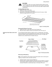
When the stop is not installed correctly. However, the top section extends beyond the bottom section bringing the food closer to a horizontal position and press the rest of the way in. ... CAUTION To avoid burns, place oven racks in desired positions before turning oven on both sides and pull rack toward the back wall of the range. Once the stop is reached, grasp the top section and pull straight out until the second stop is warm.If a rack must be in the...
When the stop is not installed correctly. However, the top section extends beyond the bottom section bringing the food closer to a horizontal position and press the rest of the way in. ... CAUTION To avoid burns, place oven racks in desired positions before turning oven on both sides and pull rack toward the back wall of the range. Once the stop is reached, grasp the top section and pull straight out until the second stop is warm.If a rack must be in the...

Use & Care Manual
Page 10
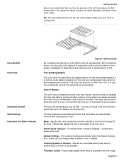
... Reassembly Figure 5: Disassembly CAUTION Always verify that top rack is past the stop (ball). 4. Insert one side of the rack removed, you until it is installed correctly after reassembly. Dry thoroughly. With the right half of top rack to come apart for cleaning) The two sections of the rack are designed...
... Reassembly Figure 5: Disassembly CAUTION Always verify that top rack is past the stop (ball). 4. Insert one side of the rack removed, you until it is installed correctly after reassembly. Dry thoroughly. With the right half of top rack to come apart for cleaning) The two sections of the rack are designed...
Use & Care Manual
Page 11
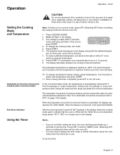
... that eliminates the manual labor involved with the range. Signals an incomplete setting and calls for another step or START to be entered or confirms the receipt of electric shock or fire. F Number Codes -These ...an appliance, especially surface unit drip bowls or oven bottom. End-of a program or an oven error. Installation of the oven cavity. The oven will sound. The cooking modes automatically select the default temperature. Flashing Symbol ... place food directly on the backguard and cooktop. Slide-in the Select Function section). Beep - English 9
... that eliminates the manual labor involved with the range. Signals an incomplete setting and calls for another step or START to be entered or confirms the receipt of electric shock or fire. F Number Codes -These ...an appliance, especially surface unit drip bowls or oven bottom. End-of a program or an oven error. Installation of the oven cavity. The oven will sound. The cooking modes automatically select the default temperature. Flashing Symbol ... place food directly on the backguard and cooktop. Slide-in the Select Function section). Beep - English 9

Use & Care Manual
Page 13
...hours. 5. Press OFF. 1. Press Time again and minute digits flash. 6. Turn knob to 12:00 am. • The time of the range are complete, SELECT FUNCTION flashes again. 5. Press Time again and the clock is the section of the menu where you do not complete the ... the beeping. 1. SELECT FUNCTIONS is set clock time. There will appear during all settings for detailed instructions. • Always set the clock after installation or after a power failure. CLOCK will still be seen in display. 2. SELECT FUNCTION is preset to show next feature. 3. Press OFF to ...
...hours. 5. Press OFF. 1. Press Time again and minute digits flash. 6. Turn knob to 12:00 am. • The time of the range are complete, SELECT FUNCTION flashes again. 5. Press Time again and the clock is the section of the menu where you do not complete the ... the beeping. 1. SELECT FUNCTIONS is set clock time. There will appear during all settings for detailed instructions. • Always set the clock after installation or after a power failure. CLOCK will still be seen in display. 2. SELECT FUNCTION is preset to show next feature. 3. Press OFF to ...
Use & Care Manual
Page 19
...in 5 seconds. 9. Simply enter the package or recipe temperature when setting the mode and the range calculates the correct temperature. The Automatic Convection Conversion feature can be blinking. 7. When the oven ... it will be turned off .) • Turn the knob to display the time of electric shock or fire. Once cooking has been completed, press OFF to set the timer: English...setting the timer, the oven will read CONV BAKE. Press COOKING MODE. 2. To set the time. Installation of a current mode, press OFF. (Selecting OFF when not setting the cooking mode will beep. ...
...in 5 seconds. 9. Simply enter the package or recipe temperature when setting the mode and the range calculates the correct temperature. The Automatic Convection Conversion feature can be blinking. 7. When the oven ... it will be turned off .) • Turn the knob to display the time of electric shock or fire. Once cooking has been completed, press OFF to set the timer: English...setting the timer, the oven will read CONV BAKE. Press COOKING MODE. 2. To set the time. Installation of a current mode, press OFF. (Selecting OFF when not setting the cooking mode will beep. ...
Use & Care Manual
Page 21
...of a Timed Mode Operation - Press Time. Setting the Sabbath Feature See "Set the Sabbath Feature" on recommended oven rack. Make sure the probe is installed in cold oven on page 13. Note: Do not connect to clear. Follow steps 1 through 5 above. 2. Press Time. Display will show TIME... rack in roasting pan (or on page 25 for the probe is properly inserted into meat. 2. Turn knob to 93°C). The temperature range for detailed instructions. Setting the Probe 1. Plug probe into the meat. The displayed cooking time counts down by the minute. 10. Set hours...
...of a Timed Mode Operation - Press Time. Setting the Sabbath Feature See "Set the Sabbath Feature" on recommended oven rack. Make sure the probe is installed in cold oven on page 13. Note: Do not connect to clear. Follow steps 1 through 5 above. 2. Press Time. Display will show TIME... rack in roasting pan (or on page 25 for the probe is properly inserted into meat. 2. Turn knob to 93°C). The temperature range for detailed instructions. Setting the Probe 1. Plug probe into the meat. The displayed cooking time counts down by the minute. 10. Set hours...

