
The Bose® Lifestyle® amplifier - Owner's guide
Page 4
...64257;es that generate electrical noise If applicable, this equipment. However, this page. If this product, be connected to the grounding system of cable entry as per National Electrical Code, ANSI/NFPA 70. Refer to this equipment does cause harmful interference to radio or television reception, which the... clamps Power service grounding electrode system (NEC ART 250, Part H) Note to CATV system installer This reminder is practical. ©2001 Bose Corporation, The Mountain, Framingham, MA 01701-9168 USA 255805 AM Rev.00 JN10494 2b January 10, 2002 AM262840_00_V.pdf
...64257;es that generate electrical noise If applicable, this equipment. However, this page. If this product, be connected to the grounding system of cable entry as per National Electrical Code, ANSI/NFPA 70. Refer to this equipment does cause harmful interference to radio or television reception, which the... clamps Power service grounding electrode system (NEC ART 250, Part H) Note to CATV system installer This reminder is practical. ©2001 Bose Corporation, The Mountain, Framingham, MA 01701-9168 USA 255805 AM Rev.00 JN10494 2b January 10, 2002 AM262840_00_V.pdf
The Bose® Lifestyle® amplifier - Owner's guide
Page 6
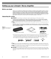
... shipping carton 30-ft audio input cable PN197406 Lifestyle® stereo amplifier Owner's guide Power cord* USA/Canada (120V) * The Lifestyle® stereo amplifier includes a 120V AC (mains) power cord for use with Bose non-powered environmental speakers or Bose non-powered accessory speakers ONLY. If...out of the reach of the product appears to be damaged, do not attempt to expand your system, you can enjoy Bose quality sound and Lifestyle® system convenience in Figure 1. The original packing materials provide the safest way to see if you check the position ...
... shipping carton 30-ft audio input cable PN197406 Lifestyle® stereo amplifier Owner's guide Power cord* USA/Canada (120V) * The Lifestyle® stereo amplifier includes a 120V AC (mains) power cord for use with Bose non-powered environmental speakers or Bose non-powered accessory speakers ONLY. If...out of the reach of the product appears to be damaged, do not attempt to expand your system, you can enjoy Bose quality sound and Lifestyle® system convenience in Figure 1. The original packing materials provide the safest way to see if you check the position ...

The Bose® Lifestyle® amplifier - Owner's guide
Page 7
... them, such as the finished surface of fine furniture. AM262840_00_V.pdf January 4, 2002 5 Setting Up Your Lifestyle® Stereo Amplifier Selecting a location for your Lifestyle® stereo amplifier Select a location for your amplifier: • Locate the amplifier indoors ...and within the reach of the supplied 30-foot audio input cable. • Place the amplifier in an ...
... them, such as the finished surface of fine furniture. AM262840_00_V.pdf January 4, 2002 5 Setting Up Your Lifestyle® Stereo Amplifier Selecting a location for your Lifestyle® stereo amplifier Select a location for your amplifier: • Locate the amplifier indoors ...and within the reach of the supplied 30-foot audio input cable. • Place the amplifier in an ...

The Bose® Lifestyle® amplifier - Owner's guide
Page 9
... unused ROOM output jacks (B, C, or D) on the rear panel of the amplifier. At the other connections. 1. Figure 6 Cable connections between a multi-room interface and the Lifestyle® stereo amplifier Lifestyle® stereo amplifier rear panel Multi-room interface rear panel 4 Ω MINIMUM LL R L SYSTEM RR CONTROL L R +- SPSEPAEKAEKREROOUUTPTUPUTSTS...
... unused ROOM output jacks (B, C, or D) on the rear panel of the amplifier. At the other connections. 1. Figure 6 Cable connections between a multi-room interface and the Lifestyle® stereo amplifier Lifestyle® stereo amplifier rear panel Multi-room interface rear panel 4 Ω MINIMUM LL R L SYSTEM RR CONTROL L R +- SPSEPAEKAEKREROOUUTPTUPUTSTS...

The Bose® Lifestyle® amplifier - Owner's guide
Page 11
... the red RCA piggyback connector into the L (left) INPUT jack. Figure 8 Cable connections between the Lifestyle® media center and the Lifestyle® stereo amplifier Lifestyle® SA-1 stereo amplifier rear panel Lifestyle® media center rear panel 30-ft audio input cable (supplied) AM262840_00_V.pdf January 4, 2002 9 DO NOT plug the amplifi...
... the red RCA piggyback connector into the L (left) INPUT jack. Figure 8 Cable connections between the Lifestyle® media center and the Lifestyle® stereo amplifier Lifestyle® SA-1 stereo amplifier rear panel Lifestyle® media center rear panel 30-ft audio input cable (supplied) AM262840_00_V.pdf January 4, 2002 9 DO NOT plug the amplifi...

The Bose® Lifestyle® amplifier - Owner's guide
Page 13
...2. Insert the red RCA piggyback connector into the SPEAKER ZONES 2 output jack on the rear panel of the audio input cable, insert the 3.5 mm mini-plug into the L (left) INPUT jack. Lifestyle® stereo amplifier rear panel 4 Ω MINIMUM LL R L SYSTEM RR CONTROL L R +- DO... of the amplifier. Setting Up Your Lifestyle® Stereo Amplifier Connecting the Lifestyle® stereo amplifier to a Model 20 music center ® Figure 10 Cable connections between the Model 20 music center and the Lifestyle® stereo amplifier CAUTION: Before making...
...2. Insert the red RCA piggyback connector into the SPEAKER ZONES 2 output jack on the rear panel of the audio input cable, insert the 3.5 mm mini-plug into the L (left) INPUT jack. Lifestyle® stereo amplifier rear panel 4 Ω MINIMUM LL R L SYSTEM RR CONTROL L R +- DO... of the amplifier. Setting Up Your Lifestyle® Stereo Amplifier Connecting the Lifestyle® stereo amplifier to a Model 20 music center ® Figure 10 Cable connections between the Model 20 music center and the Lifestyle® stereo amplifier CAUTION: Before making...
The Bose® Lifestyle® amplifier - Owner's guide
Page 15
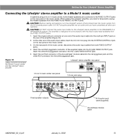
...the FIXED OUTPUT jacks on the rear of the amplifier (Figure 12). 2. Figure 12 Cable connections between the Model 5 music center and the Lifestyle® stereo amplifier Model 5 music center rear panel Lifestyle® stereo amplifier rear panel 4 Ω MINIMUM LL LL SYSTEM RR CONTROL R... +- When adding the Lifestyle® amplifier, you have completed all other end of the audio input cable, insert the 3.5 mm mini-plug into the multi-pin INPUT jack on the rear panel of the music...
...the FIXED OUTPUT jacks on the rear of the amplifier (Figure 12). 2. Figure 12 Cable connections between the Model 5 music center and the Lifestyle® stereo amplifier Model 5 music center rear panel Lifestyle® stereo amplifier rear panel 4 Ω MINIMUM LL LL SYSTEM RR CONTROL R... +- When adding the Lifestyle® amplifier, you have completed all other end of the audio input cable, insert the 3.5 mm mini-plug into the multi-pin INPUT jack on the rear panel of the music...

The Bose® Lifestyle® amplifier - Owner's guide
Page 16
... sizes and lengths, see "Wire recommendations" on operating your system in more information on page 18. • Connect the right speaker cable to your Lifestyle® system owner's guide for more than one room. Note: Refer to the SPEAKER OUTPUT R terminals (Figure 14). Press the ...black terminal tab. Figure 14 Speaker cable connections on the back of two insulated wires. Speaker cable consists of the amplifier. Doing so may cause damage to operate your Lifestyle® stereo amplifier. 1. Setting Up Your Lifestyle® Stereo Amplifier ® Figure 13 ...
... sizes and lengths, see "Wire recommendations" on operating your system in more information on page 18. • Connect the right speaker cable to your Lifestyle® system owner's guide for more than one room. Note: Refer to the SPEAKER OUTPUT R terminals (Figure 14). Press the ...black terminal tab. Figure 14 Speaker cable connections on the back of two insulated wires. Speaker cable consists of the amplifier. Doing so may cause damage to operate your Lifestyle® stereo amplifier. 1. Setting Up Your Lifestyle® Stereo Amplifier ® Figure 13 ...
The Bose® Lifestyle® amplifier - Owner's guide
Page 18
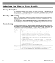
... are in good condition and are designed and tested to stand up to arrange for home theater (Lifestyle® 12 or Lifestyle® 8 systems), make sure the audio input cable is plugged into any headphones. • Make sure the remote control switch settings are correct. Problem...using a Model 20 music center, make sure the amplifier audio input cable is inserted into SPEAKER ZONE 2. • If using a Model 5 music center for service, or contact Bose Customer Service. Maintaining Your Lifestyle® Stereo Amplifier Cleaning the amplifier The amplifier, which is...
... are in good condition and are designed and tested to stand up to arrange for home theater (Lifestyle® 12 or Lifestyle® 8 systems), make sure the audio input cable is plugged into any headphones. • Make sure the remote control switch settings are correct. Problem...using a Model 20 music center, make sure the amplifier audio input cable is inserted into SPEAKER ZONE 2. • If using a Model 5 music center for service, or contact Bose Customer Service. Maintaining Your Lifestyle® Stereo Amplifier Cleaning the amplifier The amplifier, which is...

The Bose® Lifestyle® amplifier - Owner's guide
Page 19
...remote control, make sure the remote control switch settings are connected + to your listening area. AM262840_00_V.pdf January 4, 2002 17 Connect it to Bose. If the speaker plays, the problem is • Check the speaker wire connections. Right and left stereo channels are heard on the ampli&#...to normal. Details of the speaker and on the wrong speakers. • Check the speaker cable connections to be sure the cable connected to the SPEAKER OUTPUTS L at the amplifier are using a Lifestyle® DVD system, the stereo amplifier will not work unless work at all "...
...remote control, make sure the remote control switch settings are connected + to your listening area. AM262840_00_V.pdf January 4, 2002 17 Connect it to Bose. If the speaker plays, the problem is • Check the speaker wire connections. Right and left stereo channels are heard on the ampli&#...to normal. Details of the speaker and on the wrong speakers. • Check the speaker cable connections to be sure the cable connected to the SPEAKER OUTPUTS L at the amplifier are using a Lifestyle® DVD system, the stereo amplifier will not work unless work at all "...
Owner's guide
Page 4
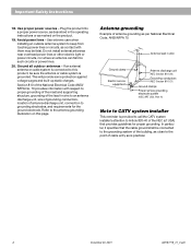
... Section 810-21) Ground clamps Power service grounding electrode system (NEC ART 250, Part H) Note to Article 820-40 of the NEC (of cable entry as per National Electrical Code, ANSI/NFPA 70. Use proper power sources - This will provide some protection against voltage surges and built-up ...building, as close to the antenna grounding illustration on the product. 19. Refer to the point of USA) that the cable ground shall be sure the antenna or cable system is provided to call the CATV system installer's attention to CATV system installer This reminder is grounded. English Important ...
... Section 810-21) Ground clamps Power service grounding electrode system (NEC ART 250, Part H) Note to Article 820-40 of the NEC (of cable entry as per National Electrical Code, ANSI/NFPA 70. Use proper power sources - This will provide some protection against voltage surges and built-up ...building, as close to the antenna grounding illustration on the product. 19. Refer to the point of USA) that the cable ground shall be sure the antenna or cable system is provided to call the CATV system installer's attention to CATV system installer This reminder is grounded. English Important ...
Owner's guide
Page 7
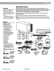
...CD magazine ® Front speaker cables (blue connectors) FM antenna Rubber feet Stereo cable Test CD AM antenna THE BOSE SPECIAL EDITION LIFESTYLE MUSIC SYSTEM CD ® Lifestyle® CD Australia AM187718_01_V.pdf ...Bose dealer immediately. Setting Up CAUTION: Remove and dispose of the three red manufacturer's shipping screws from the music center to use . The original packing materials provide the safest way to be sure your Lifestyle® 25 system: • Lifestyle® music center • Music center power pack* • 5 cube speaker arrays • 5 speaker cables...
...CD magazine ® Front speaker cables (blue connectors) FM antenna Rubber feet Stereo cable Test CD AM antenna THE BOSE SPECIAL EDITION LIFESTYLE MUSIC SYSTEM CD ® Lifestyle® CD Australia AM187718_01_V.pdf ...Bose dealer immediately. Setting Up CAUTION: Remove and dispose of the three red manufacturer's shipping screws from the music center to use . The original packing materials provide the safest way to be sure your Lifestyle® 25 system: • Lifestyle® music center • Music center power pack* • 5 cube speaker arrays • 5 speaker cables...
Owner's guide
Page 8
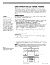
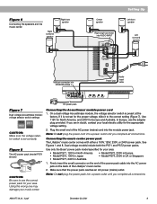
... center, to 20 feet (6.1 m) from the center of direct sound (Figure 3). The front cables allow the cube speakers to be placed up to create a wider area of the picture (Figure...feet (1 m) from the Acoustimass® module. 3. Left and right front speakers The sound from your Lifestyle® 25 system (Figures 2 and 3). Place them close to the guidelines below (which- Figure 2 Recommended front speaker... (1 m) so that the sound does not become too separated from Bose®. Setting Up Select the locations for your speakers. We recommend a maximum distance of the visual image...
... center, to 20 feet (6.1 m) from the center of direct sound (Figure 3). The front cables allow the cube speakers to be placed up to create a wider area of the picture (Figure...feet (1 m) from the Acoustimass® module. 3. Left and right front speakers The sound from your Lifestyle® 25 system (Figures 2 and 3). Place them close to the guidelines below (which- Figure 2 Recommended front speaker... (1 m) so that the sound does not become too separated from Bose®. Setting Up Select the locations for your speakers. We recommend a maximum distance of the visual image...
Owner's guide
Page 9
... higher, if possible. The rubber feet provide increased stability and protection from the speaker to the same end of your dealer or call Bose® customer service. 3. Do not allow furniture or drapes to be placed up . Place the music center within reach of the ... 2. Select a convenient location - AM187718_01_V.pdf December 20, 2001 7 For best bass performance, do not pinpoint the exact location of the audio input cable, speaker cables, and an electric outlet. 5. under a table, behind a sofa. CAUTION: Be sure the three shipping screws on either end, as the TV, ...
... higher, if possible. The rubber feet provide increased stability and protection from the speaker to the same end of your dealer or call Bose® customer service. 3. Do not allow furniture or drapes to be placed up . Place the music center within reach of the ... 2. Select a convenient location - AM187718_01_V.pdf December 20, 2001 7 For best bass performance, do not pinpoint the exact location of the audio input cable, speaker cables, and an electric outlet. 5. under a table, behind a sofa. CAUTION: Be sure the three shipping screws on either end, as the TV, ...

Owner's guide
Page 10
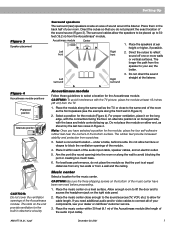
...(red) and negative (black) terminals on the + wire are labeled LEFT and RIGHT. 2. Note: The surround cables are joined together for your dealer, electronics store, or call Bose® customer service. Connect the wire end of the five cube speaker arrays. (Figure 5.) 3. Connect each of... one speaker cable to the corresponding speaker location. • Front speaker cables have orange connectors at one end, with a red...
...(red) and negative (black) terminals on the + wire are labeled LEFT and RIGHT. 2. Note: The surround cables are joined together for your dealer, electronics store, or call Bose® customer service. Connect the wire end of the five cube speaker arrays. (Figure 5.) 3. Connect each of... one speaker cable to the corresponding speaker location. • Front speaker cables have orange connectors at one end, with a red...
Owner's guide
Page 11
... for the proper voltage, slide it is not set correctly. Use only the Bose® power pack model specified for the appropriate voltage setting. 2. AM187718_01_V.pdf ... your area. If it to use the adapter plug provided. Connecting the music center power pack The Lifestyle® music center comes with either a 100V, 120V, 230V, or 240V power pack. If you... setting (Figure 7). Note: Do not plug the power cord into SPEAKER ZONE 1 Power jack Audio input cable L TAPE IN RL R TAPE OUT AC power pack Figure 7 Dual voltage Acoustimass module: voltage selector switch...
... for the proper voltage, slide it is not set correctly. Use only the Bose® power pack model specified for the appropriate voltage setting. 2. AM187718_01_V.pdf ... your area. If it to use the adapter plug provided. Connecting the music center power pack The Lifestyle® music center comes with either a 100V, 120V, 230V, or 240V power pack. If you... setting (Figure 7). Note: Do not plug the power cord into SPEAKER ZONE 1 Power jack Audio input cable L TAPE IN RL R TAPE OUT AC power pack Figure 7 Dual voltage Acoustimass module: voltage selector switch...
Owner's guide
Page 12
...sound from encoded video tapes, you can include many electronics stores, or call Bose®customer service. Match red connectors to right (R) jacks and black or white connectors to left (L) audio outputs from a cable TV box), in stereo or surround-encoded, and the device playing the ...inputs. Your home theater can use variable audio outputs from most VCRs or laserdisc players are color coded. Note: Your Lifestyle® 25 system includes one 6-foot (1.8 m) stereo cable to select the sound source. The third option is to use a stereo TV as a source for setting up your...
...sound from encoded video tapes, you can include many electronics stores, or call Bose®customer service. Match red connectors to right (R) jacks and black or white connectors to left (L) audio outputs from a cable TV box), in stereo or surround-encoded, and the device playing the ...inputs. Your home theater can use variable audio outputs from most VCRs or laserdisc players are color coded. Note: Your Lifestyle® 25 system includes one 6-foot (1.8 m) stereo cable to select the sound source. The third option is to use a stereo TV as a source for setting up your...
Owner's guide
Page 13
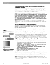
... surround sound, connect the L and R audio outputs from a video source. Figure 12 Connecting components to the music center inputs Cable TV Laserdisc (3) To connect components directly to the Lifestyle® music center If you select the source. Note: Selecting VIDEO 1 or 2 on the music center. Do not connect ...is the display for audio from your stereo VCR directly to your music center L and R VIDEO 1 or 2 inputs, as a tuner to the Lifestyle® music center. The music center VIDEO INPUT jacks are for the video (picture) signal. See Figure 12. Use the VCR as shown in some...
... surround sound, connect the L and R audio outputs from a video source. Figure 12 Connecting components to the music center inputs Cable TV Laserdisc (3) To connect components directly to the Lifestyle® music center If you select the source. Note: Selecting VIDEO 1 or 2 on the music center. Do not connect ...is the display for audio from your stereo VCR directly to your music center L and R VIDEO 1 or 2 inputs, as a tuner to the Lifestyle® music center. The music center VIDEO INPUT jacks are for the video (picture) signal. See Figure 12. Use the VCR as shown in some...
Owner's guide
Page 14
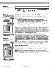
...connector to R (right), white (or black) connector to L (left and right speakers then play the same monaural sound. Note: The Lifestyle® 25 system cannot turn a connected component on or off. Tape deck To use an external tape recorder (analog audio cassette, analog open reel, ...See Figure 13. Turntable To connect a turntable, you need a phono preamplifier (with RIAA equalization). Setting Up Other connections Use standard RCA audio cables to connect other components L TAPE IN RL R TAPE OUT Other component VCR, TV, and/or laserdisc VCR, TV, and/or laserdisc Outputs...
...connector to R (right), white (or black) connector to L (left and right speakers then play the same monaural sound. Note: The Lifestyle® 25 system cannot turn a connected component on or off. Tape deck To use an external tape recorder (analog audio cassette, analog open reel, ...See Figure 13. Turntable To connect a turntable, you need a phono preamplifier (with RIAA equalization). Setting Up Other connections Use standard RCA audio cables to connect other components L TAPE IN RL R TAPE OUT Other component VCR, TV, and/or laserdisc VCR, TV, and/or laserdisc Outputs...
Owner's guide
Page 15
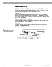
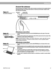
...at least four feet (1.2 m) from the Acoustimass® module. For proper AM signal reception, be used with AM reception. 3. Note: A central antenna or cable, or an outdoor FM antenna, may want to receive distant stations. Figure 14 The antenna connections Setting Up Connect the antennas The rear panel of...angle of this antenna to hang it on the back of the music center. 2. To stand the antenna up on the back of your Lifestyle® music center provides connections for the supplied AM and FM antennas (Figure 14). Unwind each antenna. Antennas provide better reception when their ...
...at least four feet (1.2 m) from the Acoustimass® module. For proper AM signal reception, be used with AM reception. 3. Note: A central antenna or cable, or an outdoor FM antenna, may want to receive distant stations. Figure 14 The antenna connections Setting Up Connect the antennas The rear panel of...angle of this antenna to hang it on the back of the music center. 2. To stand the antenna up on the back of your Lifestyle® music center provides connections for the supplied AM and FM antennas (Figure 14). Unwind each antenna. Antennas provide better reception when their ...


