
User Manual in English
Page 1
... you for car audio entertainment! USER'S MANUAL page CONTENTS 2 Introduction 2 What is included? 3 Features 3 About 2 Ohm operation 4 General precautions 4 Installation precautions 4 Mounting the amplifier 5 Connecting the amplifier 6 Low level input wiring 9 High level input wiring 10 2CH Power and Speaker wiring 2CH and Bridged Modes 11 2CH Power and Speaker wiring TriMode 12 4CH Power and Speaker wiring 4CH and Bridged Modes 13 4CH Power and Speaker wiring TriMode 14 MonoBlock Power and Speaker wiring 15 Troubleshooting 16 Specifications PHANTOM MOSFET Amplifier User's Manual - page...
... you for car audio entertainment! USER'S MANUAL page CONTENTS 2 Introduction 2 What is included? 3 Features 3 About 2 Ohm operation 4 General precautions 4 Installation precautions 4 Mounting the amplifier 5 Connecting the amplifier 6 Low level input wiring 9 High level input wiring 10 2CH Power and Speaker wiring 2CH and Bridged Modes 11 2CH Power and Speaker wiring TriMode 12 4CH Power and Speaker wiring 4CH and Bridged Modes 13 4CH Power and Speaker wiring TriMode 14 MonoBlock Power and Speaker wiring 15 Troubleshooting 16 Specifications PHANTOM MOSFET Amplifier User's Manual - page...
User Manual in English
Page 2
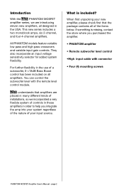
All PHANTOM models feature variable low pass and high pass crossovers and variable input gain controls. understands that the package contains all amplifiers. For further flexibility in the use of a subwoofer, 0-+18dB Bass Boost control has been included on all of the items below. You can control the subwoofer level with connector • Four (4) mounting screws PHANTOM MOSFET Amplifier User's Manual - This new series includes a two monoblock amps, six 2-channel, and four 4-channel amplifiers. What...
All PHANTOM models feature variable low pass and high pass crossovers and variable input gain controls. understands that the package contains all amplifiers. For further flexibility in the use of a subwoofer, 0-+18dB Bass Boost control has been included on all of the items below. You can control the subwoofer level with connector • Four (4) mounting screws PHANTOM MOSFET Amplifier User's Manual - This new series includes a two monoblock amps, six 2-channel, and four 4-channel amplifiers. What...
User Manual in English
Page 3
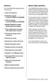
... Width Modulated) Power Supply • 2 Ohm stable stereo operation with output power increase • Thermal and speaker short protection • Soft turn-on circuit • Remote turn-on/turn-off circuit • Variable input gain control • Variable low pass crossover(s) • Fixed high pass crossover(s) • Variable 0 to +18dB Bass Boost • Gold-plated RCA low level and high level inputs • LED power and protection indicators • Black anodized heatsink • Remote subwoofer level control About 2 Ohm operation Your PHANTOM amplifier has been designed...
... Width Modulated) Power Supply • 2 Ohm stable stereo operation with output power increase • Thermal and speaker short protection • Soft turn-on circuit • Remote turn-on/turn-off circuit • Variable input gain control • Variable low pass crossover(s) • Fixed high pass crossover(s) • Variable 0 to +18dB Bass Boost • Gold-plated RCA low level and high level inputs • LED power and protection indicators • Black anodized heatsink • Remote subwoofer level control About 2 Ohm operation Your PHANTOM amplifier has been designed...
User Manual in English
Page 4
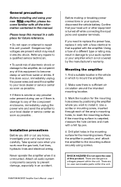
... the mounting hole screws by the manufacturer's warranty. There are no user-serviceable parts within the unit. Take special care when you need to replace the power fuse, replace it only with a fuse identical to the mounting surface securely using your system, disconnect the vehicle battery. Attach all the infor- If you work near the gas tank, fuel lines, hydraulic lines and electrical wiring. Make sure there is...
... the mounting hole screws by the manufacturer's warranty. There are no user-serviceable parts within the unit. Take special care when you need to replace the power fuse, replace it only with a fuse identical to the mounting surface securely using your system, disconnect the vehicle battery. Attach all the infor- If you work near the gas tank, fuel lines, hydraulic lines and electrical wiring. Make sure there is...
User Manual in English
Page 5
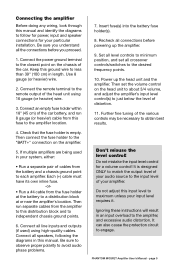
... ground point to each amplifier. Connect all the connections before powering up the head unit and the amplifier. Recheck all connections before you understand all line inputs and outputs (if used in length. Further fine tuning of the car battery, and run separate cables from this fuse to the amplifier location. 4. PHANTOM MOSFET Amplifier User's Manual - Connecting the amplifier Before doing any wiring, look through this manual and identify the diagrams to follow for power, input and speaker connections for a volume control! Connect the power ground terminal...
... ground point to each amplifier. Connect all the connections before powering up the head unit and the amplifier. Recheck all connections before you understand all line inputs and outputs (if used in length. Further fine tuning of the car battery, and run separate cables from this fuse to the amplifier location. 4. PHANTOM MOSFET Amplifier User's Manual - Connecting the amplifier Before doing any wiring, look through this manual and identify the diagrams to follow for power, input and speaker connections for a volume control! Connect the power ground terminal...
User Manual in English
Page 6
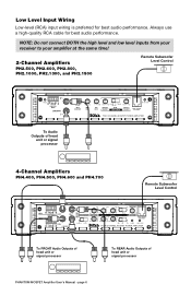
... connect BOTH the high level and low level inputs from your receiver to your amplifier at the same time! 2-Channel Amplifiers PH2.500, PH2.600, PH2.800, PH2.1000, PH2.1300, and PH2.1500 Remote Subwoofer Level Control R POWER RL HIGH LEVEL INPUTS LOW INPUTS L 100mV-2V 2V-8V INPUT SENSITIVITY min max INPUT LEVEL 0 +18dB BASS BOOST 50Hz 500Hz HIGH FULL LOW HIGH PASS MODE FREQUENCY CROSSOVER 45Hz 90Hz LOW PASS FREQUENCY PROTECTION REMOTE SUBWOOFER LEVEL CONTROL TWO C HANNE L M OSF ET POWE R AMPL IFIER To Audio Outputs of head unit or signal processor 4-Channel Amplifiers...
... connect BOTH the high level and low level inputs from your receiver to your amplifier at the same time! 2-Channel Amplifiers PH2.500, PH2.600, PH2.800, PH2.1000, PH2.1300, and PH2.1500 Remote Subwoofer Level Control R POWER RL HIGH LEVEL INPUTS LOW INPUTS L 100mV-2V 2V-8V INPUT SENSITIVITY min max INPUT LEVEL 0 +18dB BASS BOOST 50Hz 500Hz HIGH FULL LOW HIGH PASS MODE FREQUENCY CROSSOVER 45Hz 90Hz LOW PASS FREQUENCY PROTECTION REMOTE SUBWOOFER LEVEL CONTROL TWO C HANNE L M OSF ET POWE R AMPL IFIER To Audio Outputs of head unit or signal processor 4-Channel Amplifiers...
User Manual in English
Page 7
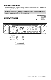
... PH2500M Remote Subwoofer Level Control R POWER R L HIGH LEVEL INPUTS LOW INPUTS L 2V-8V 100mV-2V min max INPUT SENSITIVITY INPUT LEVEL 0 +18dB BASS BOOST LOW FULL MODE CROSSOVER 45Hz 90Hz LOW PASS FREQUENCY PROTECTION REMOTE SUBWOOFER LEVEL CONTROL M OSF E T M ONOBL OCK POWE R AM PL I FI E R To Audio Outputs of head unit or signal processor PHANTOM MOSFET Amplifier User's Manual - Low Level Input Wiring Low-level (RCA) input wiring is preferred for best audio performance. NOTE: Do not connect BOTH the high level and low level inputs from your receiver to your amplifier at...
... PH2500M Remote Subwoofer Level Control R POWER R L HIGH LEVEL INPUTS LOW INPUTS L 2V-8V 100mV-2V min max INPUT SENSITIVITY INPUT LEVEL 0 +18dB BASS BOOST LOW FULL MODE CROSSOVER 45Hz 90Hz LOW PASS FREQUENCY PROTECTION REMOTE SUBWOOFER LEVEL CONTROL M OSF E T M ONOBL OCK POWE R AM PL I FI E R To Audio Outputs of head unit or signal processor PHANTOM MOSFET Amplifier User's Manual - Low Level Input Wiring Low-level (RCA) input wiring is preferred for best audio performance. NOTE: Do not connect BOTH the high level and low level inputs from your receiver to your amplifier at...
User Manual in English
Page 8
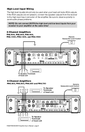
... problems. NOTE: Do not connect BOTH the high level and low level inputs from the receiver to your head unit lacks RCA outputs. High Level Input Wiring The high level input(s) should only be used when your amplifier at the same time! 2-Channel Amplifiers PH2.500, PH2.600, PH2.800, PH2.1000, PH2.1300, and PH2.1500 Remote Subwoofer Level Control R POWER R L HIGH LEVEL INPUTS LOW INPUTS L 100mV-2V 2V-8V INPUT SENSITIVITY min max INPUT LEVEL 0 +18dB 50Hz 500Hz HIGH FULL LOW BASS BOOST HIGH PASS MODE FREQUENCY CROSSOVER 45Hz 90Hz LOW PASS FREQUENCY PROTECTION REMOTE...
... problems. NOTE: Do not connect BOTH the high level and low level inputs from the receiver to your head unit lacks RCA outputs. High Level Input Wiring The high level input(s) should only be used when your amplifier at the same time! 2-Channel Amplifiers PH2.500, PH2.600, PH2.800, PH2.1000, PH2.1300, and PH2.1500 Remote Subwoofer Level Control R POWER R L HIGH LEVEL INPUTS LOW INPUTS L 100mV-2V 2V-8V INPUT SENSITIVITY min max INPUT LEVEL 0 +18dB 50Hz 500Hz HIGH FULL LOW BASS BOOST HIGH PASS MODE FREQUENCY CROSSOVER 45Hz 90Hz LOW PASS FREQUENCY PROTECTION REMOTE...

User Manual in English
Page 9
... to avoid audio phase problems. NOTE: Do not connect BOTH the high level and low level inputs from the receiver to your head unit lacks RCA outputs. L+ To Speaker Terminals of the amplifier. page 9 L- High Level Input Wiring The high level input(s) should only be used when your amplifier at the same time! MonoBlock Amplifier PH1500M and PH2500M R POWER R L HIGH LEVEL INPUTS LOW INPUTS L 2V-8V 100mV-2V min max INPUT SENSITIVITY INPUT LEVEL 0 +18dB BASS BOOST LOW FULL MODE CROSSOVER 45Hz 90Hz LOW PASS FREQUENCY PROTECTION REMOTE SUBWOOFER LEVEL CONTROL M OSF...
... to avoid audio phase problems. NOTE: Do not connect BOTH the high level and low level inputs from the receiver to your head unit lacks RCA outputs. L+ To Speaker Terminals of the amplifier. page 9 L- High Level Input Wiring The high level input(s) should only be used when your amplifier at the same time! MonoBlock Amplifier PH1500M and PH2500M R POWER R L HIGH LEVEL INPUTS LOW INPUTS L 2V-8V 100mV-2V min max INPUT SENSITIVITY INPUT LEVEL 0 +18dB BASS BOOST LOW FULL MODE CROSSOVER 45Hz 90Hz LOW PASS FREQUENCY PROTECTION REMOTE SUBWOOFER LEVEL CONTROL M OSF...
User Manual in English
Page 10
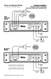
...GND REMOTE POWER CONNECTIONS Chassis ground point to REMOTE TURN-ON terminal of the subwoofer to the R (-) amplifier terminal. Connect the Negative (-) terminal of head unit FUSE Battery + - Speaker + - PHANTOM MOSFET Amplifier User's Manual - Power and Speaker Wiring 2 Channel and Bridged Modes 2-Channel Amplifiers PH2.500, PH2.600, PH2.800, PH2.1000, PH2.1300, and PH2.1500 Two Channel Mode + LEFT - RIGHT Speaker SPEAKER IMPEDANCE 2-8 OHMS L R SPEAKER CONNECTIONS BRIDGED MODE Bridged Mode FUSES +12V GND REMOTE POWER CONNECTIONS Chassis ground point to REMOTE TURN...
...GND REMOTE POWER CONNECTIONS Chassis ground point to REMOTE TURN-ON terminal of the subwoofer to the R (-) amplifier terminal. Connect the Negative (-) terminal of head unit FUSE Battery + - Speaker + - PHANTOM MOSFET Amplifier User's Manual - Power and Speaker Wiring 2 Channel and Bridged Modes 2-Channel Amplifiers PH2.500, PH2.600, PH2.800, PH2.1000, PH2.1300, and PH2.1500 Two Channel Mode + LEFT - RIGHT Speaker SPEAKER IMPEDANCE 2-8 OHMS L R SPEAKER CONNECTIONS BRIDGED MODE Bridged Mode FUSES +12V GND REMOTE POWER CONNECTIONS Chassis ground point to REMOTE TURN...
User Manual in English
Page 11
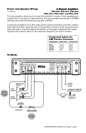
... speakers plus a subwoofer on one pair of output channels. The main speakers will operate in STEREO while the subwoofer simultaneously operates in MONO. Insert high pass filter capacitors and a low pass filter inductor into the wiring as shown below. Tri-Mode Component values for the crossover frequency you to connect this amplifier to REMOTE TURN-ON terminal of head unit FUSE Battery PHANTOM MOSFET Amplifier User's Manual - Power and Speaker Wiring 2-Channel Amplifiers Tri-Mode PH2.500, PH2.600, PH2.800, PH2.1000, PH2.1300, and PH2.1500 Tri-mode...
... speakers plus a subwoofer on one pair of output channels. The main speakers will operate in STEREO while the subwoofer simultaneously operates in MONO. Insert high pass filter capacitors and a low pass filter inductor into the wiring as shown below. Tri-Mode Component values for the crossover frequency you to connect this amplifier to REMOTE TURN-ON terminal of head unit FUSE Battery PHANTOM MOSFET Amplifier User's Manual - Power and Speaker Wiring 2-Channel Amplifiers Tri-Mode PH2.500, PH2.600, PH2.800, PH2.1000, PH2.1300, and PH2.1500 Tri-mode...
User Manual in English
Page 12
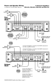
... Amplifier User's Manual - Connect the Positive (+) terminal of the RIGHT subwoofer to the CH2 (-) amplifier terminal. Power and Speaker Wiring 4-Channel Amplifiers 4 Channel and Bridged Modes PH4.400, PH4.500, PH4.600 and PH4.700 CH2 Speaker CH1 Speaker Four Channel Mode SPEAKER IMPEDANCE 2-8 OHMS CH1 CH2 SPEAKER CONNECTIONS BRIDGED MODE CH3 CH4 SPEAKER CONNECTIONS BRIDGED MODE +12V GND FUSES REMOTE POWER CONNECTIONS SPEAKER IMPEDANCE 2-8 OHMS CH3 Speaker CH4 Speaker SPEAKER IMPEDANCE 4-8 OHMS RIGHT Subwoofer Chassis ground point to REMOTE TURN-ON terminal of head unit...
... Amplifier User's Manual - Connect the Positive (+) terminal of the RIGHT subwoofer to the CH2 (-) amplifier terminal. Power and Speaker Wiring 4-Channel Amplifiers 4 Channel and Bridged Modes PH4.400, PH4.500, PH4.600 and PH4.700 CH2 Speaker CH1 Speaker Four Channel Mode SPEAKER IMPEDANCE 2-8 OHMS CH1 CH2 SPEAKER CONNECTIONS BRIDGED MODE CH3 CH4 SPEAKER CONNECTIONS BRIDGED MODE +12V GND FUSES REMOTE POWER CONNECTIONS SPEAKER IMPEDANCE 2-8 OHMS CH3 Speaker CH4 Speaker SPEAKER IMPEDANCE 4-8 OHMS RIGHT Subwoofer Chassis ground point to REMOTE TURN-ON terminal of head unit...
User Manual in English
Page 13
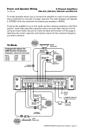
... filter inductor LEFT Subwoofer Chassis ground point to a pair of main speakers plus a subwoofer on one pair of head unit FUSE Battery PHANTOM MOSFET Amplifier User's Manual - Insert high pass filter capacitors and a low pass filter inductor into the wiring as shown below. The main speakers will operate in STEREO while the subwoofer simultaneously operates in the FULL position. To set up the amplifier to run in this amplifier to REMOTE TURN-ON terminal of output channels...
... filter inductor LEFT Subwoofer Chassis ground point to a pair of main speakers plus a subwoofer on one pair of head unit FUSE Battery PHANTOM MOSFET Amplifier User's Manual - Insert high pass filter capacitors and a low pass filter inductor into the wiring as shown below. The main speakers will operate in STEREO while the subwoofer simultaneously operates in the FULL position. To set up the amplifier to run in this amplifier to REMOTE TURN-ON terminal of output channels...
User Manual in English
Page 14
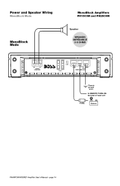
page 14 Power and Speaker Wiring MonoBlock Mode MonoBlock Amplifiers PH1500M and PH2500M MonoBlock Mode + Speaker - SPEAKER IMPEDANCE 2-8 OHMS SPEAKER CONNECTIONS FUSES +12V GND REMOTE POWER CONNECTIONS Chassis ground point to REMOTE TURN-ON terminal of head unit FUSE Battery PHANTOM MOSFET Amplifier User's Manual -
page 14 Power and Speaker Wiring MonoBlock Mode MonoBlock Amplifiers PH1500M and PH2500M MonoBlock Mode + Speaker - SPEAKER IMPEDANCE 2-8 OHMS SPEAKER CONNECTIONS FUSES +12V GND REMOTE POWER CONNECTIONS Chassis ground point to REMOTE TURN-ON terminal of head unit FUSE Battery PHANTOM MOSFET Amplifier User's Manual -
User Manual in English
Page 15
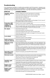
Troubleshooting If you have a good ground connection. Check that there is properly grounded. Check all speaker wiring. Check that the Remote Input (Turn-On) has at least 3VDC. Check that amplifier is battery power on speaker leads. Low output. Check all fuses, replace if necessary. Check for short circuits on the (+) terminal. Check that the Protection LED is set to match the signal level of the head unit. Always try to the vehicle chassis...
Troubleshooting If you have a good ground connection. Check that there is properly grounded. Check all speaker wiring. Check that the Remote Input (Turn-On) has at least 3VDC. Check that amplifier is battery power on speaker leads. Low output. Check all fuses, replace if necessary. Check for short circuits on the (+) terminal. Check that the Protection LED is set to match the signal level of the head unit. Always try to the vehicle chassis...


