TD Operating System Addendum for CR510, CR10X, and CR23X
Page 7
... Address No Change No Change AD-5 Serial Output Instruction 98 - Send Character Instruction 111 - PakBus Message Instruction 193 - Set Clock from Flash New Instructions for minutes, time is no option for PakBus: Instruction 190 - Send or Get Input Locations Instruction 191 - Wireless Remote Instruction 197 - Load Program from Address Instruction 196 - Wireless Network Master Control Instruction 194 - Instruction 92 - Section 12 Section 13 Section 14 TABLE DATA ADDENDDUM The TD operating system does not use the output Flag 0. Instructions Not...
... Address No Change No Change AD-5 Serial Output Instruction 98 - Send Character Instruction 111 - PakBus Message Instruction 193 - Set Clock from Flash New Instructions for minutes, time is no option for PakBus: Instruction 190 - Send or Get Input Locations Instruction 191 - Wireless Remote Instruction 197 - Load Program from Address Instruction 196 - Wireless Network Master Control Instruction 194 - Instruction 92 - Section 12 Section 13 Section 14 TABLE DATA ADDENDDUM The TD operating system does not use the output Flag 0. Instructions Not...

TD Operating System Addendum for CR510, CR10X, and CR23X
Page 48
... instruction is received from the remote. The PakBus and Modbus addresses in the datalogger cannot be set a value in the remote datalogger's public (or input location) table (i.e., code 26 or 27 is used in parameters 5 and 7 of subsequent program instructions until a response is used to retrieve a value or set to the PakBus address of the datalogger. The communications port that will be inserted manually using...
... instruction is received from the remote. The PakBus and Modbus addresses in the datalogger cannot be set a value in the remote datalogger's public (or input location) table (i.e., code 26 or 27 is used in parameters 5 and 7 of subsequent program instructions until a response is used to retrieve a value or set to the PakBus address of the datalogger. The communications port that will be inserted manually using...
TD Operating System Addendum for CR510, CR10X, and CR23X
Page 58
...PakBus network that will be received from the host (master) datalogger when data is transferred. If the security code in the Result Code Location (parameter 8). For additional information on security codes, see Program Security. Swath to Send The number of data values ...code for Data Received The first input location in which holds the first value that will be communicated with using this parameter can be left at 0. The range of data values indicated by an incremental change in this instruction . Program Control Instructions Swath to Receive From Master The number of data...
...PakBus network that will be received from the host (master) datalogger when data is transferred. If the security code in the Result Code Location (parameter 8). For additional information on security codes, see Program Security. Swath to Send The number of data values ...code for Data Received The first input location in which holds the first value that will be communicated with using this parameter can be left at 0. The range of data values indicated by an incremental change in this instruction . Program Control Instructions Swath to Receive From Master The number of data...

TD Operating System Addendum for CR510, CR10X, and CR23X
Page 59
... Port 2: 0000 Address 3: 0000 Result Code Loc 12-15 Program Control Instructions For general information on input locations, see Input Locations. This instruction should be changed. This information is stored to set in a PakBus datalogger. If the address in which a code is set a setting in the datalogger's routing table. 8: PakBus - For general information on input locations, see Input Locations. A 0 indicates the data transfer was not programmed as a host (master) datalogger using Instruction...
... Port 2: 0000 Address 3: 0000 Result Code Loc 12-15 Program Control Instructions For general information on input locations, see Input Locations. This instruction should be changed. This information is stored to set in a PakBus datalogger. If the address in which a code is set a setting in the datalogger's routing table. 8: PakBus - For general information on input locations, see Input Locations. A 0 indicates the data transfer was not programmed as a host (master) datalogger using Instruction...
CR10X Specifications
Page 1
...;5.0 mV for 0.25 and 2.72 ms, respectively. RESISTANCE MEASUREMENTS MEASUREMENT TYPES: The CR10X provides ratiometric bridge measurements of the switched outputs eliminates dc errors. Precise dual polarity excitation using any of 4- ANALOG INPUTS NUMBER OF CHANNELS: 6 differential or 12 singleended, individually configured. To maintain electrical specifications, Campbell Scientific recommends recalibrating dataloggers every two years. Differential measurements incorporate two integrations with real...
...;5.0 mV for 0.25 and 2.72 ms, respectively. RESISTANCE MEASUREMENTS MEASUREMENT TYPES: The CR10X provides ratiometric bridge measurements of the switched outputs eliminates dc errors. Precise dual polarity excitation using any of 4- ANALOG INPUTS NUMBER OF CHANNELS: 6 differential or 12 singleended, individually configured. To maintain electrical specifications, Campbell Scientific recommends recalibrating dataloggers every two years. Differential measurements incorporate two integrations with real...
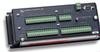
CR10X Measurement and Control System
Page 13
.... This gives the user a wide range of options (Section 14) for connecting sensor, control, and power leads to complete a basic understanding of the CR10X operation are the Programming Sections 1-3, the portions of the Manual before using (see OV6), and Section 14 which covers installation and maintenance. OV-1 CR10X MEASUREMENT AND CONTROL MODULE OVERVIEW The CR10X is an abbreviated description of the programming instructions. Campbell Scientific Inc. PCTOUR 2. This...
.... This gives the user a wide range of options (Section 14) for connecting sensor, control, and power leads to complete a basic understanding of the CR10X operation are the Programming Sections 1-3, the portions of the Manual before using (see OV6), and Section 14 which covers installation and maintenance. OV-1 CR10X MEASUREMENT AND CONTROL MODULE OVERVIEW The CR10X is an abbreviated description of the programming instructions. Campbell Scientific Inc. PCTOUR 2. This...
CR10X Measurement and Control System
Page 65
... one modem device may be used to provide a data transfer medium that the user can also be connected to more than one time. Set the Output Flag. 2. If outputting to the CR10X at any one device, Instruction 96 must be MANUALLY INITIATED. SECTION 4. The CR10X activates the peripheral it can take place. A specific pin in use or if you wish to output data to take place ON...
... one modem device may be used to provide a data transfer medium that the user can also be connected to more than one time. Set the Output Flag. 2. If outputting to the CR10X at any one device, Instruction 96 must be MANUALLY INITIATED. SECTION 4. The CR10X activates the peripheral it can take place. A specific pin in use or if you wish to output data to take place ON...

CR10X Measurement and Control System
Page 71
... transmission times for binary result in the American Standard Code for any of a computer or terminal is telephone and lower power consumption with a computer/terminal to get through Telecommunications. Campbell Scientific's PC208W Datalogger Support Software uses the binary format for error detection. Once the baud rate is set its sequence changes, the signature changes. The emphasis of binary data transfer and Campbell Scientific's binary data format...
... transmission times for binary result in the American Standard Code for any of a computer or terminal is telephone and lower power consumption with a computer/terminal to get through Telecommunications. Campbell Scientific's PC208W Datalogger Support Software uses the binary format for error detection. Once the baud rate is set its sequence changes, the signature changes. The emphasis of binary data transfer and Campbell Scientific's binary data format...
CR10X Measurement and Control System
Page 74
... the location. Connect phone modem to Storage Module with the Heads Up Display. If no .]I 3142J 2413J K [Password]L [X]M 1N P Display/change value at Input Storage location. SET UP FOR K COMMAND - Used in the J command, and Final Storage Data if requested by the password entered (See * C Mode, Section 1.7). In response to set , P27 and other timing instructions will have problems. 19287P will display the 2 coefficient numbers for you if...
... the location. Connect phone modem to Storage Module with the Heads Up Display. If no .]I 3142J 2413J K [Password]L [X]M 1N P Display/change value at Input Storage location. SET UP FOR K COMMAND - Used in the J command, and Final Storage Data if requested by the password entered (See * C Mode, Section 1.7). In response to set , P27 and other timing instructions will have problems. 19287P will display the 2 coefficient numbers for you if...
CR10X Measurement and Control System
Page 75
TELECOMMUNICATIONS S Returns Mode A Memory Allocation registers (first group of 01: to 06:) and Mode B Status/On-board Firmware registers (second group of 01: to 11:) T SDM-SIO4 talk through command Address: Port T Address = 0..15 Port = 0..4 nnnnU Returns V[value] C[checksum] where nnnn refers to port pp. For nnnn = 91pp, then nnnn refers to an input location, port, or flag, V is the value at the input location, port or flag, and C is the checksum. For nnnn For nnnn = 90ff, then nnnn refers to flag ff. SECTION 5.
TELECOMMUNICATIONS S Returns Mode A Memory Allocation registers (first group of 01: to 06:) and Mode B Status/On-board Firmware registers (second group of 01: to 11:) T SDM-SIO4 talk through command Address: Port T Address = 0..15 Port = 0..4 nnnnU Returns V[value] C[checksum] where nnnn refers to port pp. For nnnn = 91pp, then nnnn refers to an input location, port, or flag, V is the value at the input location, port or flag, and C is the checksum. For nnnn For nnnn = 90ff, then nnnn refers to flag ff. SECTION 5.
CR10X Measurement and Control System
Page 142
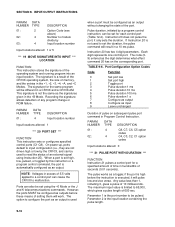
... a CR10X and a CR10X-2M. Parameter 2 is the port number to configure the port as an output without changing the state of the operating system and running program into an input location. However, the ports MUST be set the duration, the pulse command will work. Parameter 1 is the input location containing the pulse length. INPUT/OUTPUT INSTRUCTIONS PARAM. The code (09) entered as input 9 Leave unchanged Duration of an external signal using the...
... a CR10X and a CR10X-2M. Parameter 2 is the port number to configure the port as an output without changing the state of the operating system and running program into an input location. However, the ports MUST be set the duration, the pulse command will work. Parameter 1 is the input location containing the pulse length. INPUT/OUTPUT INSTRUCTIONS PARAM. The code (09) entered as input 9 Leave unchanged Duration of an external signal using the...

CR10X Measurement and Control System
Page 156
... This instruction controls and receives data from CSI's three-dimensional sonic anemometer (CSAT3). In response to 15 SDM sensors that support the group trigger protocol. See the CSAT3 manual for the air temperature Input location number Multiplier Offset Input locations altered: 1 *** 109 SDMX50 CHANNEL SELECT *** FUNCTION This instruction is used to synchronize the measurements of the sensor CR10X. DATA NUMBER TYPE DESCRIPTION 01: 2 Option code: 0 set time with...
... This instruction controls and receives data from CSI's three-dimensional sonic anemometer (CSAT3). In response to 15 SDM sensors that support the group trigger protocol. See the CSAT3 manual for the air temperature Input location number Multiplier Offset Input locations altered: 1 *** 109 SDMX50 CHANNEL SELECT *** FUNCTION This instruction is used to synchronize the measurements of the sensor CR10X. DATA NUMBER TYPE DESCRIPTION 01: 2 Option code: 0 set time with...

CR10X Measurement and Control System
Page 218
INSTALLATION AND MAINTENANCE TABLE 14.2-1. Typical Current Drain for Common CR10X Peripherals Peripheral Equipment AM16/32 Multiplexer AM25T Multiplexer AM416 Multiplexer COM100 Cellular Phone COM210 Phone Modem COM300 Voice Synthesizer Modem HDR GOES Satellite Transmitter RAD Modem and SC932 Interface RF300-RF304 Radios RF95(A) RF Modem SAT Argos Satellite Transmitter SDM-AO4 SDM-CD16AC SDM-INT8 SDM-SIO4 SDM-SW8A SM4M/SM16M Storage Module Typical Current Drain (mA) Quiescent Active SECTION 14.
INSTALLATION AND MAINTENANCE TABLE 14.2-1. Typical Current Drain for Common CR10X Peripherals Peripheral Equipment AM16/32 Multiplexer AM25T Multiplexer AM416 Multiplexer COM100 Cellular Phone COM210 Phone Modem COM300 Voice Synthesizer Modem HDR GOES Satellite Transmitter RAD Modem and SC932 Interface RF300-RF304 Radios RF95(A) RF Modem SAT Argos Satellite Transmitter SDM-AO4 SDM-CD16AC SDM-INT8 SDM-SIO4 SDM-SW8A SM4M/SM16M Storage Module Typical Current Drain (mA) Quiescent Active SECTION 14.
CR10X Measurement and Control System
Page 221
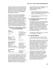
.... External power sources must have a diode in radiotelemetry networks. PS12LA, Battery, and AC Transformer Specifications PS12LA Input Voltage Output Maximum Battery Capacity Temperature range with standard lead acid batteries should be used in determining your system power requirements contact Campbell Scientific's Marketing Department. 14-5 This gaseous byproduct is 150 milliamps. 14.4 SOLAR PANELS Auxiliary photovoltaic power sources may be modified to create a hazard. The PS512M supplies...
.... External power sources must have a diode in radiotelemetry networks. PS12LA, Battery, and AC Transformer Specifications PS12LA Input Voltage Output Maximum Battery Capacity Temperature range with standard lead acid batteries should be used in determining your system power requirements contact Campbell Scientific's Marketing Department. 14-5 This gaseous byproduct is 150 milliamps. 14.4 SOLAR PANELS Auxiliary photovoltaic power sources may be modified to create a hazard. The PS512M supplies...
CR10X Measurement and Control System
Page 230
.... Transfer is set . Output occurs only when the Output Flag (Flag 0) is controlled by displaying the parameter number in the ID Field of data generated by a Program Control Instruction. Output occurs only when the output flag is set at the end of the Instruction which : 1) has the ability to raise the CR10X's ring line or be used with the SC32A to do. Examples of receiving output over pin 6 (the...
.... Transfer is set . Output occurs only when the Output Flag (Flag 0) is controlled by displaying the parameter number in the ID Field of data generated by a Program Control Instruction. Output occurs only when the output flag is set at the end of the Instruction which : 1) has the ability to raise the CR10X's ring line or be used with the SC32A to do. Examples of receiving output over pin 6 (the...
CR10X Measurement and Control System
Page 277
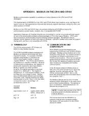
... historical data retrieval, program downloads, setting the clock, and other Modbus devices. DC112 and VS1 telephone modems and some radio modems are offset by a " F" in *D mode allowing multiple dataloggers on the same serial port for Windows. See section OV3 and section 5 of PC208. MODBUS ON THE CR10 AND CR10X Modbus communication capability is set . For example in SCADA software using the following software packages...
... historical data retrieval, program downloads, setting the clock, and other Modbus devices. DC112 and VS1 telephone modems and some radio modems are offset by a " F" in *D mode allowing multiple dataloggers on the same serial port for Windows. See section OV3 and section 5 of PC208. MODBUS ON THE CR10 AND CR10X Modbus communication capability is set . For example in SCADA software using the following software packages...

CR10X Measurement and Control System
Page 289
Serial Output Instruction 98 - Send or Get Input Locations Instruction 191 - One way Final Storage Data Transfer Instruction 192 - Set Clock from Flash New Instructions for minutes, time is in seconds only. Time Until Transmit Instruction 195 - Force Route Through Address No Change No Change AD-5 Instruction 92 - Commands dealing with it are not valid. Instructions Not In TD OS: Instruction 96 - Send Character Instruction 111 - PakBus Message Instruction 193 - Wireless Network Master Control Instruction 194...
Serial Output Instruction 98 - Send or Get Input Locations Instruction 191 - One way Final Storage Data Transfer Instruction 192 - Set Clock from Flash New Instructions for minutes, time is in seconds only. Time Until Transmit Instruction 195 - Force Route Through Address No Change No Change AD-5 Instruction 92 - Commands dealing with it are not valid. Instructions Not In TD OS: Instruction 96 - Send Character Instruction 111 - PakBus Message Instruction 193 - Wireless Network Master Control Instruction 194...
CR10X Measurement and Control System
Page 330
... not support options 4 through the loop. Valid options are handled later when the remote replies. When this instruction. Program Control Instructions Port Address Notes: Edlog allocates only one of the input locations used by the local PakBus datalogger during the execution of subsequent program instructions until a response is indexed, program execution will be delayed until the datalogger receives a valid response or error from the remote...
... not support options 4 through the loop. Valid options are handled later when the remote replies. When this instruction. Program Control Instructions Port Address Notes: Edlog allocates only one of the input locations used by the local PakBus datalogger during the execution of subsequent program instructions until a response is indexed, program execution will be delayed until the datalogger receives a valid response or error from the remote...
CR10X Measurement and Control System
Page 355
..., Estimating time between CR10X and others OV-1 Date (∗5 Mode), Setting/displaying 1-4 DC112 Phone Modem 6-2, 12-7, G-1, H-1 Lightning Protection 14-6 Typical Current Drain 14-2 DCD (Data Carrier Detect) 6-6 Desiccant in Enclosure 14-9 Replacement in CR10X 14-9 Differential measurements on analog inputs OV-4, 13-2 Differential Voltage w/ Excitation & Delay [Instruction 8] 9-5, 13-19, 13-20 Differential Volts - [Instruction 2] 9-1 Programming examples 7-3, 7-23, 8-2 Digital I/O Ports, see Control/Logic Ports Direct battery connection 14-5 Display Pointer (DPTR) 2-2 Display, see...
..., Estimating time between CR10X and others OV-1 Date (∗5 Mode), Setting/displaying 1-4 DC112 Phone Modem 6-2, 12-7, G-1, H-1 Lightning Protection 14-6 Typical Current Drain 14-2 DCD (Data Carrier Detect) 6-6 Desiccant in Enclosure 14-9 Replacement in CR10X 14-9 Differential measurements on analog inputs OV-4, 13-2 Differential Voltage w/ Excitation & Delay [Instruction 8] 9-5, 13-19, 13-20 Differential Volts - [Instruction 2] 9-1 Programming examples 7-3, 7-23, 8-2 Digital I/O Ports, see Control/Logic Ports Direct battery connection 14-5 Display Pointer (DPTR) 2-2 Display, see...

CR10X Measurement and Control System
Page 357
... 3-7 see Input/Output, Output Processing, Program Control, Processing Instrumentation Northwest PS9105, see INW PS9105 - [Instruction 29] INT(X) - [Instruction 45] 10-3 INT8 Interval Timer, see SDM-INT8 Integer data type parameter 3-1 Integer portion, Extracting [Instruction 45] 10-3 Integer Value of X- [Instruction 45] 10-3 Integration time 13-1 Intermediate Processing Disable Flag 3-3 Intermediate Storage Changing size of 1-8 Data format 2-3 Definition OV-5, A-2 Setting Powerup Options 1-12 Internal Data Storage 2-1 Internal FLASH Program Storage...
... 3-7 see Input/Output, Output Processing, Program Control, Processing Instrumentation Northwest PS9105, see INW PS9105 - [Instruction 29] INT(X) - [Instruction 45] 10-3 INT8 Interval Timer, see SDM-INT8 Integer data type parameter 3-1 Integer portion, Extracting [Instruction 45] 10-3 Integer Value of X- [Instruction 45] 10-3 Integration time 13-1 Intermediate Processing Disable Flag 3-3 Intermediate Storage Changing size of 1-8 Data format 2-3 Definition OV-5, A-2 Setting Powerup Options 1-12 Internal Data Storage 2-1 Internal FLASH Program Storage...

