TD Operating System Addendum for CR510, CR10X, and CR23X
Page 11
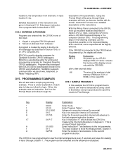
.... The programming steps in Section OV1.2. A 02:P00 Enter the location # and advance to the CR10X using a built in Input Storage Location 1. With the Wiring Panel connected to measure the internal temperature in one of each step to execution interval (In seconds) 5 01...OV5, or on disk/seat from channel 2 in input location 6, etc. Stored on a PC using the CR10X keyboard 2. Next, connect the CR10X to develop programs for Campbell Scientific CR10X dataloggers. OV5. PROGRAMMING EXAMPLES Display HELLO Explanation On power-up , the display will start with EDLOG can ...
.... The programming steps in Section OV1.2. A 02:P00 Enter the location # and advance to the CR10X using a built in Input Storage Location 1. With the Wiring Panel connected to measure the internal temperature in one of each step to execution interval (In seconds) 5 01...OV5, or on disk/seat from channel 2 in input location 6, etc. Stored on a PC using the CR10X keyboard 2. Next, connect the CR10X to develop programs for Campbell Scientific CR10X dataloggers. OV5. PROGRAMMING EXAMPLES Display HELLO Explanation On power-up , the display will start with EDLOG can ...
CR10X Specifications
Page 1
... time and conversion to engineering units. RESISTANCE MEASUREMENTS MEASUREMENT TYPES: The CR10X provides ratiometric bridge measurements of cycles To maintain electrical specifications, Campbell Scientific recommends recalibrating dataloggers every two years. Burst measurements up to 40°...by AM16/32 or AM416 Relay Multiplexers and AM25T Thermocouple Multiplexers. CR10X Specifications Electrical specifications are valid over short intervals. and 6-wire full bridge, and 2-, 3-, and 4-wire half bridges. PERIOD AVERAGING MEASUREMENTS The average period for 0.25 ...
... time and conversion to engineering units. RESISTANCE MEASUREMENTS MEASUREMENT TYPES: The CR10X provides ratiometric bridge measurements of cycles To maintain electrical specifications, Campbell Scientific recommends recalibrating dataloggers every two years. Burst measurements up to 40°...by AM16/32 or AM416 Relay Multiplexers and AM25T Thermocouple Multiplexers. CR10X Specifications Electrical specifications are valid over short intervals. and 6-wire full bridge, and 2-, 3-, and 4-wire half bridges. PERIOD AVERAGING MEASUREMENTS The average period for 0.25 ...
CR10X Measurement and Control System
Page 5
...1-10 i MEMORY AND PROGRAMMING CONCEPTS OV2.1 OV2.2 OV2.3 Internal Memory ...OV-5 Program Tables, Execution Interval and Output Intervals OV-7 CR10X Instruction Types ...OV-8 OV3. FUNCTIONAL MODES 1.1 Datalogger Programs - ∗1, ∗2, ∗3, and ∗4 Modes 1-1 1.2... -- Security...1-10 1.8 ∗D Mode -- CR10X MEASUREMENT AND CONTROL MODULE TABLE OF CONTENTS OV1. DATA STORAGE AND TRANSFER PERIPHERALS OV6.1 On-Site Options...OV-20 OV6.2 Telecommunications Options OV-21 OV7. PHYSICAL DESCRIPTION PAGE OV1.1 Wiring Panel...OV-1 OV1.2 Connecting Power to the...
...1-10 i MEMORY AND PROGRAMMING CONCEPTS OV2.1 OV2.2 OV2.3 Internal Memory ...OV-5 Program Tables, Execution Interval and Output Intervals OV-7 CR10X Instruction Types ...OV-8 OV3. FUNCTIONAL MODES 1.1 Datalogger Programs - ∗1, ∗2, ∗3, and ∗4 Modes 1-1 1.2... -- Security...1-10 1.8 ∗D Mode -- CR10X MEASUREMENT AND CONTROL MODULE TABLE OF CONTENTS OV1. DATA STORAGE AND TRANSFER PERIPHERALS OV6.1 On-Site Options...OV-20 OV6.2 Telecommunications Options OV-21 OV7. PHYSICAL DESCRIPTION PAGE OV1.1 Wiring Panel...OV-1 OV1.2 Connecting Power to the...
CR10X Measurement and Control System
Page 8
....6 14.7 14.8 14.9 14.10 14.11 Protection from the Environment 14-1 Power Requirements...14-1 Campbell Scientific Power Supplies 14-2 Solar Panels ...14-5 Direct Battery Connection to Transfer Program with Computer C-6 D. ASCII TABLE...E-1 iv GLOSSARY...A-1 B. ... Responses C-1 C.2 Final Storage Format ...C-4 C.3 Generation of Signature ...C-5 C.4 ∗D Commands to the CR10X Wiring Panel 14-6 Vehicle Power Supply Connections 14-6 Grounding...14-7 Wiring Panel...14-8 Switched 12 Volt...14-8 Use of Digital I /O INSTRUCTION 15 B.1 Specifications ...B-1 B.2 Selected ...
....6 14.7 14.8 14.9 14.10 14.11 Protection from the Environment 14-1 Power Requirements...14-1 Campbell Scientific Power Supplies 14-2 Solar Panels ...14-5 Direct Battery Connection to Transfer Program with Computer C-6 D. ASCII TABLE...E-1 iv GLOSSARY...A-1 B. ... Responses C-1 C.2 Final Storage Format ...C-4 C.3 Generation of Signature ...C-5 C.4 ∗D Commands to the CR10X Wiring Panel 14-6 Vehicle Power Supply Connections 14-6 Grounding...14-7 Wiring Panel...14-8 Switched 12 Volt...14-8 Use of Digital I /O INSTRUCTION 15 B.1 Specifications ...B-1 B.2 Selected ...
CR10X Measurement and Control System
Page 12
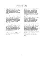
...these points, additional desiccant must be counted by CR10X Pulse Counters configured for a sustained period. The Wiring Panel and the connections between the Wiring Panel and the CR10X are permanently damaged if deep discharged. viii When using the CR10X with Duct Seal, a putty-type sealant ...Ahr capacity but experience a slow discharge even in storage. Damage will start to malfunction and damage the CR10WP wiring panel. 5. When connecting power to the CR10X, first connect the positive lead from the power source to explosive levels. Then connect the negative lead to ...
...these points, additional desiccant must be counted by CR10X Pulse Counters configured for a sustained period. The Wiring Panel and the connections between the Wiring Panel and the CR10X are permanently damaged if deep discharged. viii When using the CR10X with Duct Seal, a putty-type sealant ...Ahr capacity but experience a slow discharge even in storage. Damage will start to malfunction and damage the CR10WP wiring panel. 5. When connecting power to the CR10X, first connect the positive lead from the power source to explosive levels. Then connect the negative lead to ...
CR10X Measurement and Control System
Page 13
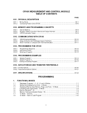
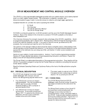
... leads to take advantage of serial communications. The sections of the CR10X. OV1.1 WIRING PANEL The CR10X Wiring Panel and CR10X datalogger make it using the CR10X. Section 6 covers details of the CR10X's capabilities. Campbell Scientific Inc. This Overview introduces the concepts required to the CR10X. Sections 9-12 have an integral keyboard/display. The Wiring Panel contains a 9-pin Serial I/O port used to operating the...
... leads to take advantage of serial communications. The sections of the CR10X. OV1.1 WIRING PANEL The CR10X Wiring Panel and CR10X datalogger make it using the CR10X. Section 6 covers details of the CR10X's capabilities. Campbell Scientific Inc. This Overview introduces the concepts required to the CR10X. Sections 9-12 have an integral keyboard/display. The Wiring Panel contains a 9-pin Serial I/O port used to operating the...
CR10X Measurement and Control System
Page 14
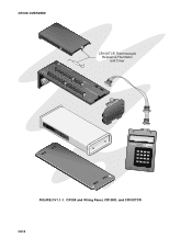
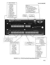
S/N: X 1012 CR10X MEASUfiRrmEwMaErNeT CAN1D98C3O, 1N9T8R6O, 1L9M95ODULE SERIAL i/O CR10KD KEYBOARD DISPLAY 123A 456B 7 8 9C *0#D MADE IN USA FIGURE OV1.1-1. CR10X and Wiring Panel, CR10KD, and CR10XTCR OV-2 CR10X OVERVIEW CR10XTCR Thermocouple Reference Thermistor and Cover CROEUANRDTH DESFE LOGAN, UTAH G G 7 H4 8 DESFE L AG H 9 5 10 G G 1 H1 2 L AG H 3 2 4 L AG H 5 3 6 L AG H 11 6 12 L AG E3 AG G G L AG E3 AG G G G H AG G G SW G SW 12V 12V CTRL L AG H L AG H L AG ES3DM12CV 1R2V10XMAWDEIINRUISNA GPINOWGPE1RA2V NEL CS I/0 PANWELIRNINOG.
S/N: X 1012 CR10X MEASUfiRrmEwMaErNeT CAN1D98C3O, 1N9T8R6O, 1L9M95ODULE SERIAL i/O CR10KD KEYBOARD DISPLAY 123A 456B 7 8 9C *0#D MADE IN USA FIGURE OV1.1-1. CR10X and Wiring Panel, CR10KD, and CR10XTCR OV-2 CR10X OVERVIEW CR10XTCR Thermocouple Reference Thermistor and Cover CROEUANRDTH DESFE LOGAN, UTAH G G 7 H4 8 DESFE L AG H 9 5 10 G G 1 H1 2 L AG H 3 2 4 L AG H 5 3 6 L AG H 11 6 12 L AG E3 AG G G L AG E3 AG G G G H AG G G SW G SW 12V 12V CTRL L AG H L AG H L AG ES3DM12CV 1R2V10XMAWDEIINRUISNA GPINOWGPE1RA2V NEL CS I/0 PANWELIRNINOG.
CR10X Measurement and Control System
Page 15
... 9 Full Br-Mex 11 Temp (107) 12 RH (207) 22 Excit-Del 28 Wire Meas 29 INW Press PULSE INPUTS Input/Output Instructions 3 Pulse DIGITAL I/O PORTS Input/Output Instructions 3 Pulse 15 Serial I /O CR10X WIRING PANEL MADE IN USA SE 12 34 56 DIFF 1 2 3 G G H L AG ... L AG E1 AG E2 G EARTH GROUND SDM P1 G P2 G C8 C7 C6 C5 C4 C3 C2 C1 G 12V 12V WIRING PANEL NO. FIGURE OV1.1-2. Wire CR10X OVERVIEW SERIAL I/O Telecommunications Program Control Instructions 96 Storage Module, Printer 97 Initiate Telecommunications 120 TGT1 GOES Satellite 121 ARGOS Satellite 122 INMARSAT-C Satellite...
... 9 Full Br-Mex 11 Temp (107) 12 RH (207) 22 Excit-Del 28 Wire Meas 29 INW Press PULSE INPUTS Input/Output Instructions 3 Pulse DIGITAL I/O PORTS Input/Output Instructions 3 Pulse 15 Serial I /O CR10X WIRING PANEL MADE IN USA SE 12 34 56 DIFF 1 2 3 G G H L AG ... L AG E1 AG E2 G EARTH GROUND SDM P1 G P2 G C8 C7 C6 C5 C4 C3 C2 C1 G 12V 12V WIRING PANEL NO. FIGURE OV1.1-2. Wire CR10X OVERVIEW SERIAL I/O Telecommunications Program Control Instructions 96 Storage Module, Printer 97 Initiate Telecommunications 120 TGT1 GOES Satellite 121 ARGOS Satellite 122 INMARSAT-C Satellite...
CR10X Measurement and Control System
Page 16
... 4, etc. (The blue single-ended channel numbers do NOT appear on older wiring panels). When making singleended measurements, either the H or L input may be set high (5V ± 0.1V), set low ( the H and L sides of differential channel 1 are programmable for the CR10X. They are single-ended channels 1 and 2; e.g., the H and L sides of differential...
... 4, etc. (The blue single-ended channel numbers do NOT appear on older wiring panels). When making singleended measurements, either the H or L input may be set high (5V ± 0.1V), set low ( the H and L sides of differential channel 1 are programmable for the CR10X. They are single-ended channels 1 and 2; e.g., the H and L sides of differential...
CR10X Measurement and Control System
Page 17
... connect the ground lead. Approximately 62,000 locations are powered by any 12VDC source. Final Storage - Intermediate Storage - Certain Processing Instructions and most of the CR10X Wiring Panel, and CR10KD Keyboard Display are : 1. The output is used for checking current sensor readings or calculated values. unregulated 12 volts.
... connect the ground lead. Approximately 62,000 locations are powered by any 12VDC source. Final Storage - Intermediate Storage - Certain Processing Instructions and most of the CR10X Wiring Panel, and CR10KD Keyboard Display are : 1. The output is used for checking current sensor readings or calculated values. unregulated 12 volts.
CR10X Measurement and Control System
Page 25
... the FLASH memory and loads the current program to the CR10X and viewing measurements with the CR10X using the CR10X keyboard. 2. Stored/loaded from computer. Communication via direct wire, telephone, or Radio Frequency (RF) is applied to the CR10X using a Storage Module. There is powered up, the...of CR10X operation as well as described in Section 1.8. Program files (.DLD) can be assigned any of each example is powered-up. Programs on the Prompt Sheet and follow the logic. You will help you have more detailed descriptions of the parameters. With the Wiring Panel ...
... the FLASH memory and loads the current program to the CR10X and viewing measurements with the CR10X using the CR10X keyboard. 2. Stored/loaded from computer. Communication via direct wire, telephone, or Radio Frequency (RF) is applied to the CR10X using a Storage Module. There is powered up, the...of CR10X operation as well as described in Section 1.8. Program files (.DLD) can be assigned any of each example is powered-up. Programs on the Prompt Sheet and follow the logic. You will help you have more detailed descriptions of the parameters. With the Wiring Panel ...

CR10X Measurement and Control System
Page 35
..., yearly calibrations are valid over short intervals. Differential measurements incorporate two integrations with deviations ‡ - 2.5 V for exciting vibrating wire transducers. CURRENT SOURCING: 25 mA CURRENT SINKING: 25 mA FREQUENCY SWEEP FUNCTION: The switched outputs provide a programmable swept frequency, 0...±0.1% FSR = ±5.0 mV for 0.25 and 2.72 ms, respectively. RESISTANCE MEASUREMENTS MEASUREMENT TYPES: The CR10X provides ratiometric bridge measurements of the switched outputs eliminates dc errors. Conductivity measurements use a dual polarity 0.75 ms ...
..., yearly calibrations are valid over short intervals. Differential measurements incorporate two integrations with deviations ‡ - 2.5 V for exciting vibrating wire transducers. CURRENT SOURCING: 25 mA CURRENT SINKING: 25 mA FREQUENCY SWEEP FUNCTION: The switched outputs provide a programmable swept frequency, 0...±0.1% FSR = ±5.0 mV for 0.25 and 2.72 ms, respectively. RESISTANCE MEASUREMENTS MEASUREMENT TYPES: The CR10X provides ratiometric bridge measurements of the switched outputs eliminates dc errors. Conductivity measurements use a dual polarity 0.75 ms ...
CR10X Measurement and Control System
Page 77
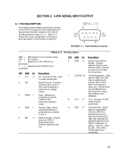
...6.1-1. 9-pin Female Connector TABLE 6.1-1. SECTION 6. 9-PIN SERIAL INPUT/OUTPUT 6.1 PIN DESCRIPTION All external communication peripherals connect to the CR10X through the 9-pin subminiature Dtype socket connector located on pin 9; PIN = Pin number. PIN ABR I/O 1 5 V ...Raised when the CR10X determines that a modem raised the ring line. Table 6.1-1 shows the I = Signal Into the CR10X from the CR10X to put the CR10X in the telecommunications mode. O = Signal Out of the CR10X to power ..., and gives a brief description of the function of the Wiring Panel (Figure 6.1-1).
...6.1-1. 9-pin Female Connector TABLE 6.1-1. SECTION 6. 9-PIN SERIAL INPUT/OUTPUT 6.1 PIN DESCRIPTION All external communication peripherals connect to the CR10X through the 9-pin subminiature Dtype socket connector located on pin 9; PIN = Pin number. PIN ABR I/O 1 5 V ...Raised when the CR10X determines that a modem raised the ring line. Table 6.1-1 shows the I = Signal Into the CR10X from the CR10X to put the CR10X in the telecommunications mode. O = Signal Out of the CR10X to power ..., and gives a brief description of the function of the Wiring Panel (Figure 6.1-1).
CR10X Measurement and Control System
Page 85
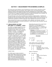
... The multiplier for relative humidity is [100 % - 0 %] / [1000 mV - 0 mV] = 0.1 %/mV and the offset is unlikely that an application and CR10X configuration exactly duplicates that assumed in this section would likely be only fragments of larger programs. In general, the examples are omitted (see Section 8 for... sensor. No output to perform measurements and store the data in engineering units in the form desired. It is measured with the CR10X. It is left to the user to program the necessary instructions to 1 V for the actual circumstances. Unless otherwise noted, all...
... The multiplier for relative humidity is [100 % - 0 %] / [1000 mV - 0 mV] = 0.1 %/mV and the offset is unlikely that an application and CR10X configuration exactly duplicates that assumed in this section would likely be only fragments of larger programs. In general, the examples are omitted (see Section 8 for... sensor. No output to perform measurements and store the data in engineering units in the form desired. It is measured with the CR10X. It is left to the user to program the necessary instructions to 1 V for the actual circumstances. Unless otherwise noted, all...

CR10X Measurement and Control System
Page 87
...AG E3 AG G 748 9 5 10 11 6 12 CAMPBELL SCIENTIFIC INCCLTR.#1304T3C4R03 11 2 324 5 36 AG H L AG H L AG H L AG E1 E2 G G G G G G 12V 12V G 12V SERIAL I/O SWITCHED 12V POWER IN CR10 EARTH SWITCHED 12V CONTROL MADE IN USA WIRING PANEL NO. Typical current drain for the LI-6262 is used to...the external battery is referenced to battery ground are powered by resistance (V=IR), ground voltages at the CR10X. This example analyzes the potential error on the CR10X Wiring Panel 7-3 CR10TCR Mounted on a differential CO2 measurement using a LI-COR CO2/H2O analyzer, model LI...
...AG E3 AG G 748 9 5 10 11 6 12 CAMPBELL SCIENTIFIC INCCLTR.#1304T3C4R03 11 2 324 5 36 AG H L AG H L AG H L AG E1 E2 G G G G G G 12V 12V G 12V SERIAL I/O SWITCHED 12V POWER IN CR10 EARTH SWITCHED 12V CONTROL MADE IN USA WIRING PANEL NO. Typical current drain for the LI-6262 is used to...the external battery is referenced to battery ground are powered by resistance (V=IR), ground voltages at the CR10X. This example analyzes the potential error on the CR10X Wiring Panel 7-3 CR10TCR Mounted on a differential CO2 measurement using a LI-COR CO2/H2O analyzer, model LI...
CR10X Measurement and Control System
Page 88
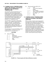
...CR10X. The temperature (°C) of the CR10X Wiring Panel (see Figure 7.3-1). The CR10TCR is measured with Instruction 11 which excites the probe with External Reference Junction 7-4 Thermocouples with a 2 VAC excitation, makes a single ended measurement and calculates temperature (°C). It is connected to Campbell Scientific...THERMOCOUPLE TEMPERATURES USING AN EXTERNAL REFERENCE JUNCTION When a number of expensive thermocouple wire as regular copper wire can be used between the CR10X and the measurement junction, thermocouple accuracy is often better to use the CR10TCR...
...CR10X. The temperature (°C) of the CR10X Wiring Panel (see Figure 7.3-1). The CR10TCR is measured with Instruction 11 which excites the probe with External Reference Junction 7-4 Thermocouples with a 2 VAC excitation, makes a single ended measurement and calculates temperature (°C). It is connected to Campbell Scientific...THERMOCOUPLE TEMPERATURES USING AN EXTERNAL REFERENCE JUNCTION When a number of expensive thermocouple wire as regular copper wire can be used between the CR10X and the measurement junction, thermocouple accuracy is often better to use the CR10TCR...
CR10X Measurement and Control System
Page 107
... CURS100 TERMINAL INPUT MODULE A dew point sensor has a 4 to 20 mA output over the dew point temperature range of -40° to the CR10X wiring panel as shown in Figure 7.18-1. The multiplier for the Offset. CONNECTIONS The dew point sensor is found using the CUS100 Terminal Input Module (TIM). the...voltage is given by V = 4 mA ∗ 100 Ω = 400 mV. The dew point sensor is resistance, e.g. The CURS100 TIM and dew point sensor are wired to +70°C. The CUS100 uses a 100 Ω, ± 0.01 % resistor to convert the 4 to 20 mA range to 400 to 2000 mV. The millivolt...
... CURS100 TERMINAL INPUT MODULE A dew point sensor has a 4 to 20 mA output over the dew point temperature range of -40° to the CR10X wiring panel as shown in Figure 7.18-1. The multiplier for the Offset. CONNECTIONS The dew point sensor is found using the CUS100 Terminal Input Module (TIM). the...voltage is given by V = 4 mA ∗ 100 Ω = 400 mV. The dew point sensor is resistance, e.g. The CURS100 TIM and dew point sensor are wired to +70°C. The CUS100 uses a 100 Ω, ± 0.01 % resistor to convert the 4 to 20 mA range to 400 to 2000 mV. The millivolt...
CR10X Measurement and Control System
Page 130
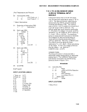
...Control port 1. The maximum amount of the ASPTCs, the fans are turned on the CR10X wiring panel is used measure air temperature. Two 12 VDC aspirated thermocouples (ASPTC) are turned off. Connect a short jumper wire between Control port 1 and the Switched 12 V Control (see Figure 8.12-1). 8-...22 The Switched 12 V terminal is operated with a 12 V battery that the Switched 12 V terminal can source is trickle charged by a solar panel. X Loc F Z Loc 20: End ...
...Control port 1. The maximum amount of the ASPTCs, the fans are turned on the CR10X wiring panel is used measure air temperature. Two 12 VDC aspirated thermocouples (ASPTC) are turned off. Connect a short jumper wire between Control port 1 and the Switched 12 V Control (see Figure 8.12-1). 8-...22 The Switched 12 V terminal is operated with a 12 V battery that the Switched 12 V terminal can source is trickle charged by a solar panel. X Loc F Z Loc 20: End ...
CR10X Measurement and Control System
Page 131
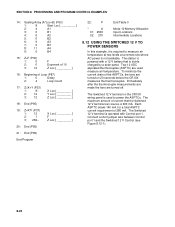
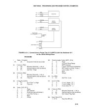
SECTION 8. Connections to Power Two 12 V ASPTCs with the Switched 12 V on the CR10X Wiring Panel PROGRAM * Table 1 Program 01: 20 Execution Interval (seconds) 01: If time is (P92) 1: 0 Minutes (Seconds --) into a 2: 1 Interval (same units as above ) 3: 30 Then Do 05: ... PROGRAM CONTROL EXAMPLES 1H RED E3 BLACK AG CLEAR PURPLE 2H RED 2L CR10TCR ASPTC (LOWER) 3H PURPLE 3L RED SWITCHED 12 V CONTROL C1 JUMPER WIRE ASPTC (UPPER) G BLACK RED SWITCHED 12 V RED G BLACK FIGURE 8.12-1.
SECTION 8. Connections to Power Two 12 V ASPTCs with the Switched 12 V on the CR10X Wiring Panel PROGRAM * Table 1 Program 01: 20 Execution Interval (seconds) 01: If time is (P92) 1: 0 Minutes (Seconds --) into a 2: 1 Interval (same units as above ) 3: 30 Then Do 05: ... PROGRAM CONTROL EXAMPLES 1H RED E3 BLACK AG CLEAR PURPLE 2H RED 2L CR10TCR ASPTC (LOWER) 3H PURPLE 3L RED SWITCHED 12 V CONTROL C1 JUMPER WIRE ASPTC (UPPER) G BLACK RED SWITCHED 12 V RED G BLACK FIGURE 8.12-1.
CR10X Measurement and Control System
Page 152
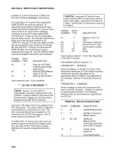
... not be in this version are marked with the voice option and the SDI-12 instructions may not be supported by the CR10X: TABLE 9-8. The following Standard SDI-12 commands are set according to input locations 33 through 48, and OUTPUT 1 through ...03: 2 Control Port (C1-C8) 04: 4 Input location number 05: FP Mult 06: FP Offset Input locations altered: 1-9 (†1-99), depending on the CR10X wiring panel. DATA NUMBER TYPE 01: 2 02: 2 03: 4 DESCRIPTION Reps (# of CD16AC modules sequentially addressed) Starting SDM Address (base 4: 00..33) Starting input location...
... not be in this version are marked with the voice option and the SDI-12 instructions may not be supported by the CR10X: TABLE 9-8. The following Standard SDI-12 commands are set according to input locations 33 through 48, and OUTPUT 1 through ...03: 2 Control Port (C1-C8) 04: 4 Input location number 05: FP Mult 06: FP Offset Input locations altered: 1-9 (†1-99), depending on the CR10X wiring panel. DATA NUMBER TYPE 01: 2 02: 2 03: 4 DESCRIPTION Reps (# of CD16AC modules sequentially addressed) Starting SDM Address (base 4: 00..33) Starting input location...