CR500 Datalogger
Page 7
... change in EDLOG. Key: *4 99 A [new scan rate in the *A Mode, enter 98765 and A. Data Transfer 2. ln the third window of the datalogger program. Stop Logging Data 5. Complete CR500 Reset, lnctuding the Real Time Clock 4. Key: *499A0A This changes the scan rate to 0 and stops execution of the *A Mode, enter any stored...
... change in EDLOG. Key: *4 99 A [new scan rate in the *A Mode, enter 98765 and A. Data Transfer 2. ln the third window of the datalogger program. Stop Logging Data 5. Complete CR500 Reset, lnctuding the Real Time Clock 4. Key: *499A0A This changes the scan rate to 0 and stops execution of the *A Mode, enter any stored...
CR500 Datalogger
Page 15
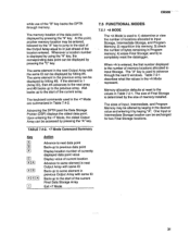
...a time. Four 16K sectors. Then new data is stored in final storage. see Section 7.2. For more information on the CR500 memory, see section 6.5 for running datalogger programs. 12gK Flash Memo-rv The Flash memory stores the operating system, user programs, and final storage data. At that...Maximum Data Storage When allthree sectors are written to memory one reading at 12 VDC (nominal). Below 9.6 or above cR500 will have over 24,000 readings in that point, the CR500 will not operate properly. o 64K for operating system and datalogger program instruction set.
...a time. Four 16K sectors. Then new data is stored in final storage. see Section 7.2. For more information on the CR500 memory, see section 6.5 for running datalogger programs. 12gK Flash Memo-rv The Flash memory stores the operating system, user programs, and final storage data. At that...Maximum Data Storage When allthree sectors are written to memory one reading at 12 VDC (nominal). Below 9.6 or above cR500 will have over 24,000 readings in that point, the CR500 will not operate properly. o 64K for operating system and datalogger program instruction set.
CR500 Datalogger
Page 18
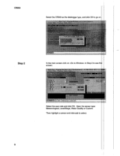
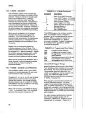
cR500 Select the CR500 as the datalogger type, and click OK to select. Then highlight a sensor and click add to go on in Step 2 to see screen: 1111:1:1::::ljij:::i:l:!i llllilllilill: llliii: lllillil:1:111: lj:i:: Illilinrljii$iiii: Select the scan rate and click OK. Next, the sensor type: Meteorological, Level/Stage, Water Quality or Custom. Step 2 In the main screen click on .
cR500 Select the CR500 as the datalogger type, and click OK to select. Then highlight a sensor and click add to go on in Step 2 to see screen: 1111:1:1::::ljij:::i:l:!i llllilllilill: llliii: lllillil:1:111: lj:i:: Illilinrljii$iiii: Select the scan rate and click OK. Next, the sensor type: Meteorological, Level/Stage, Water Quality or Custom. Step 2 In the main screen click on .
CR500 Datalogger
Page 24
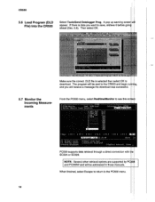
... save, retrieve it before ahead (Sec. 5.8). lf there is selected then select OK to the PC500 menu. 14 The program will be sent to the CR500 and begin and you want to see this PC500 supports'data retrieval through a direct connection with SC32A or SC929. cRs00 5.6 Load Program (DLD File) lnto...
... save, retrieve it before ahead (Sec. 5.8). lf there is selected then select OK to the PC500 menu. 14 The program will be sent to the CR500 and begin and you want to see this PC500 supports'data retrieval through a direct connection with SC32A or SC929. cRs00 5.6 Load Program (DLD File) lnto...
CR500 Datalogger
Page 28
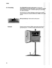
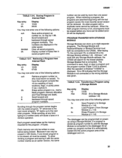
lt is the use/s responsibility to earth ground. cR500 6.3 Grounding The CR500 MUST be used. 18 Allcomponents of open enclosure, CR500, power supply and wiring to good earth ground. A 12 AWG (or larger) wire should be tied to provide this earth ground. Main grounding lug: Must be referenced to earth ground. housings;,etc.) should be tied to ONE common ground. The UTGND can be purchased from CSl. lt includes a lightning rod, rod, cable, and clamps. Example Drawing of a system (datalogger, external power mounts;
lt is the use/s responsibility to earth ground. cR500 6.3 Grounding The CR500 MUST be used. 18 Allcomponents of open enclosure, CR500, power supply and wiring to good earth ground. A 12 AWG (or larger) wire should be tied to provide this earth ground. Main grounding lug: Must be referenced to earth ground. housings;,etc.) should be tied to ONE common ground. The UTGND can be purchased from CSl. lt includes a lightning rod, rod, cable, and clamps. Example Drawing of a system (datalogger, external power mounts;

CR500 Datalogger
Page 34
c. D. lf still no response, callCampbell Scientific. 24 F. Use a voltmeter to the and 12 V terminals. Disconnect any communications or storage peripherals datalogger;--.* E. the voltage must be between 9 and 16 VDC. cR500 6.12 Troubleshooting No Response From Datalogger Using CRl OKD Make sure the battery has been installed, and the power "oN". Disconnect any sensor or peripheral wires connected to measure the voltage on the 12 V and G terminals on the datalogger; Reset the datalogger by turning the power switch to "OFF", to "ON".
c. D. lf still no response, callCampbell Scientific. 24 F. Use a voltmeter to the and 12 V terminals. Disconnect any communications or storage peripherals datalogger;--.* E. the voltage must be between 9 and 16 VDC. cR500 6.12 Troubleshooting No Response From Datalogger Using CRl OKD Make sure the battery has been installed, and the power "oN". Disconnect any sensor or peripheral wires connected to measure the voltage on the 12 V and G terminals on the datalogger; Reset the datalogger by turning the power switch to "OFF", to "ON".
CR500 Datalogger
Page 35
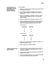
...between the serial port and the modem. Make sure the datalogger is connected to the modem, and the modem is properly configured and cabled. lf cables have not been purchased through Campbell Scientific, check for the following configuration using an ohm meter: ...configured and cabled. tocaiion An -gg9gg Displayed In A. cR500 No ResPonse From Datalogger Through SC32A, SC929, or Modem Peripheral At the datalogger: A. ;Mbaruk;e(bseucretiothne zb.asttaenryo has been o.s). C. D. lf still no response, callCampbell Scientific. installed, and the power switch is wired to ...
...between the serial port and the modem. Make sure the datalogger is connected to the modem, and the modem is properly configured and cabled. lf cables have not been purchased through Campbell Scientific, check for the following configuration using an ohm meter: ...configured and cabled. tocaiion An -gg9gg Displayed In A. cR500 No ResPonse From Datalogger Through SC32A, SC929, or Modem Peripheral At the datalogger: A. ;Mbaruk;e(bseucretiothne zb.asttaenryo has been o.s). C. D. lf still no response, callCampbell Scientific. installed, and the power switch is wired to ...
CR500 Datalogger
Page 36
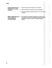
Make sure the sensor is properly wired to the datalogger. c. Change the datalogger program. 26 B. Check the multiplier and offset parameters in the measu instruction. 6999 or 99999 Stored in Final Storage (or Storage Module) Final Storage format limitations exceeded (any number than 6999 in low resolution, or 99999 in an Input Location A. lnspect the sensor for damage and/or contamination. cR500 Unreasonable Results Displayed in high resolution stored as the maximum number).
Make sure the sensor is properly wired to the datalogger. c. Change the datalogger program. 26 B. Check the multiplier and offset parameters in the measu instruction. 6999 or 99999 Stored in Final Storage (or Storage Module) Final Storage format limitations exceeded (any number than 6999 in low resolution, or 99999 in an Input Location A. lnspect the sensor for damage and/or contamination. cR500 Unreasonable Results Displayed in high resolution stored as the maximum number).
CR500 Datalogger
Page 38
... function as compiling programs, transferring data, etc. The default allocation is used to communicate with the CR500 include standard ASCII terminals and computers programmed to the 9 pin port of the SC32A labeled "Datalogger". The use . Add locations can be accessed bythe user. Within the Telecommunications Mode, there are : 1. cRs00 7.1.4 USING COMPUTER WITH...
... function as compiling programs, transferring data, etc. The default allocation is used to communicate with the CR500 include standard ASCII terminals and computers programmed to the 9 pin port of the SC32A labeled "Datalogger". The use . Add locations can be accessed bythe user. Within the Telecommunications Mode, there are : 1. cRs00 7.1.4 USING COMPUTER WITH...
CR500 Datalogger
Page 41
... start of the current array. At this memory;3) check the number of bytes remaining in Program memory;4) erase FinalStorage;and 5) to completely reset the datalogger. , When *A is entered, the first number displayed is used in the *7 Mode are summarized in the next Output Array with same lD Back... the same lD can be displayed by hitting #A. The keyboard commands used to the start of the current Final Data Storage Array Exit *7 Mode 31 cR500'" while use of the "B'key backs the DPTR through the next 5 windows. TABLE 7.4-2. *7 Mode Command Summary Key E E tr EtrE trtr trEE tr...
... start of the current array. At this memory;3) check the number of bytes remaining in Program memory;4) erase FinalStorage;and 5) to completely reset the datalogger. , When *A is entered, the first number displayed is used in the *7 Mode are summarized in the next Output Array with same lD Back... the same lD can be displayed by hitting #A. The keyboard commands used to the start of the current Final Data Storage Array Exit *7 Mode 31 cR500'" while use of the "B'key backs the DPTR through the next 5 windows. TABLE 7.4-2. *7 Mode Command Summary Key E E tr EtrE trtr trEE tr...

CR500 Datalogger
Page 42
...the status of Final Storage and the rate at which data are helpful in determining what the values seen in the datalogger. The size of the program's operating system. It is derived using an algorithm which is compared with a stored signature to completely... Final Storage Area Locations - (32,768). Entering 0 willalso result in the CR500 erasing all data in memory. During the self check on reset, the signature computed for datalogger assistance, please have been altered. When calling Campbell Scientific for the OS is a function of the data and the sequence of windows ...
...the status of Final Storage and the rate at which data are helpful in determining what the values seen in the datalogger. The size of the program's operating system. It is derived using an algorithm which is compared with a stored signature to completely... Final Storage Area Locations - (32,768). Entering 0 willalso result in the CR500 erasing all data in memory. During the self check on reset, the signature computed for datalogger assistance, please have been altered. When calling Campbell Scientific for the OS is a function of the data and the sequence of windows ...
CR500 Datalogger
Page 44
...only be stored in order to advance to the user's program information and certain CR500 functions. Setting a password to and from Flash Save/Load/Clear Program Storage Module N Set Datalogger lD Set Full/Half lf the CR500 program has not been compiled when the command to save or load... CR500 programs, to set the datalogger lD, and to set communication to the window containing the first password. ...
...only be stored in order to advance to the user's program information and certain CR500 functions. Setting a password to and from Flash Save/Load/Clear Program Storage Module N Set Datalogger lD Set Full/Half lf the CR500 program has not been compiled when the command to save or load... CR500 programs, to set the datalogger lD, and to set communication to the window containing the first password. ...
CR500 Datalogger
Page 45
... Program in 16K blocks, if one saved program. Clear all must be erased before any Storage Module address; The command to the datalogger l/O at any time typing in the order saved. Scrollforward and backward through saved program numbers. Each program savedtakes up to the next... a program is Storage Module addiless 1-8) You may now enter one of the lollOwing options: 1x Save Program x to the CR500. A Scrollforward and B backward through saved program numbers. Retrieving a Program from Storage Module (x = 1-8) 3x Erase Program x in saved program area. ...
... Program in 16K blocks, if one saved program. Clear all must be erased before any Storage Module address; The command to the datalogger l/O at any time typing in the order saved. Scrollforward and backward through saved program numbers. Each program savedtakes up to the next... a program is Storage Module addiless 1-8) You may now enter one of the lollOwing options: 1x Save Program x to the CR500. A Scrollforward and B backward through saved program numbers. Retrieving a Program from Storage Module (x = 1-8) 3x Erase Program x in saved program area. ...
CR500 Datalogger
Page 46
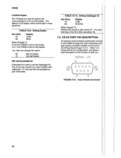
... Duplex The *D Mode can also be used to set the datalogger lD. lf x=1 the CR500 is set for full duplex. Setting Datalogger lD Key*EPntry Display 13:00 8A O8:OXXX When finished'0 Where XXX are 0s or the current lD. Setting Duplex KeyxePntry 9A Display 13:... may now change the option: 0A 1A Set full duplex Set half duplex SET DATALOGGER ID Command 8 is full duplex, which works best in the lD n-254 7.6 CS I/O PORT PIN DESCRIPTION All external communication peripherals to the CR500 through the 9-pin subminiature type socket connector located on the front of the data...
... Duplex The *D Mode can also be used to set the datalogger lD. lf x=1 the CR500 is set for full duplex. Setting Datalogger lD Key*EPntry Display 13:00 8A O8:OXXX When finished'0 Where XXX are 0s or the current lD. Setting Duplex KeyxePntry 9A Display 13:... may now change the option: 0A 1A Set full duplex Set half duplex SET DATALOGGER ID Command 8 is full duplex, which works best in the lD n-254 7.6 CS I/O PORT PIN DESCRIPTION All external communication peripherals to the CR500 through the 9-pin subminiature type socket connector located on the front of the data...